EP0733972B1 - Method and apparatus for managing relationships among objects in a distributed object environment - Google Patents
Method and apparatus for managing relationships among objects in a distributed object environment Download PDFInfo
- Publication number
- EP0733972B1 EP0733972B1 EP96301656A EP96301656A EP0733972B1 EP 0733972 B1 EP0733972 B1 EP 0733972B1 EP 96301656 A EP96301656 A EP 96301656A EP 96301656 A EP96301656 A EP 96301656A EP 0733972 B1 EP0733972 B1 EP 0733972B1
- Authority
- EP
- European Patent Office
- Prior art keywords
- identifier
- objects
- relationship
- role
- computer control
- Prior art date
- Legal status (The legal status is an assumption and is not a legal conclusion. Google has not performed a legal analysis and makes no representation as to the accuracy of the status listed.)
- Expired - Lifetime
Links
Images


Classifications
-
- G—PHYSICS
- G06—COMPUTING; CALCULATING OR COUNTING
- G06F—ELECTRIC DIGITAL DATA PROCESSING
- G06F9/00—Arrangements for program control, e.g. control units
- G06F9/06—Arrangements for program control, e.g. control units using stored programs, i.e. using an internal store of processing equipment to receive or retain programs
- G06F9/46—Multiprogramming arrangements
- G06F9/465—Distributed object oriented systems
-
- G—PHYSICS
- G06—COMPUTING; CALCULATING OR COUNTING
- G06F—ELECTRIC DIGITAL DATA PROCESSING
- G06F9/00—Arrangements for program control, e.g. control units
- G06F9/06—Arrangements for program control, e.g. control units using stored programs, i.e. using an internal store of processing equipment to receive or retain programs
- G06F9/44—Arrangements for executing specific programs
- G06F9/448—Execution paradigms, e.g. implementations of programming paradigms
- G06F9/4488—Object-oriented
- G06F9/4493—Object persistence
Definitions
- the present invention relates to the fields of distributed computing systems, client-server computing and object-oriented programming. More specifically, the present invention includes a method and apparatus for managing objects that are associated through relationship objects in a distributed object environment.
- Object oriented programming strategies tend to avoid these problems because object methodologies focus on manipulating data rather than procedures; thus providing the programmer with a more intuitive approach to modeling real world problems.
- objects encapsulate related data and procedures so as to hide that information from the remainder of the program by allowing access to the data and procedures only through the object's interface.
- changes to the data and or procedures of the object are relatively isolated from the remainder of the program.
- This provides code that is more easily maintained as compared to code written using traditional methods, as changes to an object's code do not affect the code in the other objects.
- the inherent modular nature of objects allows individual objects to be reused in different programs. Thus, programmers can develop libraries of "tried and true" objects that can be used over and over again in different applications. This increases software reliability while decreasing development time; as reliable programming code may be used repeatedly.
- object-servers provide interfaces to object-clients that make requests of the object-servers.
- these servers are objects consisting of data and associated methods.
- the object-clients obtain access to the functionalities of the object-servers by executing calls on them, which calls are mediated by the distributed system.
- the object-server receives the call it executes the appropriate method and transmits the result back to the object-client.
- the object-client and object-server communicate through an Object Request Broker (ORB) which is used to locate the various distributed objects and establish communications therebetween (Rao 1993).
- ORB Object Request Broker
- object metaphor in distributed systems is a useful technique as it separates the object's interface from its implementation; thus allowing software designers to take advantage of the functionalities of various objects available to them without having to worry about the details of the object's implementation.
- the programmer need only be aware of the object's interface.
- object oriented distributed systems allow for multiple implementations of a single interface, which interface may reside on different computing platforms that have been connected through a network.
- a programmer working on one machine of a network may make a call to an object about which the programmer has no detailed knowledge with the confidence that at the appropriate time that the remote object will be accessed and return its data so that the programmers code will function properly.
- Such a system thus maximizes the inherent advantages of object oriented methodologies by taking full advantage of their modularity and encapsulation.
- Object relationships are associations between objects from one or more classes (Rumbaugh 1987).
- the use of relationships allows the object programmer to express clearly the associations and constraints among objects that would otherwise have to be buried in the implementation code of object, thereby reducing the modularity of the object.
- the externalization of references between objects that is provided by the use of relationships permits a symmetric, non-redundant model that combines the object oriented computing model with the entity relationship model that is found in database theory. Such strategies are particularly useful for modeling systems of interrelated objects, as these systems can be thought of in very natural terms.
- the modeling of a document contained in a folder which is a popular metaphor for file storage in many computer systems, can be modeled by relating a folder object with a document object through a "containment" relationship.
- Such a model expresses the relationships in a very natural manner to the real-world case of a folder in which is placed a document for storage.
- relationship methodologies and distributed object oriented systems methods must also exist to ensure that relationships are created among objects in a logically consistent manner.
- the present invention includes methods and apparatus for managing relationships among objects in a distributed object system.
- the limitations imposed on such systems by the need to identify object references which refer to identical objects, provide for the logically consistent formation of relationships among objects and enhance system efficiency by providing for efficient identification of objects associated through relationships are addressed.
- the present invention includes a computer implemented method for determining whether a first object is identical to a second object in a distributed object system including a first object reference residing in a process running in a computer memory, which first object reference refers to the first object, and a second object reference stored in a computer memory that refers to the second object.
- the method includes first providing an identifier for each of the first and second objects that is effective to identify uniquely those objects within the distributed object system.
- the object reference to the second object is then passed to the first object, which initiates a request to the second object for that object's unique identifier.
- the first object determines if its unique identifier is identical to the second object's unique identifier.
- the unique identifier comprises a network address, a process identifier, a temporal value, and an incrementor value.
- the present invention also provides apparatus for determining whether two object references in the distributed object system refer to identical objects.
- the apparatus includes a first object reference associated with the first object and a second object reference associated with the second object; an identity mechanism for providing an identifier for each of the first and second objects which identifier is effective to identify uniquely each of the objects in a distributed object system; a communications medium for passing the second object reference to the first object, and for initiating a request from the first object to the second object for the unique identifier of the second object; and an identity checking mechanism for determining whether the first object's unique identifier is identical to the second object's unique identifier.
- the present invention includes a method and apparatus for managing relationships among distributed objects in a distributed object environment. Using the methods and apparatus of the present invention, distributed objects in a distributed object environment may be handled across diverse platforms, operating systems, and machines in a consistent and efficient manner.
- distributed object refers to an encapsulated package of code and data that can be manipulated by operations defined in the interface distributed object.
- distributed objects will be seen by those skilled in the art as including the basic properties that define traditional programming objects.
- distributed objects differ from traditional programming objects by the inclusion of two important features.
- distributed objects are location-independent, i . e ., distributed objects can be located anywhere in a network. This contrasts sharply with traditional programming objects which typically exist in a single address space: the address space of the client.
- Distributed objects can be object-clients or object-servers, depending upon whether they are sending requests to other objects or replying to requests from other objects. Requests and replies are made through an ORB that is aware of the locations and status of the objects.
- a "distributed object system” or distributed object environment” refers to a system comprising remote objects that communicate through an object request broker (ORB) that is aware of the locations and status of the objects in the distrumped object system.
- ORB object request broker
- a preferred system architecture for implementing such an ORB is provided by the Common Object Request Broker Architecture (CORBA) specification.
- the CORBA specification is defined by the Object Management Group (OMG), a consortium of vendors including Sun Microsystems, Incorporated, Digital Electronics Corporation, Hyperdesk Corporation, Hewlett-Packard Corporation, SunSoft, NCR Corporation and Object Design, Incorporated.
- OMG Object Management Group
- a distributed object system is defined in terms of a client-server model wherein target objects, or servers, provides services to clients that request such services.
- object reference contains a pointer to another object.
- object references will be familiar with those skilled in the art (SunSoft 1994).
- a "client” as defined herein refers to an entity that sends a request to another object, which other object is referred to herein as a "server".
- clients invoke operations, or implementations, from servers.
- clients need not have knowledge of the implementation programming language, nor does the implementation have to have knowledge of the client's programming language due to the requirement of multilingual character of such objects.
- Clients and servers in distributed object environments need only communicate in terms of the interface definition language.
- the request by the client to the server, and the server's reply to the client is handled by the ORB.
- object interface is a specification of the operations, attributes, and exceptions that an object provides.
- object interfaces for distributed objects are written using, e.g., IDL.
- IDL e.g., IDL.
- objects perform transactions through their interfaces. The use of interfaces therefore relieves the need of objects that are aware of the programming languages used to define the methods and data of the objects in the transaction.
- a “relationship” or “relationship object” is an object that forms an association between two or more objects that would otherwise be written in the implementation code of the associated objects (Rumbaugh 1987; Rumbaugh, et al . 1992).
- a folder object i . e ., a directory
- Each object in the relationship has a "role” which is expressed by a "role name”.
- Relationship objects can be operated upon to affect all of the objects associated by the relationship without operating on each object in the relationship individually, thereby allowing for the use of concise expressions to manipulate multiple objects in a natural manner.
- a "relationship service” is a set of facilities available on each machine in a distributed object system for establishing and managing relationships among the distributed objects of the distributed object system.
- the methods described below are implemented in a relationship service in accordance with OMG TC Document 94.5.5.
- the methods and apparatus described below can implemented with relationship services that are designed in accordance with other specifications, or the methods and apparatus of the invention can be used alone or in combination outside of a relationship service.
- network 100 includes computer 102 which computer is coupled to a network 104.
- Network 104 can further include a server, router or the like 106 in addition to other computers 108, 110, and 112 such that data and instructions can be passed among the networked computers.
- the design, construction and implementation of computer networks will be familiar to those of skill in the art.
- Computers 102, 106, 108, 110, and 112 are illustrated schematically with respect to Figure 2 at 200.
- Each computer includes a central processing unit (CPU) 202 which CPU is coupled bidirectionally with random access memory (RAM) 204 and unidirectionally with read only memory (ROM) 206.
- RAM 204 includes programming instructions and data, including distributed objects and their associated data and instructions, for processes currently operating on CPU 202.
- ROM 206 typically includes basic operating instructions, data and objects used by the computer to perform its functions.
- a mass storage device 208 such as a hard disk, CD ROM, magneto-optical (floptical) drive, tape drive or the like, is coupled bidirectionally with CPU 202.
- Mass storage device 208 generally includes additional programming instructions, data and objects that typically are not in active use by the CPU, although the address space may be accessed by the CPU, e.g. , for virtual memory or the like.
- Each of the above described computers further includes an input/output source 210 that typically includes input media such as a keyboard, pointer devices (e.g., a mouse or stylus) and the like.
- Each computer can also include a network connection 212. Additional mass storage devices (not shown) may also be connected to CPU 202 through network connection 212. It will be appreciated by those skilled in the art that the above described hardware and software elements, as well as networking devices, are of standard designing construction are well familiar.
- FIG. 3 Such a scenario is illustrated in Figure 3 at 300 where a first address space 302 contains a process 304 which process includes an object reference A, shown at 306, and an object reference B, shown at 308.
- Object reference A contains the address of a first object O shown at 312 which object is located in address space 310.
- Object reference B includes the address of a second object O', that may be identical to object O, shown at 314 and located in address space 310. It will be appreciated that objects O and O' can be in different address spaces.
- Figure 4 at 400 illustrates a method for distinguishing whether two object references (e.g. , objrefs A and B in Figure 3), respectively, actually refer to the same object through the incorporation of unique identifiers in each object.
- the object referred to by objref A receives objref B.
- the second object which is referenced by objref B, is queried by the first object, referenced by objref A, for the second object's unique identifier (ID B ).
- the first object determines whether its own unique identifier (ID A ) is identical to that of the identifier of the second object. If the two identifiers are equal an affirmative, answer is returned at 410; otherwise, a negative answer is returned at 412. The process ends at step 414.
- the creation of objects having unique identifiers is described in Figure 5 at 500. Beginning with initialization step 502, creation of a unique ID for the object at step 504 precedes the creation of the object itself at step 506. At step 508, the unique ID is stored in a suitable location with respect to the object and the completed object is returned to the user at step 510 after which the procedure ends at step 512. It will be appreciated that the step of creating the unique ID and the step of creating the object may be reversed. In other words, the object may be created before the unique ID is created.
- the object identifier is preferably stored either in the reference data extension of the object or the persistent data storage associated with the object. However, it will be appreciated however that the unique ID may be stored in any location which is accessible to the object.
- the network address for the machine on which the object is being created is obtained at step 604.
- the process ID for the process that is creating the identifiable object is obtained in 606 and the current local system time is obtained at step 608.
- a value from an incrementor associated with the process is obtained at step 610 and the machine address, process ID, local system time and increment value are concatenated to form a single string at step 612, which string is stored in a memory location accessible to the object as described above with respect to step 508.
- Preferred memory locations include those locations for which access can be accomplished efficiently, such as the memory space assigned for persistent storage for the object. The use of persistent data storage will be familiar to those of skill in the art. Execution of sequence 600 terminates at step 614.
- a preferred machine address is the network IP address for the machine and will be familiar to those of skill in the art.
- the process ID is obtained by querying the operating system of the machine in which the object is being created.
- the current system time is obtained typically by a call to the operating system of the system.
- Increment value 610 is obtained by calling a local counter, which counter differentiates various threads that are being executed simultaneously. These procedures will be familiar to those skilled in the art of multithreaded computing.
- Objects that support the IdentifiableObject interface implement an attribute of type ObjectIdentifier and the is_identical operation.
- the ObejctIdentifier is defined for each object in accordance with the procedures described above with respect to Figures 5 and 6.
- the machine address provides a unique identifier across all of the machines on the network, as each machine has a predefined network address.
- the process ID provides uniqueness across processes that are running on the same machine. However, it will be appreciated by those of skill in the art that process IDs on UNIX machines may be not unique over time, and thus present a possible degeneracy. This degeneracy is cured by referring to the local system time for processes which are launched at different times.
- an incrementor provides an identifier for each thread that is independent of time.
- a string carrying all of the above described information will be seen to provide an identifier for an object that is unique with respect to other objects in the distributed object environment.
- the querying object performs the is_identical operation at step 408 of Figure 4.
- the is_identical operation is defined below: This operation returns "true” if the object and the other_object are identical, i . e ., both objects have the same identifier. Otherwise the operation returns "false”.
- the present invention includes a method and apparatus for checking the logical consistency of a relationship to be formed among two or more objects.
- Figures 7A and 7B illustrate relationships between three different objects. As shown at 700 in Figure 7A, a relationship is demonstrated among a document object 702, a graphic object 704, and a folder object 706. Document object 702 and Graphic object 704 are related through relationship object 708. Folder object 706 and document object 702 are related by relationship 710. Each object also has an associated role for each type of relationship in which the object participates. Thus, document object 702 has an associated role 714 with respect to relationship 708 and a second role 718 with respect to relationship 710. Folder object 706 has role 716 with respect to relationship 710 and Graphic object 704 has role 712 with respect to relationship 708. Relationships 708 and 710 typically are referred to as "containment" relationships.
- Roles 712 and 718 as commonly referred to as “contained-in” roles and roles 716 and 714 are often referred to as “contains” roles.
- the use of relationship objects to form associations among objects is well known in the art (Rumbaugh 1987; Rumbaugh 1991; Martin and Cattell 1994).
- relationship objects allows the most generalized use of each of the objects 702, 704 and 706, as each object can be associated through different relationships in different roles without modification of the object.
- a new role is simply associated with object for each new relationship.
- Figure 7B illustrates an alternative association of folder, document and graphic objects at 730 in which Folder object 732 holds Document object 734 and Graphic object 736 through containment relationship objects 738 and 740, respectively.
- Folder object 732 has only one role ⁇ a contains role-while Document object 734 and Graphic object 736 each have contained-in roles.
- relationship objects are created through the use of factory objects, which factory objects accept as arguments the objects to be related and their respective roles, and output the appropriate relationship object.
- the creation of such relationship factories is described with respect to Figure 8 at 800.
- the role types for the objects to be related through the relationship factory object are received by the factory object that creates the relationship factory at step 804.
- the relationship factory object is then created in step 806 and the role types are stored in the relationship factory object as an Expectation Array [E 1 , ..., E N ], where E i is a stored role type for the i th role and N is the degree of the relationship, at step 808 after which process is terminated at step 810.
- step 906 the roles of the objects to be related are received by the relationship factory object at 904.
- a determination is made at step 906 as to whether the proper number of roles for the relationship to be created has been received. If the proper number of roles has not been received, i . e ., an error has occurred, the error is reported at 908 and the sequence terminates at step 910.
- a type check for each role is performed, and, at step 914, a determination is made as to whether the type check meets the expected output.
- the role types for the objects to be related are retrieved from an interface repository that holds descriptions of the interfaces of the objects and their type IDs. Alternatively, the objects could be queried directly by use of a narrow() or an is_a() operation. If the expectation is not met, then, at step 908, an error is returned and the process ends at step 910. If however, the type check does meet the expectation, then, at 916 the relationship object is created. At 918 check is made as to whether a cardinality error was returned during the relationship object creation step and an appropriate error is return at step 908 if the check is true. If there is no cardinality error, then the formed relationship object is returned at 920.
- Type check step 908 is described in greater detail in Figure 10 at 1000.
- a type check array having a dimension equal to the number of role types is initialized, e.g. , all array components are set to 0, at step 1004.
- the expectation array [E 1 , ..., E N ] is retrieved and a first loop is defined whose loop index runs over the number N of roles that are received by the factory object.
- a second loop 1008 runs over the number of retrieved role types whose index is defined by j, wherein j runs from 1 to N.
- the role type may be obtained from an interface repository or directly from the object. If the determination at step 1010 is true, the value contained in the j th element of the type check array is incremented at step 1012, otherwise the loop index j is incremented and the next received role type is examined against the next stored role type. Once all N stored role types have been examined, the loop index i is incremented and the next received role type is checked against all of the stored role types. When all received role types have been checked against all stored role types, i . e ., both loop indices have run from 1 to N, the process terminates at step 1014.
- step 916 of Figure 9 The creation of the relationship object, step 916 of Figure 9, is illustrated in greater detail at 1100 in Figure 11.
- the desired relationship object is created at step 1104 and a loop over the M roles to be linked to the relationship object begins at step 1106.
- the i th role is linked to the relationship object by the operation Role i ⁇ Link(Relationship) at step 1108.
- a determination as to whether the Role i ⁇ Link(Relationship) operation returned a cardinality error is made at step 1110. If no error is returned, the linked relationship is stored at step 1112 and next role is retrieved as the loop increments at step 1104. When all M roles have been linked successfully, the completed relationship object is returned at step 1120.
- step 1110 If, however, a cardinality error is returned at step 1110, the relationship object is destroyed at step 1114 and a cardinality error is returned at step 1116 before the procedure terminates at step 1118. It will be appreciated by those of skill in the art that the foregoing steps of creating relationship objects, linking roles to the objects, and checking the number, type and cardinality constraints can be implemented using known techniques.
- the type check array would be a 1 ⁇ 2 array, with one column representing the number of contains roles received by the relationship factory and the other column representing the number of contained_in roles received. Initially the type check array would be [0,0], signifying that no contains roles or contained_in roles have been identified.
- the expectation array would also be a 1 ⁇ 2 array, but with the value [1,1], signifying that one each of a contains role and a contained_in role is expected.
- the relationship object is created and the roles are linked to the relationship object as described above.
- the cardinality for each of the roles to be linked to the relationship object is checked to ensure that the minimum and maximum cardinality constraints are met.
- the minimum cardinality is the minimum number of relationship instances in which a role must participate.
- the maximum cardinality is the maximum number of relationship instances in which a role may participate. In the present example, each role R 1 and R 2 must participate in at least one relationship.
- the create operation of the CosRelationships module would be invoked to pass the named roles that represent the related objects in the relationship.
- those roles would be the contains and contained_in roles associated with the Folder, Document and/or Graphic objects.
- a determination that the number of roles passed to the relationship factory was too few or too many would generate a DegreeError exception from the relationship factory.
- a determination that the role types passed to the relationship factory are in error would generate a RoleTypeError exception.
- a determination that cardinality is exceeded generates a MaxCardinalityExceeded error. Minimum cardinality can be checked using the check_minimun_cardinality() operation. If the number of roles, the role types and the cardinalities of the roles were in agreement with the relationship, the factory would create the relationship object and inform the roles using a link operation that passes to the role a relationship and a set of roles that represent the objects related in the relationship.
- the present invention includes a method and apparatus for caching object references (objrefs) and roles for the object(s) related to a given object by a relationship in the role of the given object.
- This caching increases the efficiency of navigation through a relationship as the objref and role to each of the other objects in the relationship can be found in the role of any one object. Without such caching, the role would have to send a request to the role for each of the other objects thus increasing the system overhead involved with traversal of a relationship.
- the objref to a relationship object R and the role name RN of a first object that is related to a second object having a second object role by relationship object R are received by the second object role in step 1204.
- the objref is stored in the look up table referred to in step 1206.
- the above described method is implemented in accordance with the Role Interface of the above-described CosRelationships module using the call get_other_related_object() having the form shown below:
- UnknownRoleName is raised if target_name is not in the cache of the role being queried. If the role is unaware of the relationship, UnknownRelationship is raised.
- the objref for a role related in a relationship to a first role can be determined in a similar manner. Referring now to Figure 13 at 1300, beginning with step 1302, a instruction pathway similar to that described with respect to Figure 13 is followed. At step 1304, an objref to a relationship object R and a role name RN are passed to the first role in step 1304. A determination is made as to whether the role that is related by R for the role name RN has already been stored in the look table at step 1306. If the answer is yes, then the objref for the role is returned to step 1308 and termination follows at step 1310. Otherwise, the relationship is queried for the role name RN in step 1312 and the objref for the role is then retrieved and stored in the look up table at step 1314.
- the above described method is implemented in accordance with the Role Interface of the above-described CosRelationships module using the call get_other_role() having the form shown below:
- UnknownRoleName is raised if target_name is not in the cache of the role being queried. If the role is unaware of the relationship, UnknownRelationship is raised.
- the above described method is implemented in accordance with the Role Interface of the above-described CosRelationships module.
- passing the call get_other_role() to the contains role 716 of the Folder object 706, using as arguments an objref to the containment relationship 710 and the role name "contains_in”, would prompt role 716 to look up the objref for document 702 in a look-up table cached with the role object 716. If the objref for contains_in role object 718 was found, the objref would be returned.
- containment relationship 710 would be queried using the named_roles attribute which returns the objrefs for the roles of the relationship. This objref is stored in the look-up table and returned.
- the present invention provides important methods for managing relationships among objects across distributed object systems.
- distributed objects stored at diverse memory location across networks can be identified uniquely, that relationships can be defined consistently between objects and that process operations can be speeded through the use of an automatic caching in which roles for related objects contain object references directed to the objects related to the roles.
Landscapes
- Engineering & Computer Science (AREA)
- Software Systems (AREA)
- Theoretical Computer Science (AREA)
- Physics & Mathematics (AREA)
- General Engineering & Computer Science (AREA)
- General Physics & Mathematics (AREA)
- Information Retrieval, Db Structures And Fs Structures Therefor (AREA)
- Computer And Data Communications (AREA)
- Multi Processors (AREA)
Description
- The present invention relates to the fields of distributed computing systems, client-server computing and object-oriented programming. More specifically, the present invention includes a method and apparatus for managing objects that are associated through relationship objects in a distributed object environment.
- Object oriented programming methodologies have received increasing attention over the past several years in response to the increasing tendency for software developed using traditional programming methods to be delivered late and over budget (Taylor 1990; Gibbs 1994). One problem with traditional programming techniques stems from the emphasis placed on procedural models and "linear" code that often is extremely difficult to design and maintain for many problems. Generally, large programs created using traditional methods are "brittle", that is, even small changes can effect all elements of the programming code. Thus, minor changes made to the software in response to user demands can require major redesign and rewriting of the entire program.
- Object oriented programming strategies tend to avoid these problems because object methodologies focus on manipulating data rather than procedures; thus providing the programmer with a more intuitive approach to modeling real world problems. In addition objects encapsulate related data and procedures so as to hide that information from the remainder of the program by allowing access to the data and procedures only through the object's interface. Hence changes to the data and or procedures of the object are relatively isolated from the remainder of the program. This provides code that is more easily maintained as compared to code written using traditional methods, as changes to an object's code do not affect the code in the other objects. In addition, the inherent modular nature of objects allows individual objects to be reused in different programs. Thus, programmers can develop libraries of "tried and true" objects that can be used over and over again in different applications. This increases software reliability while decreasing development time; as reliable programming code may be used repeatedly.
- However, the full promise of object oriented methodologies, especially the advantages afforded by their modularity, have yet to be achieved. In particular, it would be highly desirable to allow programmers and other users access to objects in a transparent fashion so that objects created in different programming languages and objects residing on different computing platforms that are networked together are accessible to the user without extensive modification of the user's programming code.
- Attempts to provide such facilities have been made using object oriented distributed systems that are based upon a client-server model, in which object-servers provide interfaces to object-clients that make requests of the object-servers. Typically in such systems, these servers are objects consisting of data and associated methods. The object-clients obtain access to the functionalities of the object-servers by executing calls on them, which calls are mediated by the distributed system. When the object-server receives the call it executes the appropriate method and transmits the result back to the object-client. The object-client and object-server communicate through an Object Request Broker (ORB) which is used to locate the various distributed objects and establish communications therebetween (Rao 1993).
- The object metaphor in distributed systems is a useful technique as it separates the object's interface from its implementation; thus allowing software designers to take advantage of the functionalities of various objects available to them without having to worry about the details of the object's implementation. The programmer need only be aware of the object's interface. In addition, object oriented distributed systems allow for multiple implementations of a single interface, which interface may reside on different computing platforms that have been connected through a network. Thus, a programmer working on one machine of a network may make a call to an object about which the programmer has no detailed knowledge with the confidence that at the appropriate time that the remote object will be accessed and return its data so that the programmers code will function properly. Such a system thus maximizes the inherent advantages of object oriented methodologies by taking full advantage of their modularity and encapsulation.
- Efforts to further extend the advantages of object oriented programming techniques have included the development of methodologies to enhance the modularity of programming objects. Once such effort has included development of the concept of relations or relationships between objects. Object relationships are associations between objects from one or more classes (Rumbaugh 1987). The use of relationships allows the object programmer to express clearly the associations and constraints among objects that would otherwise have to be buried in the implementation code of object, thereby reducing the modularity of the object. The externalization of references between objects that is provided by the use of relationships permits a symmetric, non-redundant model that combines the object oriented computing model with the entity relationship model that is found in database theory. Such strategies are particularly useful for modeling systems of interrelated objects, as these systems can be thought of in very natural terms. For example, the modeling of a document contained in a folder, which is a popular metaphor for file storage in many computer systems, can be modeled by relating a folder object with a document object through a "containment" relationship. Such a model expresses the relationships in a very natural manner to the real-world case of a folder in which is placed a document for storage.
- The implementation of these concepts in distributed object oriented systems remains a difficult task. For example, methods are required to determine whether two or more object references are directed to the same object. The need to make such determinations is also relevant to the implementation of relationships among objects. Often it is useful for the programmer or system administrator to "map" the chain of relationships among associated objects.
- Furthermore, with respect to the implementation of relationship methodologies and distributed object oriented systems methods must also exist to ensure that relationships are created among objects in a logically consistent manner. In other words, it is highly desirable to have a method that would prevent, e.g., a situation in which a document was placed in a containment relationship to a folder. Finally, it is also desirable to provide a method for identifying objects in relationships in a highly efficient manner so as to reduce the overhead imposed by the operating system.
- The present invention includes methods and apparatus for managing relationships among objects in a distributed object system. Using the methods and apparatus of the invention the limitations imposed on such systems by the need to identify object references which refer to identical objects, provide for the logically consistent formation of relationships among objects and enhance system efficiency by providing for efficient identification of objects associated through relationships are addressed.
- In one aspect, the present invention includes a computer implemented method for determining whether a first object is identical to a second object in a distributed object system including a first object reference residing in a process running in a computer memory, which first object reference refers to the first object, and a second object reference stored in a computer memory that refers to the second object. The method includes first providing an identifier for each of the first and second objects that is effective to identify uniquely those objects within the distributed object system. The object reference to the second object is then passed to the first object, which initiates a request to the second object for that object's unique identifier. The first object then determines if its unique identifier is identical to the second object's unique identifier. In a preferred embodiment, the unique identifier comprises a network address, a process identifier, a temporal value, and an incrementor value.
- The present invention also provides apparatus for determining whether two object references in the distributed object system refer to identical objects. The apparatus includes a first object reference associated with the first object and a second object reference associated with the second object; an identity mechanism for providing an identifier for each of the first and second objects which identifier is effective to identify uniquely each of the objects in a distributed object system; a communications medium for passing the second object reference to the first object, and for initiating a request from the first object to the second object for the unique identifier of the second object; and an identity checking mechanism for determining whether the first object's unique identifier is identical to the second object's unique identifier.
- These and other aspects and advantages of the present invention will become apparent when the description of specific embodiments below is read in conjunction with the accompanying figures.
-
- Figure 1 is an illustration of various computers linked together in a computer network.
- Figure 2 illustrates diagramatically the major components of a computer in Figure 1.
- Figure 3 is an illustration of two object references associated with a process running on a computer, which object references point to objects located at a remote memory location.
- Figure 4 is a flow diagram of a method for determining whether two object references point to identical objects.
- Figure 5 is a diagrammatic illustration of a process for creating an object having a unique identifier for an object.
- Figure 6 is a detail of
block 504 of Figure 5. - Figures 7A and 7B illustrate relationships among objects. Figure 7A illustrates a relationship in which a folder object contains a document object which document object contains a graphic object. Figure 7B illustrates a relationship in which a folder object contains both a document object and a graphic object.
- Figure 8 illustrates schematically a process for providing stored role types in a factory object for generating relationship objects.
- Figure 9 illustrates a method for determining whether an appropriate number of roles and role types have been passed to a factory object effective for creating a relationship among two or more objects.
- Figure 10 is a diagrammatic illustration of the process described at
step 908 of Figure 9. - Figure 11 illustrates
step 916 of Figure 9. - Figure 12 is a diagrammatic illustration of a process for caching object references to an object in a relationship.
- Figure 13 is a diagrammatic illustration of a method for caching an object reference to a role associated with an object in a relationship.
-
- The present invention includes a method and apparatus for managing relationships among distributed objects in a distributed object environment. Using the methods and apparatus of the present invention, distributed objects in a distributed object environment may be handled across diverse platforms, operating systems, and machines in a consistent and efficient manner.
- As used herein, the term "distributed object" or "object" refers to an encapsulated package of code and data that can be manipulated by operations defined in the interface distributed object. Thus, distributed objects will be seen by those skilled in the art as including the basic properties that define traditional programming objects. However, distributed objects differ from traditional programming objects by the inclusion of two important features. First, distributed objects are multilingual. The interfaces of distributed objects are defined using an interface definition language that can be mapped to a variety of different programming languages. One such interface definition language is IDL. Second, distributed objects are location-independent, i.e., distributed objects can be located anywhere in a network. This contrasts sharply with traditional programming objects which typically exist in a single address space: the address space of the client. Distributed objects can be object-clients or object-servers, depending upon whether they are sending requests to other objects or replying to requests from other objects. Requests and replies are made through an ORB that is aware of the locations and status of the objects.
- A "distributed object system" or distributed object environment" refers to a system comprising remote objects that communicate through an object request broker (ORB) that is aware of the locations and status of the objects in the distrubuted object system. A preferred system architecture for implementing such an ORB is provided by the Common Object Request Broker Architecture (CORBA) specification. The CORBA specification is defined by the Object Management Group (OMG), a consortium of vendors including Sun Microsystems, Incorporated, Digital Electronics Corporation, Hyperdesk Corporation, Hewlett-Packard Corporation, SunSoft, NCR Corporation and Object Design, Incorporated. Under the CORBA, a distributed object system is defined in terms of a client-server model wherein target objects, or servers, provides services to clients that request such services.
- An "object reference" or "objref" contains a pointer to another object. The creation and definition of object references will be familiar with those skilled in the art (SunSoft 1994).
- A "client" as defined herein refers to an entity that sends a request to another object, which other object is referred to herein as a "server". Thus, clients invoke operations, or implementations, from servers. In a distributed object environment, clients need not have knowledge of the implementation programming language, nor does the implementation have to have knowledge of the client's programming language due to the requirement of multilingual character of such objects. Clients and servers in distributed object environments need only communicate in terms of the interface definition language. As noted above, the request by the client to the server, and the server's reply to the client, is handled by the ORB.
- An "object interface," is a specification of the operations, attributes, and exceptions that an object provides. Preferably, object interfaces for distributed objects are written using, e.g., IDL. As noted above, objects perform transactions through their interfaces. The use of interfaces therefore relieves the need of objects that are aware of the programming languages used to define the methods and data of the objects in the transaction.
- A "relationship" or "relationship object" is an object that forms an association between two or more objects that would otherwise be written in the implementation code of the associated objects (Rumbaugh 1987; Rumbaugh, et al. 1992). For example, a folder object (i.e., a directory) can hold a document object through a "containment" relationship. Each object in the relationship has a "role" which is expressed by a "role name". Relationship objects can be operated upon to affect all of the objects associated by the relationship without operating on each object in the relationship individually, thereby allowing for the use of concise expressions to manipulate multiple objects in a natural manner.
- A "relationship service" is a set of facilities available on each machine in a distributed object system for establishing and managing relationships among the distributed objects of the distributed object system. In a preferred embodiment of the present invention, the methods described below are implemented in a relationship service in accordance with OMG TC Document 94.5.5. However, it will be appreciated that the methods and apparatus described below can implemented with relationship services that are designed in accordance with other specifications, or the methods and apparatus of the invention can be used alone or in combination outside of a relationship service.
- In a preferred embodiment of the present invention, distributed objects are located on one or more computers linked together by network such as the network illustrated at 100 in Figure 1. As seen in the Figure,
network 100 includescomputer 102 which computer is coupled to anetwork 104.Network 104 can further include a server, router or the like 106 in addition toother computers -
Computers RAM 204 includes programming instructions and data, including distributed objects and their associated data and instructions, for processes currently operating onCPU 202.ROM 206 typically includes basic operating instructions, data and objects used by the computer to perform its functions. In addition, amass storage device 208, such as a hard disk, CD ROM, magneto-optical (floptical) drive, tape drive or the like, is coupled bidirectionally withCPU 202.Mass storage device 208 generally includes additional programming instructions, data and objects that typically are not in active use by the CPU, although the address space may be accessed by the CPU, e.g., for virtual memory or the like. Each of the above described computers further includes an input/output source 210 that typically includes input media such as a keyboard, pointer devices (e.g., a mouse or stylus) and the like. Each computer can also include anetwork connection 212. Additional mass storage devices (not shown) may also be connected toCPU 202 throughnetwork connection 212. It will be appreciated by those skilled in the art that the above described hardware and software elements, as well as networking devices, are of standard designing construction are well familiar. - As noted above, the use of distributed objects leads to uncertainties as to whether two or more object references are directed to a single object. Such a scenario is illustrated in Figure 3 at 300 where a
first address space 302 contains aprocess 304 which process includes an object reference A, shown at 306, and an object reference B, shown at 308. Object reference A contains the address of a first object O shown at 312 which object is located inaddress space 310. Object reference B includes the address of a second object O', that may be identical to object O, shown at 314 and located inaddress space 310. It will be appreciated that objects O and O' can be in different address spaces. - Figure 4 at 400 illustrates a method for distinguishing whether two object references (e.g., objrefs A and B in Figure 3), respectively, actually refer to the same object through the incorporation of unique identifiers in each object. Beginning with
initialization step 402, the object referred to by objref A receives objref B. Atstep 406, the second object, which is referenced by objref B, is queried by the first object, referenced by objref A, for the second object's unique identifier (IDB). Atstep 408, the first object then determines whether its own unique identifier (IDA) is identical to that of the identifier of the second object. If the two identifiers are equal an affirmative, answer is returned at 410; otherwise, a negative answer is returned at 412. The process ends atstep 414. - The creation of objects having unique identifiers is described in Figure 5 at 500. Beginning with
initialization step 502, creation of a unique ID for the object atstep 504 precedes the creation of the object itself atstep 506. Atstep 508, the unique ID is stored in a suitable location with respect to the object and the completed object is returned to the user atstep 510 after which the procedure ends atstep 512. It will be appreciated that the step of creating the unique ID and the step of creating the object may be reversed. In other words, the object may be created before the unique ID is created. The object identifier is preferably stored either in the reference data extension of the object or the persistent data storage associated with the object. However, it will be appreciated however that the unique ID may be stored in any location which is accessible to the object. - The formation of the unique ID is described in Figure 6 with respect to
sequence 600. There, followinginitialization step 602, the network address for the machine on which the object is being created is obtained atstep 604. Next, the process ID for the process that is creating the identifiable object is obtained in 606 and the current local system time is obtained atstep 608. In addition, a value from an incrementor associated with the process is obtained atstep 610 and the machine address, process ID, local system time and increment value are concatenated to form a single string atstep 612, which string is stored in a memory location accessible to the object as described above with respect to step 508. Preferred memory locations include those locations for which access can be accomplished efficiently, such as the memory space assigned for persistent storage for the object. The use of persistent data storage will be familiar to those of skill in the art. Execution ofsequence 600 terminates atstep 614. - A preferred machine address is the network IP address for the machine and will be familiar to those of skill in the art. The process ID is obtained by querying the operating system of the machine in which the object is being created. The current system time is obtained typically by a call to the operating system of the system.
Increment value 610 is obtained by calling a local counter, which counter differentiates various threads that are being executed simultaneously. These procedures will be familiar to those skilled in the art of multithreaded computing. - In a preferred embodiment, the above-described procedure is implemented in accordance with the specifications described in OMG TC Document 94.5.5, entitled "Relationship Service Specification". A preferred Relationship Service supports a CosObjectIdentity module which is defined as follows:

- Objects that support the IdentifiableObject interface implement an attribute of type ObjectIdentifier and the is_identical operation. The ObejctIdentifier is defined for each object in accordance with the procedures described above with respect to Figures 5 and 6. The machine address provides a unique identifier across all of the machines on the network, as each machine has a predefined network address. The process ID provides uniqueness across processes that are running on the same machine. However, it will be appreciated by those of skill in the art that process IDs on UNIX machines may be not unique over time, and thus present a possible degeneracy. This degeneracy is cured by referring to the local system time for processes which are launched at different times. However, for cases in which two or more strings are launched on the same process at approximately the same time, i.e., in which the launch times differ by an amount smaller than the granularity of the system clock, an incrementor provides an identifier for each thread that is independent of time. Thus, a string carrying all of the above described information will be seen to provide an identifier for an object that is unique with respect to other objects in the distributed object environment.
- To compare the identifier of the other object with its own identifier, in a preferred embodiment the querying object performs the is_identical operation at
step 408 of Figure 4. The is_identical operation is defined below:This operation returns "true" if the object and the other_object are identical, i.e., both objects have the same identifier. Otherwise the operation returns "false".
- In another aspect, the present invention includes a method and apparatus for checking the logical consistency of a relationship to be formed among two or more objects.
- Figures 7A and 7B illustrate relationships between three different objects. As shown at 700 in Figure 7A, a relationship is demonstrated among a
document object 702, agraphic object 704, and afolder object 706.Document object 702 and Graphic object 704 are related throughrelationship object 708.Folder object 706 anddocument object 702 are related byrelationship 710. Each object also has an associated role for each type of relationship in which the object participates. Thus,document object 702 has an associatedrole 714 with respect torelationship 708 and asecond role 718 with respect torelationship 710.Folder object 706 hasrole 716 with respect torelationship 710 and Graphic object 704 hasrole 712 with respect torelationship 708.Relationships Roles roles - It will be appreciated that the use of relationship objects allows the most generalized use of each of the
objects Folder object 732 holdsDocument object 734 and Graphic object 736 through containment relationship objects 738 and 740, respectively. In this example,Folder object 732 has only one role―a contains role-whileDocument object 734 and Graphic object 736 each have contained-in roles. - However, the formation of some relationships must be prevented in order to preserve logical consistency. For example, a software system might want to prevent a relationship in which a folder is contained in a document. In addition, it is necessary to ensure that each relationship formed includes the requisite number of roles. For example, a containment relationship could not be formed having only a contains role. Finally, the cardinality of the relationship, i.e., the number of relationship instances connected to a role, must also be consistent, as it would also be a breach of logical consistency to allow, e.g., a relationship in which two or more un-nested folders contained a single document. Thus, only relationships which are consistent with respect to the number, types and cardinality can be formed.
- As is well known to those skilled in the art, relationship objects are created through the use of factory objects, which factory objects accept as arguments the objects to be related and their respective roles, and output the appropriate relationship object. The creation of such relationship factories is described with respect to Figure 8 at 800. Starting at
initialization step 802, the role types for the objects to be related through the relationship factory object are received by the factory object that creates the relationship factory atstep 804. The relationship factory object is then created instep 806 and the role types are stored in the relationship factory object as an Expectation Array [E1, ..., EN], where Ei is a stored role type for the ith role and N is the degree of the relationship, atstep 808 after which process is terminated atstep 810. - Turning now to Figure 9 at 900, the method of checking the logical consistency of a relationship to be formed will be described. Beginning with
initialization step 902, the roles of the objects to be related are received by the relationship factory object at 904. A determination is made atstep 906 as to whether the proper number of roles for the relationship to be created has been received. If the proper number of roles has not been received, i.e., an error has occurred, the error is reported at 908 and the sequence terminates atstep 910. - If the proper number of roles is received at 906, however, then, at
step 912, a type check for each role is performed, and, atstep 914, a determination is made as to whether the type check meets the expected output. In a preferred embodiment, the role types for the objects to be related are retrieved from an interface repository that holds descriptions of the interfaces of the objects and their type IDs. Alternatively, the objects could be queried directly by use of a narrow() or an is_a() operation. If the expectation is not met, then, atstep 908, an error is returned and the process ends atstep 910. If however, the type check does meet the expectation, then, at 916 the relationship object is created. At 918 check is made as to whether a cardinality error was returned during the relationship object creation step and an appropriate error is return atstep 908 if the check is true. If there is no cardinality error, then the formed relationship object is returned at 920. -
Type check step 908 is described in greater detail in Figure 10 at 1000. Starting atinitialization step 1002, a type check array having a dimension equal to the number of role types is initialized, e.g., all array components are set to 0, atstep 1004. Atstep 1006, the expectation array [E1, ..., EN] is retrieved and a first loop is defined whose loop index runs over the number N of roles that are received by the factory object. Asecond loop 1008 runs over the number of retrieved role types whose index is defined by j, wherein j runs from 1 to N. Withinsubloop 1008, a determination is made atstep 1010 as to whether the role type received (Ri) is identical to the retrieved role type (Ej) by calling the function Ri→is_a(Ej). As noted above, the role type may be obtained from an interface repository or directly from the object. If the determination atstep 1010 is true, the value contained in the jth element of the type check array is incremented atstep 1012, otherwise the loop index j is incremented and the next received role type is examined against the next stored role type. Once all N stored role types have been examined, the loop index i is incremented and the next received role type is checked against all of the stored role types. When all received role types have been checked against all stored role types, i.e., both loop indices have run from 1 to N, the process terminates atstep 1014. - The creation of the relationship object, step 916 of Figure 9, is illustrated in greater detail at 1100 in Figure 11. Starting at 1102, the desired relationship object is created at
step 1104 and a loop over the M roles to be linked to the relationship object begins atstep 1106. Withinloop 1106, the ith role is linked to the relationship object by the operation Rolei→Link(Relationship) atstep 1108. A determination as to whether the Rolei→Link(Relationship) operation returned a cardinality error is made atstep 1110. If no error is returned, the linked relationship is stored atstep 1112 and next role is retrieved as the loop increments atstep 1104. When all M roles have been linked successfully, the completed relationship object is returned atstep 1120. - If, however, a cardinality error is returned at
step 1110, the relationship object is destroyed atstep 1114 and a cardinality error is returned atstep 1116 before the procedure terminates atstep 1118. It will be appreciated by those of skill in the art that the foregoing steps of creating relationship objects, linking roles to the objects, and checking the number, type and cardinality constraints can be implemented using known techniques. - Thus, for example, in the relationship described in Figure 7A above, the sequence of expected role types stored in the relationship factory for either of the
containment relationships - Continuing with the example, if the first role (R,) received by the relationship factory was a contains role, then, on the first pass through the double loop (i = j = 1), the call R1→is_a(E1) would return a value of 1 or "true", since both R, and E1 are contains roles. The first element of the type check array would then be incremented to yield [1,0]. On the second pass (i = 1, j = 2), however, the call R1→is_a(E2) would return 0, or "false", and the type check array would not change.
- Similarly, on the second pass through loop index i, i = 2, as the second role received (R2) is a contained_in role, the call R2→is_a(E1) would return 0, or "false", and the type check array would not change. On the final pass, however, the call R2→is_a(E2) would return a value of 1 or "true", since both R2 and E2 are contained_in roles. The second element of the type check array would thus be incremented to yield the final result: [1,1]. Referring back to step 910 of Figure 9, the comparison of the type check array against the expectation array would yield a "true" value and the relationship object would be formed.
- If however, R1 and R2 were both contains roles, then the type check array would have a final value of [2,0] since true results would be returned only when j = 1. Under this condition, the comparison of the expectation and type check arrays would yield false and an error would be returned. Similarly, if R1 or R2 was neither contains nor contained_in, an error also would be returned.
- Once the checks for type and number are completed successfully, the relationship object is created and the roles are linked to the relationship object as described above. At this point, the cardinality for each of the roles to be linked to the relationship object is checked to ensure that the minimum and maximum cardinality constraints are met. As used herein, the minimum cardinality is the minimum number of relationship instances in which a role must participate. The maximum cardinality is the maximum number of relationship instances in which a role may participate. In the present example, each role R1 and R2 must participate in at least one relationship.
- In a preferred embodiment, the steps outlined in the above-described example would be implemented using a RelationshipFactory interface of the CosRelationships module in accordance with OMG TC Document 94.5.5. This interface defines a create operation which takes as arguments a sequence of named roles that represent the related objects in the relationship to be created, as shown below:

- The create operation of the CosRelationships module would be invoked to pass the named roles that represent the related objects in the relationship. In the present example, those roles would be the contains and contained_in roles associated with the Folder, Document and/or Graphic objects. A determination that the number of roles passed to the relationship factory was too few or too many would generate a DegreeError exception from the relationship factory. A determination that the role types passed to the relationship factory are in error would generate a RoleTypeError exception. A determination that cardinality is exceeded generates a MaxCardinalityExceeded error. Minimum cardinality can be checked using the check_minimun_cardinality() operation. If the number of roles, the role types and the cardinalities of the roles were in agreement with the relationship, the factory would create the relationship object and inform the roles using a link operation that passes to the role a relationship and a set of roles that represent the objects related in the relationship.
- In another aspect, the present invention includes a method and apparatus for caching object references (objrefs) and roles for the object(s) related to a given object by a relationship in the role of the given object. This caching increases the efficiency of navigation through a relationship as the objref and role to each of the other objects in the relationship can be found in the role of any one object. Without such caching, the role would have to send a request to the role for each of the other objects thus increasing the system overhead involved with traversal of a relationship.
- With respect to Figure 12 at 1200, starting at
initialization step 1202, the objref to a relationship object R and the role name RN of a first object that is related to a second object having a second object role by relationship object R are received by the second object role instep 1204. Atstep 1206, a determination is made as to whether an objref to the first object can be found in a look up table ("LUT") or cache associated with the second role. If the answer is true, then the objref is returned for the first object atstep 1208 and program function terminates atstep 1210. Otherwise, the relationship is queried for the role name RN atstep 1212 and the role RN is then queried for the objref of the first object instep 1214. The objref is stored in the look up table referred to instep 1206. - In a preferred embodiment, the above described method is implemented in accordance with the Role Interface of the above-described CosRelationships module using the call get_other_related_object() having the form shown below:

- This operation navigates the relationship rel to the related object represented by the role named target_name to the related object. The exception UnknownRoleName is raised if target_name is not in the cache of the role being queried. If the role is unaware of the relationship, UnknownRelationship is raised.
- Using the folder-document relationship described in Figure 7A as an example, passing the call get_other_related_object() to contains
role 716 of theFolder object 706, using as arguments an objref tocontainment relationship 710 and the role name "contains_in", would promptrole 716 to look up the objref fordocument 702 in a look-up table associated with therole object 716. If the objref fordocument object 702 was found, the objref would be returned. If the objref was not recorded,containment relationship 710 would be queried using the named_roles attribute which returns the roles of the relationship. The role is then queried using the related_object attribute to determine the objref of the related object. This objref is stored in the look-up table and returned. - The objref for a role related in a relationship to a first role can be determined in a similar manner. Referring now to Figure 13 at 1300, beginning with
step 1302, a instruction pathway similar to that described with respect to Figure 13 is followed. Atstep 1304, an objref to a relationship object R and a role name RN are passed to the first role instep 1304. A determination is made as to whether the role that is related by R for the role name RN has already been stored in the look table atstep 1306. If the answer is yes, then the objref for the role is returned to step 1308 and termination follows atstep 1310. Otherwise, the relationship is queried for the role name RN instep 1312 and the objref for the role is then retrieved and stored in the look up table atstep 1314. - In a preferred embodiment, the above described method is implemented in accordance with the Role Interface of the above-described CosRelationships module using the call get_other_role() having the form shown below:
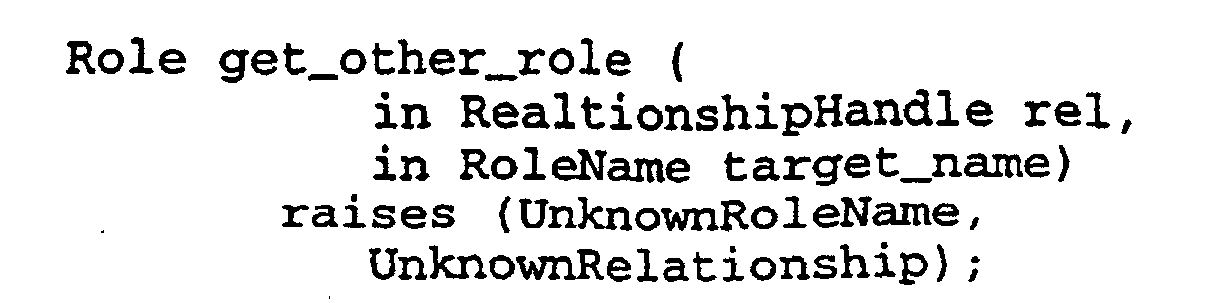
- This operation navigates the relationship rel to the related object represented by the role named target_name to the role. The exception UnknownRoleName is raised if target_name is not in the cache of the role being queried. If the role is unaware of the relationship, UnknownRelationship is raised.
- In a preferred embodiment, the above described method is implemented in accordance with the Role Interface of the above-described CosRelationships module. Using the folder-document relationship described in Figure 7A as an example, passing the call get_other_role() to the contains
role 716 of theFolder object 706, using as arguments an objref to thecontainment relationship 710 and the role name "contains_in", would promptrole 716 to look up the objref fordocument 702 in a look-up table cached with therole object 716. If the objref forcontains_in role object 718 was found, the objref would be returned. If the objref was not recorded,containment relationship 710 would be queried using the named_roles attribute which returns the objrefs for the roles of the relationship. This objref is stored in the look-up table and returned. - Thus, it will be appreciated that the present invention provides important methods for managing relationships among objects across distributed object systems. Using the methods of the present invention, those of skilled in the art will appreciate that distributed objects stored at diverse memory location across networks can be identified uniquely, that relationships can be defined consistently between objects and that process operations can be speeded through the use of an automatic caching in which roles for related objects contain object references directed to the objects related to the roles.
- Interface User's Guide and Reference: Project DOE External Developer's Release 2. 1994. SunSoft.
- Joint Object Services Submission: Relationship Service Specification. 1994. OMG TC Document 94.5.5.
- Gibbs, W. W. 1994. Trends in Computing: Software's Chronic Crisis. Scientific American 271(3): 86-95.
- Martin, B. E., and Cattell, R. G. G. 1994. Relating Distributed Objects. In Proceedings of the 20th VLDB Conference, Santiago, Chile, 1994.
- Taylor, D. 1990. Object Oriented Technology: A Manager's Guide. Addison Wesley.
- Rao, B. R. 1993. C++ and the OOP Paradigm. McGraw-Hill.
- Rumbaugh, J. 1987. Relations as Semantic Constructs in an Object-Oriented Language. In OOPSLA '87 Conference Proceedings. ACM Press.
- Rumbaugh, J., et al.. 1991. Object-Oriented Modeling and Design. Prentice Hall.
Claims (11)
- A computer implemented method in a distributed object system including a plurality of computers interconnected in a computer network in which a first object reference is stored in a memory of a computer, which first object reference refers to a first object residing in a computer controlled process running in a computer memory, and a second object reference is stored in a computer memory, which second object reference refers to a second object residing in a computer controlled process running in a computer memory, said computer implemented method for determining whether said first object is identical to said second object, the method comprising the steps of:a) providing under computer control an identifier for each of said first and said second objects, said identifier being effective to identify uniquely said first object and said second object in said distributed object system;b) passing under computer control said second object reference to said first object;c) initiating under computer control a request from said first object to said second object for said second object's unique identifier using said second object reference; andd) determining under computer control whether said first object's unique identifier is identical to said second objects unique identifier.
- The method of claim 1, wherein said identifier comprises determining under computer control the values of:a) a network address device,b) a process identifier device,c) a temporal value device, andd) an incrementor value device;
- The method of claim 2, wherein said network address device is an IP address of a computer on said network.
- The method of claim 3, wherein for each object said step of providing an identifier comprises the steps of:a) determining under computer control said IP address for the computer in which said object is created;b) determining under computer control the value of said process identifier device of the process creating said object;c) determining under computer control the local current system time;d) determining under computer control the current value of said incrementor value device; ande) concatenating under computer control said IP address, said process identifier device value, said local current system time and said current value to form thereby said identifier.
- The method of claim 4, further including the step of storing under computer control said identifier in a memory space associated with said object, said memory space being contained in a computer on said network.
- The method of claim 5, wherein said identifier is stored in a persistent data structure cached with said object.
- An apparatus for determining whether two object references residing in processes running on one or more computers interconnected in a network in a distributed object system refer to the same object, comprising:a) a first object reference mechanism associated with a first object, and a second object reference mechanism associated with a second object;b) an identifier mechanism for each of said first and said second objects, said identifier mechanism being effective to identify uniquely said first object and said object in said distributed object system;c) a communications medium through which is passed under computer control said second object reference to said first object and through which communications medium a request is sent from said first object to said second object for said second object's unique identifier using said second object reference; andd) an identity checking mechanism to determine under computer control whether said first object's unique identifier is identical to said second object's unique identifier.
- The apparatus of claim 7, wherein said identifier mechanism comprisesa) a network address device,b) a process identifier device,c) a temporal value device, andd) an incrementor value device;
- The apparatus of claim 8, wherein said network address device is an IP address.
- The apparatus of claim 8, wherein said identifier mechanism is located in a memory space associated with said object.
- The apparatus of claim 10, wherein said identifier mechanism is located in a persistent data structure cached with said object.
Applications Claiming Priority (2)
| Application Number | Priority Date | Filing Date | Title |
|---|---|---|---|
| US40863495A | 1995-03-22 | 1995-03-22 | |
| US408634 | 1995-03-22 |
Publications (3)
| Publication Number | Publication Date |
|---|---|
| EP0733972A2 EP0733972A2 (en) | 1996-09-25 |
| EP0733972A3 EP0733972A3 (en) | 1997-06-11 |
| EP0733972B1 true EP0733972B1 (en) | 2003-07-09 |
Family
ID=23617083
Family Applications (1)
| Application Number | Title | Priority Date | Filing Date |
|---|---|---|---|
| EP96301656A Expired - Lifetime EP0733972B1 (en) | 1995-03-22 | 1996-03-11 | Method and apparatus for managing relationships among objects in a distributed object environment |
Country Status (5)
| Country | Link |
|---|---|
| US (2) | US5815710A (en) |
| EP (1) | EP0733972B1 (en) |
| JP (1) | JPH0934823A (en) |
| CA (1) | CA2172221A1 (en) |
| DE (1) | DE69628965T2 (en) |
Families Citing this family (64)
| Publication number | Priority date | Publication date | Assignee | Title |
|---|---|---|---|---|
| DE69628965T2 (en) * | 1995-03-22 | 2004-02-26 | Sun Microsystems, Inc., Mountain View | Method and device for managing relationships between objects in a distributed object environment |
| EP0825506B1 (en) | 1996-08-20 | 2013-03-06 | Invensys Systems, Inc. | Methods and apparatus for remote process control |
| US6647393B1 (en) | 1996-11-22 | 2003-11-11 | Mangosoft Corporation | Dynamic directory service |
| US6026474A (en) * | 1996-11-22 | 2000-02-15 | Mangosoft Corporation | Shared client-side web caching using globally addressable memory |
| US7058696B1 (en) | 1996-11-22 | 2006-06-06 | Mangosoft Corporation | Internet-based shared file service with native PC client access and semantics |
| US6035342A (en) * | 1997-03-19 | 2000-03-07 | Microsoft Corporation | Method and computer program product for implementing object relationships |
| JPH10320367A (en) * | 1997-05-19 | 1998-12-04 | Fujitsu Ltd | Method for communication between objects movable on network and system therefor |
| US5884317A (en) * | 1997-08-20 | 1999-03-16 | Bea Systems, Inc. | Service interface repository |
| US6108664A (en) | 1997-10-31 | 2000-08-22 | Oracle Corporation | Object views for relational data |
| US6182064B1 (en) * | 1998-03-06 | 2001-01-30 | International Business Machines Corporation | Method and system for identifying an object located among a number of multiple interconnected computing systems |
| US6344922B1 (en) * | 1998-07-21 | 2002-02-05 | Corvis Corporation | Optical signal varying devices |
| US7039673B1 (en) * | 1998-12-24 | 2006-05-02 | Computer Associates Think, Inc. | Method and apparatus for dynamic command extensibility in an intelligent agent |
| GB2346983B (en) * | 1999-02-18 | 2003-04-16 | Ibm | Client/server computing for transaction processing with superior coordinator o ptimization |
| US6384933B1 (en) | 1999-03-31 | 2002-05-07 | Marconi Data Systems Inc. | Job control in a printing system utilizing object-oriented modules in a distributed object system |
| AU5025600A (en) | 1999-05-17 | 2000-12-05 | Foxboro Company, The | Process control configuration system with parameterized objects |
| US7089530B1 (en) * | 1999-05-17 | 2006-08-08 | Invensys Systems, Inc. | Process control configuration system with connection validation and configuration |
| US6587261B1 (en) | 1999-05-24 | 2003-07-01 | Corvis Corporation | Optical transmission systems including optical amplifiers and methods of use therein |
| US6788980B1 (en) | 1999-06-11 | 2004-09-07 | Invensys Systems, Inc. | Methods and apparatus for control using control devices that provide a virtual machine environment and that communicate via an IP network |
| US6539425B1 (en) | 1999-07-07 | 2003-03-25 | Avaya Technology Corp. | Policy-enabled communications networks |
| US6529948B1 (en) | 1999-08-31 | 2003-03-04 | Accenture Llp | Multi-object fetch component |
| FR2800218B1 (en) * | 1999-10-22 | 2002-01-11 | Algety Telecom | FIBER OPTIC TRANSMISSION SYSTEM USING RZ PULSES |
| FR2800219B1 (en) * | 1999-10-22 | 2006-06-30 | Algety Telecom | POWER ADJUSTMENT METHOD FOR WAVELENGTH MULTIPLEXING OPTICAL TRANSMISSION SYSTEM |
| US6542907B1 (en) | 2000-03-31 | 2003-04-01 | International Business Machines Corporation | Method and apparatus for decentralized, invertible generation of bounded-length globally unique replica identifiers |
| US6609155B1 (en) * | 2000-05-25 | 2003-08-19 | International Business Machines Corporation | Method and apparatus for providing relationships in simple network management protocol management information base |
| US6795826B2 (en) * | 2000-05-25 | 2004-09-21 | Manyworlds Consulting, Inc. | Fuzzy content network management and access |
| US7689560B2 (en) | 2000-10-13 | 2010-03-30 | Miosoft Corporation | Persistent data storage techniques |
| US7587428B2 (en) * | 2000-10-13 | 2009-09-08 | Microsoft Corporation | Maintaining a relationship between two different items of data |
| US7814198B2 (en) | 2007-10-26 | 2010-10-12 | Microsoft Corporation | Model-driven, repository-based application monitoring system |
| FI20015010A (en) * | 2001-06-08 | 2002-12-09 | Sonera Oyj | Distributed Object Component Network |
| US7107430B2 (en) * | 2001-06-19 | 2006-09-12 | Massachusetts Institute Of Technology | Mechanism to reduce the cost of forwarding pointer aliasing |
| EP1271309A1 (en) * | 2001-06-27 | 2003-01-02 | Interactive Objects Software GmbH | Method and system for managing relations between software components |
| US7533141B2 (en) * | 2003-01-24 | 2009-05-12 | Sun Microsystems, Inc. | System and method for unique naming of resources in networked environments |
| US7246361B1 (en) * | 2003-03-20 | 2007-07-17 | Intuit, Inc. | Supporting multiple late binding objects with the same identifier |
| US7526459B2 (en) | 2003-11-28 | 2009-04-28 | Manyworlds, Inc. | Adaptive social and process network systems |
| US20090018918A1 (en) | 2004-11-04 | 2009-01-15 | Manyworlds Inc. | Influence-based Social Network Advertising |
| US8566263B2 (en) * | 2003-11-28 | 2013-10-22 | World Assets Consulting Ag, Llc | Adaptive computer-based personalities |
| US7606772B2 (en) | 2003-11-28 | 2009-10-20 | Manyworlds, Inc. | Adaptive social computing methods |
| US7526458B2 (en) | 2003-11-28 | 2009-04-28 | Manyworlds, Inc. | Adaptive recommendations systems |
| US7539652B2 (en) | 2003-11-28 | 2009-05-26 | Manyworlds, Inc. | Adaptive self-modifying and recombinant systems |
| USRE45770E1 (en) | 2003-11-28 | 2015-10-20 | World Assets Consulting Ag, Llc | Adaptive recommendation explanations |
| US8600920B2 (en) | 2003-11-28 | 2013-12-03 | World Assets Consulting Ag, Llc | Affinity propagation in adaptive network-based systems |
| US20060015528A1 (en) * | 2004-07-14 | 2006-01-19 | Microsoft Corporation | Generic representation of optional values |
| CN100486193C (en) * | 2004-09-29 | 2009-05-06 | 腾讯科技(深圳)有限公司 | Multi-policy P2P connection establishment method |
| US7975036B2 (en) * | 2006-05-11 | 2011-07-05 | The Mitre Corporation | Adaptive cross-layer cross-node optimization |
| US7801856B2 (en) * | 2006-08-09 | 2010-09-21 | Oracle International Corporation | Using XML for flexible replication of complex types |
| US8024396B2 (en) * | 2007-04-26 | 2011-09-20 | Microsoft Corporation | Distributed behavior controlled execution of modeled applications |
| US7970892B2 (en) * | 2007-06-29 | 2011-06-28 | Microsoft Corporation | Tuning and optimizing distributed systems with declarative models |
| US8239505B2 (en) * | 2007-06-29 | 2012-08-07 | Microsoft Corporation | Progressively implementing declarative models in distributed systems |
| US8230386B2 (en) | 2007-08-23 | 2012-07-24 | Microsoft Corporation | Monitoring distributed applications |
| US8099720B2 (en) | 2007-10-26 | 2012-01-17 | Microsoft Corporation | Translating declarative models |
| US7974939B2 (en) * | 2007-10-26 | 2011-07-05 | Microsoft Corporation | Processing model-based commands for distributed applications |
| US8225308B2 (en) * | 2007-10-26 | 2012-07-17 | Microsoft Corporation | Managing software lifecycle |
| US7926070B2 (en) | 2007-10-26 | 2011-04-12 | Microsoft Corporation | Performing requested commands for model-based applications |
| US8181151B2 (en) * | 2007-10-26 | 2012-05-15 | Microsoft Corporation | Modeling and managing heterogeneous applications |
| CN104407518B (en) | 2008-06-20 | 2017-05-31 | 因文西斯系统公司 | The system and method interacted to the reality and Simulation Facility for process control |
| US8463964B2 (en) | 2009-05-29 | 2013-06-11 | Invensys Systems, Inc. | Methods and apparatus for control configuration with enhanced change-tracking |
| US8127060B2 (en) | 2009-05-29 | 2012-02-28 | Invensys Systems, Inc | Methods and apparatus for control configuration with control objects that are fieldbus protocol-aware |
| US20130166597A1 (en) * | 2011-12-22 | 2013-06-27 | Sap Ag | Context Object Linking Structured and Unstructured Data |
| US10671245B2 (en) | 2017-03-29 | 2020-06-02 | Microsoft Technology Licensing, Llc | Collection and control of user activity set data and activity set user interface |
| US10732796B2 (en) | 2017-03-29 | 2020-08-04 | Microsoft Technology Licensing, Llc | Control of displayed activity information using navigational mnemonics |
| US10693748B2 (en) | 2017-04-12 | 2020-06-23 | Microsoft Technology Licensing, Llc | Activity feed service |
| US10853220B2 (en) | 2017-04-12 | 2020-12-01 | Microsoft Technology Licensing, Llc | Determining user engagement with software applications |
| US11580088B2 (en) | 2017-08-11 | 2023-02-14 | Microsoft Technology Licensing, Llc | Creation, management, and transfer of interaction representation sets |
| EP3623955A1 (en) * | 2018-09-13 | 2020-03-18 | Siemens Aktiengesellschaft | Method for generating identifiers for information units in a distributed system |
Family Cites Families (10)
| Publication number | Priority date | Publication date | Assignee | Title |
|---|---|---|---|---|
| US4905162A (en) * | 1987-03-30 | 1990-02-27 | Digital Equipment Corporation | Evaluation system for determining analogy and symmetric comparison among objects in model-based computation systems |
| US5117351A (en) * | 1988-10-21 | 1992-05-26 | Digital Equipment Corporation | Object identifier generator for distributed computer system |
| US5129083A (en) * | 1989-06-29 | 1992-07-07 | Digital Equipment Corporation | Conditional object creating system having different object pointers for accessing a set of data structure objects |
| US5057996A (en) * | 1989-06-29 | 1991-10-15 | Digital Equipment Corporation | Waitable object creation system and method in an object based computer operating system |
| US5619638A (en) * | 1989-07-31 | 1997-04-08 | Hewlett-Packard Company | Object based computer system having representation objects for providing interpretative views onto a data object |
| JPH09502547A (en) * | 1992-11-13 | 1997-03-11 | マイクロソフト コーポレイション | Method and system for marshalling interface pointers for remote procedure calls |
| US5509123A (en) * | 1994-03-22 | 1996-04-16 | Cabletron Systems, Inc. | Distributed autonomous object architectures for network layer routing |
| US5522077A (en) * | 1994-05-19 | 1996-05-28 | Ontos, Inc. | Object oriented network system for allocating ranges of globally unique object identifiers from a server process to client processes which release unused identifiers |
| EP0684553B1 (en) * | 1994-05-26 | 2004-06-16 | Sun Microsystems, Inc. | Method and apparatus for generating and using short operation identifiers in object oriented systems |
| DE69628965T2 (en) * | 1995-03-22 | 2004-02-26 | Sun Microsystems, Inc., Mountain View | Method and device for managing relationships between objects in a distributed object environment |
-
1996
- 1996-03-11 DE DE69628965T patent/DE69628965T2/en not_active Expired - Fee Related
- 1996-03-11 EP EP96301656A patent/EP0733972B1/en not_active Expired - Lifetime
- 1996-03-20 CA CA002172221A patent/CA2172221A1/en not_active Abandoned
- 1996-03-21 JP JP8065035A patent/JPH0934823A/en active Pending
- 1996-09-17 US US08/718,062 patent/US5815710A/en not_active Expired - Lifetime
-
1997
- 1997-07-10 US US08/891,181 patent/US6697877B1/en not_active Expired - Fee Related
Also Published As
| Publication number | Publication date |
|---|---|
| EP0733972A2 (en) | 1996-09-25 |
| US5815710A (en) | 1998-09-29 |
| DE69628965T2 (en) | 2004-02-26 |
| EP0733972A3 (en) | 1997-06-11 |
| JPH0934823A (en) | 1997-02-07 |
| DE69628965D1 (en) | 2003-08-14 |
| US6697877B1 (en) | 2004-02-24 |
| CA2172221A1 (en) | 1996-09-23 |
Similar Documents
| Publication | Publication Date | Title |
|---|---|---|
| EP0733972B1 (en) | Method and apparatus for managing relationships among objects in a distributed object environment | |
| US5793965A (en) | Method and apparatus for determining the type of an object in a distributed object system | |
| US5327559A (en) | Remote and batch processing in an object oriented programming system | |
| US6976261B2 (en) | Method and apparatus for fast, local CORBA object references | |
| US6704803B2 (en) | Method and system for distributing data events over an information bus | |
| US5758351A (en) | System and method for the creation and use of surrogate information system objects | |
| US6493719B1 (en) | Method and system for scripting for system management information | |
| US5692183A (en) | Methods and apparatus for providing transparent persistence in a distributed object operating environment | |
| US6349342B1 (en) | Methods and apparatus for managing computer processes | |
| US5963947A (en) | Technique of dynamically adding functionality from a client to manipulated data at a server | |
| US5475817A (en) | Object oriented distributed computing system processing request to other object model with code mapping by object managers located by manager of object managers | |
| US8056091B2 (en) | Systems and methods for using application services | |
| US6704804B1 (en) | Method and system for communicating information among interactive applications | |
| US6353860B1 (en) | Methods and apparatus for managing collections of objects | |
| US20020073092A1 (en) | Methods, systems and computer program products for controlling variables associated with transactions in a multiple transaction environment | |
| US6892202B2 (en) | Optimistic transaction compiler | |
| JPH08339355A (en) | Method and apparatus for access to processing task executionin distributed system | |
| CA2360645C (en) | Dynamic generic framework for distributed tooling | |
| US6405363B1 (en) | Class casting support for run-time extensible items in an object oriented framework | |
| US6769125B2 (en) | Methods and apparatus for managing computer processes | |
| US20030061398A1 (en) | Method and system for retrieving data over an information bus | |
| US7958145B2 (en) | Creating multiple MBeans from a factory MBean | |
| Viroli et al. | On Observation as a coordination paradigm: an ontology and a formal framework | |
| Ciftci | Design and implementatin of web based supply centers material request and tracking (SMART) system using with Java and Java servlets | |
| Bouguettaya et al. | Middleware |
Legal Events
| Date | Code | Title | Description |
|---|---|---|---|
| PUAI | Public reference made under article 153(3) epc to a published international application that has entered the european phase |
Free format text: ORIGINAL CODE: 0009012 |
|
| AK | Designated contracting states |
Kind code of ref document: A2 Designated state(s): DE FR GB IT SE |
|
| PUAL | Search report despatched |
Free format text: ORIGINAL CODE: 0009013 |
|
| AK | Designated contracting states |
Kind code of ref document: A3 Designated state(s): DE FR GB IT SE |
|
| 17P | Request for examination filed |
Effective date: 19971203 |
|
| GRAH | Despatch of communication of intention to grant a patent |
Free format text: ORIGINAL CODE: EPIDOS IGRA |
|
| GRAH | Despatch of communication of intention to grant a patent |
Free format text: ORIGINAL CODE: EPIDOS IGRA |
|
| GRAA | (expected) grant |
Free format text: ORIGINAL CODE: 0009210 |
|
| AK | Designated contracting states |
Designated state(s): DE FR GB IT SE |
|
| PG25 | Lapsed in a contracting state [announced via postgrant information from national office to epo] |
Ref country code: IT Free format text: LAPSE BECAUSE OF FAILURE TO SUBMIT A TRANSLATION OF THE DESCRIPTION OR TO PAY THE FEE WITHIN THE PRESCRIBED TIME-LIMIT;WARNING: LAPSES OF ITALIAN PATENTS WITH EFFECTIVE DATE BEFORE 2007 MAY HAVE OCCURRED AT ANY TIME BEFORE 2007. THE CORRECT EFFECTIVE DATE MAY BE DIFFERENT FROM THE ONE RECORDED. Effective date: 20030709 |
|
| REG | Reference to a national code |
Ref country code: GB Ref legal event code: FG4D |
|
| REF | Corresponds to: |
Ref document number: 69628965 Country of ref document: DE Date of ref document: 20030814 Kind code of ref document: P |
|
| PG25 | Lapsed in a contracting state [announced via postgrant information from national office to epo] |
Ref country code: SE Free format text: LAPSE BECAUSE OF FAILURE TO SUBMIT A TRANSLATION OF THE DESCRIPTION OR TO PAY THE FEE WITHIN THE PRESCRIBED TIME-LIMIT Effective date: 20031009 |
|
| PGFP | Annual fee paid to national office [announced via postgrant information from national office to epo] |
Ref country code: FR Payment date: 20040309 Year of fee payment: 9 |
|
| ET | Fr: translation filed | ||
| PLBE | No opposition filed within time limit |
Free format text: ORIGINAL CODE: 0009261 |
|
| STAA | Information on the status of an ep patent application or granted ep patent |
Free format text: STATUS: NO OPPOSITION FILED WITHIN TIME LIMIT |
|
| 26N | No opposition filed |
Effective date: 20040414 |
|
| PGFP | Annual fee paid to national office [announced via postgrant information from national office to epo] |
Ref country code: DE Payment date: 20050304 Year of fee payment: 10 |
|
| PG25 | Lapsed in a contracting state [announced via postgrant information from national office to epo] |
Ref country code: FR Free format text: LAPSE BECAUSE OF NON-PAYMENT OF DUE FEES Effective date: 20051130 |
|
| REG | Reference to a national code |
Ref country code: FR Ref legal event code: ST Effective date: 20051130 |
|
| PGFP | Annual fee paid to national office [announced via postgrant information from national office to epo] |
Ref country code: GB Payment date: 20060308 Year of fee payment: 11 |
|
| PG25 | Lapsed in a contracting state [announced via postgrant information from national office to epo] |
Ref country code: DE Free format text: LAPSE BECAUSE OF NON-PAYMENT OF DUE FEES Effective date: 20061003 |
|
| GBPC | Gb: european patent ceased through non-payment of renewal fee |
Effective date: 20070311 |
|
| PG25 | Lapsed in a contracting state [announced via postgrant information from national office to epo] |
Ref country code: GB Free format text: LAPSE BECAUSE OF NON-PAYMENT OF DUE FEES Effective date: 20070311 |