EP0733870B1 - Dryer housing for floatingly drying a travelling web and method of floatingly guiding a travelling web - Google Patents
Dryer housing for floatingly drying a travelling web and method of floatingly guiding a travelling web Download PDFInfo
- Publication number
- EP0733870B1 EP0733870B1 EP96301832A EP96301832A EP0733870B1 EP 0733870 B1 EP0733870 B1 EP 0733870B1 EP 96301832 A EP96301832 A EP 96301832A EP 96301832 A EP96301832 A EP 96301832A EP 0733870 B1 EP0733870 B1 EP 0733870B1
- Authority
- EP
- European Patent Office
- Prior art keywords
- air
- ducts
- web
- pair
- floatingly
- Prior art date
- Legal status (The legal status is an assumption and is not a legal conclusion. Google has not performed a legal analysis and makes no representation as to the accuracy of the status listed.)
- Expired - Lifetime
Links
- 238000001035 drying Methods 0.000 title claims description 12
- 238000000034 method Methods 0.000 title claims description 7
- 238000004891 communication Methods 0.000 claims description 20
- 230000001105 regulatory effect Effects 0.000 claims description 6
- 230000001276 controlling effect Effects 0.000 claims description 4
- 230000003287 optical effect Effects 0.000 claims description 2
- 238000005188 flotation Methods 0.000 description 6
- OKTJSMMVPCPJKN-UHFFFAOYSA-N Carbon Chemical compound [C] OKTJSMMVPCPJKN-UHFFFAOYSA-N 0.000 description 1
- 101150034459 Parpbp gene Proteins 0.000 description 1
- 238000013459 approach Methods 0.000 description 1
- 229910052799 carbon Inorganic materials 0.000 description 1
- 238000013016 damping Methods 0.000 description 1
- 238000010981 drying operation Methods 0.000 description 1
- 238000003466 welding Methods 0.000 description 1
Images



Classifications
-
- F—MECHANICAL ENGINEERING; LIGHTING; HEATING; WEAPONS; BLASTING
- F26—DRYING
- F26B—DRYING SOLID MATERIALS OR OBJECTS BY REMOVING LIQUID THEREFROM
- F26B13/00—Machines and apparatus for drying fabrics, fibres, yarns, or other materials in long lengths, with progressive movement
- F26B13/10—Arrangements for feeding, heating or supporting materials; Controlling movement, tension or position of materials
- F26B13/101—Supporting materials without tension, e.g. on or between foraminous belts
- F26B13/104—Supporting materials without tension, e.g. on or between foraminous belts supported by fluid jets only; Fluid blowing arrangements for flotation dryers, e.g. coanda nozzles
Definitions
- the present invention relates to a dryer housing for floatingly drying a travelling web and a method of floatingly guiding a travelling web.
- Conventional air bars and air duct delivery systems are designed to obtain even air flow to the web occurs notwithstanding minor disturbances in duct delivery systems. Uneven air distribution is generally considered to be undesirable, since the same can result in drying streaks on the web, improper clearance of the web from the air bar surface, and/or improper flotation of the web (e.g., web flutter).
- a conventional air bar having more than one air receiving port in communication with a duct delivery system if one port is supplied air at a pressure different from that at which another port is supplied air, the air bar is designed so that the two different air supplies mix in an internal chamber of the air bar, allowing even pressure air delivery to the web.
- US 5,199,623 discloses a web flotation dryer on which the pre-characterising portion of claims 1 and 5 is based.
- US 5,105,562 discloses a web dryer having upper finger ducts feeding air bars. Damping means are separately provided in each upper finger duct rather than in the crossover duct connecting the finger ducts.
- a damper is positioned in the header system feeding first and second ducts, which ducts in turn feed each air bar. Proper adjustment of the damper regulates the pressure of supply air in each duct, and compensates for web shift or minimizes or prevents web shift from occurring.
- the present invention provides a dryer housing for floatingly drying a travelling web, said housing comprising:
- the present invention provides a method of floatingly guiding a travelling web, comprising:
- FIG. 1 and 2 there is shown generally at 10 an upper header assembly 11 and a lower header assembly 12, each adapted to receive and be in air flow communication with a plurality of air bars via a pair of finger ducts 30, 31 for floatingly drying a running web.
- the air bar is of the Coanda type such as the Hi-Float air bar commercially available from W.R. Grace & Co.-Conn.
- Each air bar has a pair of air receiving ports adapted to be sealingly connected to the header assembly 11 or 12 via ports 19a, 19b, 19c, etc. in each of the finger ducts 30, 31.
- Each air bar extends over and is fed by two finger ducts, and thus each air bar includes two ports, each corresponding to a port in each of the two finger ducts.
- Each upper and lower header assembly includes two finger ducts 30, 31 which directly feed the air bars as described above.
- the finger ducts 30 are proximal to the gear side A of the dryer, and the finger ducts 31 are proximal to the operator side B of the dryer.
- Located behind each pair of finger ducts 30 and 31 is a crossover duct 33.
- the crossover duct 33 is in communication with a supply fan (not shown) which provides pressurized air to the crossover duct, which in turn provides pressurized air to the finger ducts 30, 31 and ultimately to the plurality of air bars.
- damper actuator 13 Located on the operator side B of the dryer and accessible to the operator is damper actuator 13 having a moveable lever 14.
- the lever 14 is coupled to a first rigid round rod 15 which extends into the dryer enclosure. Movement of the lever 14 causes rotational movement of the first round rod 15.
- the first round rod 15 is coupled via miter gears 17a, 17b to a second round rod 16 positioned perpendicularly to the first round rod 15, as best seen in Figure 4.
- the aforementioned rotational motion of the first round rod 15 causes a similar movement of the second round rod 16 via the miter gears 17a, 17b.
- a damper vane 18 which is preferably a low carbon tabulated sheet.
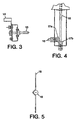
- a V-shaped groove is formed along the length of the damper vane 18, as shown in Figure 5, to accommodate the round bar 16 and to which it is secured such as by welding. Rotational movement of round bar 16 causes rotational movement of damper vane 18 secured to it.
- a damper vane 18 is positioned in each crossover duct 33 which is in air supplying communication with finger ducts 30 and 31. When the damper vane 18 is in the fully open or horizontal position, the supply of air to the crossover duct 33 and subsequently to finger ducts 30 and 31 is substantially unaffected by the damper vane 18.
- the damper vane 18 in the event of web shift, movement of the damper vane 18 towards vertical will cause a pressure differential between finger duct 30 and finger duct 31, which compensates for the web shift. Accordingly, the amount of air supplied to each finger duct 30 and 31 can be regulated based upon the occurrence of web shift, either observed manually or sensed automatically.
- the lower header assembly 12 also has a damper vane 18' controllable in the same way.
- both of the upper and lower header assembly include a damper assembly, and that they can be individually controlled or can be controlled with a single actuator.
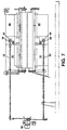
- Figure 7 explicitly shows the embodiment wherein both the upper and lower header assembly are equipped with a damper assembly.
- upper header assembly includes damper vane 18 coupled to a rigid round rod 16, which in turn is coupled to rigid round rod 15 as in the embodiment of Figure 2.
- lower header assembly includes a damper vane 18' coupled to a rigid round rod 16', which in turn is coupled to rigid round rod 15'.
- Each rod 15, 15' is coupled to an actuator 50 as shown.
- the damper assembly can be driven automatically using conventional actuator motors, which respond either to manual input or to an electrical signal generated as a result of web shift.
- a conventional web guide optical sensor such as an infrared sensor
- the infrared sensor can send a signal to the actuator motor or motors, which causes movement of the dampers, preferably in steps, until the shift is less than the set point value, such as less than 30%.
- the upper and lower dampers can be moved as a result of the same signal, or can be moved independently by receiving separate signals.
- the dampers can be manually controlled.
- the operator would watch the web guide indicator and manually control a switch that activates the actuator.
- the switch would be released when the web guide indicator indicates that correction of web shift is no longer necessary.
Landscapes
- Engineering & Computer Science (AREA)
- Textile Engineering (AREA)
- Mechanical Engineering (AREA)
- General Engineering & Computer Science (AREA)
- Drying Of Solid Materials (AREA)
- Treatment Of Fiber Materials (AREA)
- Registering, Tensioning, Guiding Webs, And Rollers Therefor (AREA)
- Advancing Webs (AREA)
Description
- The present invention relates to a dryer housing for floatingly drying a travelling web and a method of floatingly guiding a travelling web.
- Conventional air bars and air duct delivery systems are designed to obtain even air flow to the web occurs notwithstanding minor disturbances in duct delivery systems. Uneven air distribution is generally considered to be undesirable, since the same can result in drying streaks on the web, improper clearance of the web from the air bar surface, and/or improper flotation of the web (e.g., web flutter). Thus, in a conventional air bar having more than one air receiving port in communication with a duct delivery system, if one port is supplied air at a pressure different from that at which another port is supplied air, the air bar is designed so that the two different air supplies mix in an internal chamber of the air bar, allowing even pressure air delivery to the web.
- In addition, as a floating web approaches the edge of an air bar, the pressure pad which allows web flotation collapses, causing web flutter. This phenomenon is similar to the edge of an unattached sail on a sail boat, and in flotation drying, is undesirable. Accordingly, webs are typically positioned about 2,5-10,2 cm (1-4 inches) from the air bar edges.
- It would, however, be desirable to continuously control or compensate for web shift occuring during the drying operation, regardless of the cause thereof. It is therefore an object of the present invention to compensate for such web shift.
- It is a further object of the present invention to provide apparatus to control the pressure differential between two ducts feeding a given air bar.
- US 5,199,623 discloses a web flotation dryer on which the pre-characterising portion of
claims 1 and 5 is based. - US 5,105,562 discloses a web dryer having upper finger ducts feeding air bars. Damping means are separately provided in each upper finger duct rather than in the crossover duct connecting the finger ducts.
- The problems of the prior art have been overcome by the instant invention, which provides for pressure control of air supply feeding air bars and subsequently impinging upon a web, so as to avoid or compensate for web shift without disturbing the cushion pressure and flotation techniques necessary for adequate web flotation and drying. More specifically, a damper is positioned in the header system feeding first and second ducts, which ducts in turn feed each air bar. Proper adjustment of the damper regulates the pressure of supply air in each duct, and compensates for web shift or minimizes or prevents web shift from occurring.
- Accordingly the present invention provides a dryer housing for floatingly drying a travelling web, said housing comprising:
- an upper header assembly comprising a pair of upper ducts arranged to feed air to a plurality of upper air bars for floatingly drying a travelling web;
- said plurality of upper air bars each being in air-receiving communication with said pair of upper ducts;
- an upper crossover duct in air-receiving communication with a supply fan and in air-supplying communication with said pair of upper ducts;
- upper damper means for controlling the pressure differential between said pair of upper ducts whereby web shift can be compensated; characterised in that said upper ducts are finger ducts and in that said upper damper means are in said upper crossover duct; said dryer housing further comprising:
- a lower header assembly comprising a pair of lower finger ducts arranged to feed air to a plurality of lower air bars for floatingly drying a travelling web;
- a plurality of lower air bars each in air-receiving communication with said pair of lower finger ducts;
- a lower crossover duct in air-receiving communication with said supply fan and in air-supplying communication with said pair of lower finger ducts; and
- lower damper means in said lower crossover duct for controlling the said pair of lower pressure differential between finger ducts whereby web shift can be compensated.
-
- Further the present invention provides a method of floatingly guiding a travelling web, comprising:
- providing a supply of air to an upper header assembly including an upper crossover duct;
- feeding said air from said upper crossover duct to a pair of upper ducts in air-supplying communication with a plurality of air bars;
- floating said web on a cushion pressure of air created by said plurality of air bars; and
- regulating the amount of pressurized air fed to said upper ducts in response to shifting of said floating web so as to create a pressure differential between said pair of upper ducts; characterised by:
- providing a supply of air to a lower header assembly including a lower crossover duct;
- feeding said air from said lower crossover duct to a pair of lower finger ducts in air-supplying communication with a plurality of air bars;
- floating said web on a cushion pressure of air created by said plurality of air bars; and
- regulating the amount of pressurised air fed to said lower finger ducts in response to shifting of said floating web so as to create a pressure differential between said pari of lower finger ducts;
- whereby said pair of upper ducts are finger ducts and in that said pressure differentials are created using damper means in said upper and lower crossover ducts.
-
-
- Figure 1 is a side cross-sectional view of a header assembly having an adjustable damper in accordance with the present invention;
- Figure 2 is a front cross-sectional view of the header system of Figure 1 in accordance with the present invention;
- Figure 3 is a cross-sectional view of a portion of the damper actuating assembly taken along line F-F of Figure 2;
- Figure 4 is a cross-sectional view of another portion of the damper actuating assembly taken along line E-E of Figure 2;
- Figure 5 is a cross-sectional view of the damper vane shown coupled to the damper actuating assembly in accordance with the present invention;
- Figure 6 is a bottom cross-sectional view of the upper header assembly of Figure 1 in accordance with the present invention; and
- Figure 7 is a front cross-sectional view of the header system of Figure 1 in accordance with another embodiment of the present invention.
-
- Turning now to Figures 1 and 2, there is shown generally at 10 an
upper header assembly 11 and alower header assembly 12, each adapted to receive and be in air flow communication with a plurality of air bars via a pair offinger ducts header assembly ports finger ducts - Each upper and lower header assembly includes two
finger ducts finger ducts 30 are proximal to the gear side A of the dryer, and thefinger ducts 31 are proximal to the operator side B of the dryer. Located behind each pair offinger ducts crossover duct 33. Thecrossover duct 33 is in communication with a supply fan (not shown) which provides pressurized air to the crossover duct, which in turn provides pressurized air to thefinger ducts - Located on the operator side B of the dryer and accessible to the operator is
damper actuator 13 having amoveable lever 14. As best seen in Figures 3 and 6, thelever 14 is coupled to a firstrigid round rod 15 which extends into the dryer enclosure. Movement of thelever 14 causes rotational movement of thefirst round rod 15. At its distal end, thefirst round rod 15 is coupled viamiter gears second round rod 16 positioned perpendicularly to thefirst round rod 15, as best seen in Figure 4. The aforementioned rotational motion of thefirst round rod 15 causes a similar movement of thesecond round rod 16 via themiter gears - Coupled to
second round bar 16 is adamper vane 18, which is preferably a low carbon tabulated sheet. A V-shaped groove is formed along the length of thedamper vane 18, as shown in Figure 5, to accommodate theround bar 16 and to which it is secured such as by welding. Rotational movement ofround bar 16 causes rotational movement ofdamper vane 18 secured to it. Adamper vane 18 is positioned in eachcrossover duct 33 which is in air supplying communication withfinger ducts damper vane 18 is in the fully open or horizontal position, the supply of air to thecrossover duct 33 and subsequently tofinger ducts damper vane 18. However, in the event of web shift, movement of thedamper vane 18 towards vertical will cause a pressure differential betweenfinger duct 30 andfinger duct 31, which compensates for the web shift. Accordingly, the amount of air supplied to eachfinger duct lower header assembly 12 also has a damper vane 18' controllable in the same way. - It should be understood by those skilled in the art that the respective relative positions of the first and
second round rods assembly including lever 14 should be readily accessible to the operator. Both of the upper and lower header assembly include a damper assembly, and that they can be individually controlled or can be controlled with a single actuator. For example, Figure 7 explicitly shows the embodiment wherein both the upper and lower header assembly are equipped with a damper assembly. Thus, upper header assembly includesdamper vane 18 coupled to arigid round rod 16, which in turn is coupled torigid round rod 15 as in the embodiment of Figure 2. Similarly, lower header assembly includes a damper vane 18' coupled to a rigid round rod 16', which in turn is coupled to rigid round rod 15'. Eachrod 15, 15' is coupled to anactuator 50 as shown. - The damper assembly can be driven automatically using conventional actuator motors, which respond either to manual input or to an electrical signal generated as a result of web shift. For example, a conventional web guide optical sensor, such as an infrared sensor, can be used to sense when the web shifts. Upon the occurrence of a web shift requiring correction, such as a 30% or greater shift, the infrared sensor can send a signal to the actuator motor or motors, which causes movement of the dampers, preferably in steps, until the shift is less than the set point value, such as less than 30%. The upper and lower dampers can be moved as a result of the same signal, or can be moved independently by receiving separate signals.
- Alternatively, the dampers can be manually controlled. The operator would watch the web guide indicator and manually control a switch that activates the actuator. The switch would be released when the web guide indicator indicates that correction of web shift is no longer necessary.
Claims (7)
- Dryer housing for floatingly drying a travelling web, said housing comprising:characterised in that said upper ducts (30, 31) are finger ducts and in that said upper damper means (16, 18) are in said upper crossover duct (33);an upper header assembly (11) comprising a pair of upper ducts (30, 31) arranged to feed air to a plurality of upper air bars for floatingly drying a travelling web;said plurality of upper air bars each being in air-receiving communication with said pair of upper ducts (30, 31) ;an upper crossover duct (33) in air-receiving communication with a supply fan and in air-supplying communication with said pair of upper ducts (30, 31);upper damper means (16, 18) for controlling the pressure differential between said pair of upper ducts (30, 31) whereby web shift can be compensated;
said dryer housing further comprising:a lower header assembly (12) comprising a pair of lower finger ducts (30, 31) arranged to feed air to a plurality of lower air bars for floatingly drying a travelling web;a plurality of lower air bars each in air-receiving communication with said pair of lower finger ducts (30, 31) ;a lower crossover duct (33) in air-receiving communication with said supply fan and in air-supplying communication with said pair of lower finger ducts (30, 31); andlower damper means (16', 18') in said lower crossover duct (33) for controlling the pressure differential between said pair of lower finger ducts (30, 31) whereby web shift can be compensated. - A dryer housing according to claim 1, wherein said lower damper means comprises a lower damper vane (18') rotatingly secured in said lower crossover duct (33).
- A dryer housing according to claim 1 or 2, wherein said upper damper means comprises an upper damper vane (18) rotatingly secured in said upper crossover duct (33).
- A dryer housing according to either of claim 2 or 3, further comprising means (14, 15, 16, 14', 15', 16') for actuating said lower and/or upper damper vane(s) (18, 18'), said actuating means comprising a first rod (15, 15') extending into said dryer housing and rotatingly coupled to a second rod (16, 16') secured to said damper vane (18, 18').
- A method of floatingly guiding a travelling web, comprising:characterised by:providing a supply of air to an upper header assembly (11) including an upper crossover duct (33);feeding said air from said upper crossover duct (33) to a pair of upper ducts (30, 31) in air-supplying communication with a plurality of air bars;floating said web on a cushion pressure of air created by said plurality of air bars; andregulating the amount of pressurized air fed to said upper ducts (30, 31) in response to shifting of said floating web so as to create a pressure differential between said pair of upper ducts;providing a supply of air to a lower header assembly (12) including a lower crossover duct (33);feeding said air from said lower crossover duct (33) to a pair of lower finger ducts (30, 31) in air-supplying communication with a plurality of air bars;floating said web on a cushion pressure of air created by said plurality of air bars; andregulating the amount of pressurised air fed to said lower finger ducts (30, 31) in response to shifting of said floating web so as to create a pressure differential between said pair of lower finger ducts;whereby said pair of upper ducts (30, 31) are finger ducts and in that said pressure differentials are created using damper means in said upper and lower crossover ducts (33)
- A method of floatingly guiding a travelling web, according to claim 5, further characterized by the step of sensing a position of said floating web; and effecting said regulating of the amount of pressurized air fed to said pair of upper and lower finger ducts (30, 31) in response to said sensed position of said floating web.
- A method according to claim 6, characterized by sensing said position of said floating web with an optical sensor.
Applications Claiming Priority (2)
| Application Number | Priority Date | Filing Date | Title |
|---|---|---|---|
| US08/408,663 US5640784A (en) | 1995-03-21 | 1995-03-21 | Non-contact flotation web guide/dryer |
| US408663 | 1995-03-21 |
Publications (3)
| Publication Number | Publication Date |
|---|---|
| EP0733870A2 EP0733870A2 (en) | 1996-09-25 |
| EP0733870A3 EP0733870A3 (en) | 1997-07-16 |
| EP0733870B1 true EP0733870B1 (en) | 2002-06-12 |
Family
ID=23617211
Family Applications (1)
| Application Number | Title | Priority Date | Filing Date |
|---|---|---|---|
| EP96301832A Expired - Lifetime EP0733870B1 (en) | 1995-03-21 | 1996-03-18 | Dryer housing for floatingly drying a travelling web and method of floatingly guiding a travelling web |
Country Status (6)
| Country | Link |
|---|---|
| US (1) | US5640784A (en) |
| EP (1) | EP0733870B1 (en) |
| JP (1) | JP3703558B2 (en) |
| CA (1) | CA2172214C (en) |
| CZ (1) | CZ296057B6 (en) |
| DE (1) | DE69621682T2 (en) |
Families Citing this family (14)
| Publication number | Priority date | Publication date | Assignee | Title |
|---|---|---|---|---|
| US6651357B2 (en) * | 2001-01-12 | 2003-11-25 | Megtec Systems, Inc. | Web dryer with fully integrated regenerative heat source and control thereof |
| US9296126B2 (en) | 2003-05-17 | 2016-03-29 | Microgreen Polymers, Inc. | Deep drawn microcellularly foamed polymeric containers made via solid-state gas impregnation thermoforming |
| DE102006056518A1 (en) * | 2006-11-06 | 2008-05-08 | Otto Junker Gmbh | Device for the floating guidance of sheet material |
| US7807260B2 (en) | 2007-01-17 | 2010-10-05 | Microgreen Polymers, Inc. | Multi-layered foamed polymeric objects and related methods |
| US8877331B2 (en) * | 2007-01-17 | 2014-11-04 | MicroGREEN Polymers | Multi-layered foamed polymeric objects having segmented and varying physical properties and related methods |
| US20100052201A1 (en) * | 2008-03-03 | 2010-03-04 | Microgreen Polymers, Inc. | Foamed cellular panels and related methods |
| US8568125B2 (en) * | 2008-04-14 | 2013-10-29 | Microgreen Polymers Inc. | Roll fed flotation/impingement air ovens and related thermoforming systems for corrugation-free heating and expanding of gas impregnated thermoplastic webs |
| US8080194B2 (en) | 2008-06-13 | 2011-12-20 | Microgreen Polymers, Inc. | Methods and pressure vessels for solid-state microcellular processing of thermoplastic rolls or sheets |
| US8827197B2 (en) * | 2008-11-04 | 2014-09-09 | Microgreen Polymers Inc | Apparatus and method for interleaving polymeric roll for gas impregnation and solid-state foam processing |
| US20110195165A1 (en) * | 2010-02-08 | 2011-08-11 | Cahill John E | Material and sheet for packaging bacon and/or other meats, and methods for making and using the same |
| US9296185B2 (en) | 2010-04-19 | 2016-03-29 | Dart Container Corporation | Method for joining thermoplastic polymer material |
| EP2820074B1 (en) | 2012-02-29 | 2018-06-13 | Dart Container Corporation | Method for infusing a gas into a thermoplastic material, and related systems |
| EP2943334A4 (en) | 2013-01-14 | 2016-07-20 | Microgreen Polymers Inc | SYSTEMS FOR ROLLING A ROLL OF THERMOPLASTIC MATERIAL INTERLEAVED WITH POROUS MATERIAL, AND ASSOCIATED METHODS |
| DE102020004454A1 (en) * | 2020-07-23 | 2022-01-27 | Grenzebach Bsh Gmbh | Dryer for drying a panel-shaped product |
Family Cites Families (10)
| Publication number | Priority date | Publication date | Assignee | Title |
|---|---|---|---|---|
| US3559301A (en) * | 1968-07-29 | 1971-02-02 | Egan Machinery Co | Air flotation system for conveying web materials |
| US3873013A (en) * | 1973-10-04 | 1975-03-25 | Tec Systems | High velocity web floating air bar having center exhaust means |
| DE2644618A1 (en) * | 1976-10-02 | 1978-04-06 | Lamicoater Ets | Equipment for handling flexible material band - has gas jets for holding material band in suspension |
| US4406388A (en) * | 1981-04-02 | 1983-09-27 | Daido Tokushuko Kabushiki Kaisha | Method of conveying strip materials |
| JPS57207128A (en) * | 1981-06-15 | 1982-12-18 | Daido Steel Co Ltd | Correcting method for snaking |
| FI82019C (en) * | 1989-01-06 | 1991-01-10 | Valmet Paper Machinery Inc | ANORDINATION FOR STOEDNING, EXTENSION OF BRAKING AV EN BANA. |
| KR920010904B1 (en) * | 1990-02-28 | 1992-12-21 | 박동규 | Hemispherical Bevel Gears |
| US5134788A (en) * | 1990-12-20 | 1992-08-04 | Advance Systems Inc. | Dryer apparatus for floating a running web and having an exhaust flow rate control system |
| US5105562A (en) * | 1990-12-26 | 1992-04-21 | Advance Systems, Inc. | Web dryer apparatus having ventilating and impingement air bar assemblies |
| CN1028628C (en) * | 1992-03-23 | 1995-05-31 | 海德堡印刷机械股份公司 | Device for controlling the lateral position of a web |
-
1995
- 1995-03-21 US US08/408,663 patent/US5640784A/en not_active Expired - Lifetime
-
1996
- 1996-03-18 DE DE69621682T patent/DE69621682T2/en not_active Expired - Lifetime
- 1996-03-18 EP EP96301832A patent/EP0733870B1/en not_active Expired - Lifetime
- 1996-03-20 CZ CZ1996836A patent/CZ296057B6/en not_active IP Right Cessation
- 1996-03-20 CA CA002172214A patent/CA2172214C/en not_active Expired - Fee Related
- 1996-03-21 JP JP06430896A patent/JP3703558B2/en not_active Expired - Fee Related
Also Published As
| Publication number | Publication date |
|---|---|
| CZ296057B6 (en) | 2005-12-14 |
| US5640784A (en) | 1997-06-24 |
| CZ83696A3 (en) | 1996-10-16 |
| CA2172214C (en) | 2006-01-24 |
| CA2172214A1 (en) | 1996-09-22 |
| EP0733870A2 (en) | 1996-09-25 |
| JP3703558B2 (en) | 2005-10-05 |
| EP0733870A3 (en) | 1997-07-16 |
| DE69621682D1 (en) | 2002-07-18 |
| JPH0979746A (en) | 1997-03-28 |
| DE69621682T2 (en) | 2002-10-31 |
Similar Documents
| Publication | Publication Date | Title |
|---|---|---|
| CA2172214C (en) | Non-contact flotation web guide/dryer | |
| US5467179A (en) | Turnover device for a web-shaped recording medium | |
| FI69144C (en) | ANORDINATION IN THE PAPER MACHINE WITH A STANNING OF BANANS SPETSDRAGNINGSBAND | |
| GB2091400A (en) | Air supply means in the drying section of a paper machine | |
| JPH101238A5 (en) | ||
| JPS64293B2 (en) | ||
| US5016863A (en) | Adjustable longitudinal folding former system | |
| EP0899228B1 (en) | Air cushion guiding device | |
| EP0568301B1 (en) | Air turn device with a trailing sheet assembly for a running web | |
| JPH0616296A (en) | Device to control horizontal position of web | |
| US6397495B1 (en) | Web steering air flotation device for printing equipment | |
| GB2132324A (en) | Apparatus for treatment of a web of material by gaseous medium | |
| EP1442172B1 (en) | Blow box for controlling the web run | |
| GB2313112A (en) | Maintaining lateral alignment of running web | |
| CN1158816A (en) | Web guiding device | |
| EP0506390A1 (en) | Center pivot air turn web steering assembly | |
| DE19714204C2 (en) | Device for regulating the blown air on a sheet feeder | |
| CA2063743A1 (en) | Moveable web slot | |
| EP0523752A1 (en) | Ventilating equipment for rolling stock | |
| EP1094151B1 (en) | Steam box of a paper machine | |
| JPH0327358B2 (en) | ||
| US4235358A (en) | Device for the edge or center control of moving webs | |
| JP3676599B2 (en) | Drying device with web meandering correction mechanism | |
| US4350180A (en) | Tension control system | |
| EP0479361A2 (en) | Device to realize an automatic interlocking system for notch plotters |
Legal Events
| Date | Code | Title | Description |
|---|---|---|---|
| PUAI | Public reference made under article 153(3) epc to a published international application that has entered the european phase |
Free format text: ORIGINAL CODE: 0009012 |
|
| AK | Designated contracting states |
Kind code of ref document: A2 Designated state(s): DE FR GB IT NL |
|
| RBV | Designated contracting states (corrected) |
Designated state(s): DE FR GB IT NL |
|
| PUAL | Search report despatched |
Free format text: ORIGINAL CODE: 0009013 |
|
| AK | Designated contracting states |
Kind code of ref document: A3 Designated state(s): DE FR GB IT NL |
|
| 17P | Request for examination filed |
Effective date: 19971121 |
|
| RAP1 | Party data changed (applicant data changed or rights of an application transferred) |
Owner name: MEGTEC SYSTEMS, INC. |
|
| 17Q | First examination report despatched |
Effective date: 20000322 |
|
| GRAG | Despatch of communication of intention to grant |
Free format text: ORIGINAL CODE: EPIDOS AGRA |
|
| RTI1 | Title (correction) |
Free format text: DRYER HOUSING FOR FLOATINGLY DRYING A TRAVELLING WEB AND METHOD OF FLOATINGLY GUIDING A TRAVELLING WEB |
|
| GRAG | Despatch of communication of intention to grant |
Free format text: ORIGINAL CODE: EPIDOS AGRA |
|
| GRAH | Despatch of communication of intention to grant a patent |
Free format text: ORIGINAL CODE: EPIDOS IGRA |
|
| GRAH | Despatch of communication of intention to grant a patent |
Free format text: ORIGINAL CODE: EPIDOS IGRA |
|
| GRAA | (expected) grant |
Free format text: ORIGINAL CODE: 0009210 |
|
| AK | Designated contracting states |
Kind code of ref document: B1 Designated state(s): DE FR GB IT NL |
|
| REG | Reference to a national code |
Ref country code: GB Ref legal event code: FG4D |
|
| REF | Corresponds to: |
Ref document number: 69621682 Country of ref document: DE Date of ref document: 20020718 |
|
| ET | Fr: translation filed | ||
| PLBE | No opposition filed within time limit |
Free format text: ORIGINAL CODE: 0009261 |
|
| STAA | Information on the status of an ep patent application or granted ep patent |
Free format text: STATUS: NO OPPOSITION FILED WITHIN TIME LIMIT |
|
| 26N | No opposition filed |
Effective date: 20030313 |
|
| PGFP | Annual fee paid to national office [announced via postgrant information from national office to epo] |
Ref country code: IT Payment date: 20110321 Year of fee payment: 16 |
|
| PGFP | Annual fee paid to national office [announced via postgrant information from national office to epo] |
Ref country code: FR Payment date: 20120319 Year of fee payment: 17 |
|
| PGFP | Annual fee paid to national office [announced via postgrant information from national office to epo] |
Ref country code: GB Payment date: 20120314 Year of fee payment: 17 |
|
| PGFP | Annual fee paid to national office [announced via postgrant information from national office to epo] |
Ref country code: NL Payment date: 20120321 Year of fee payment: 17 Ref country code: DE Payment date: 20120411 Year of fee payment: 17 |
|
| PG25 | Lapsed in a contracting state [announced via postgrant information from national office to epo] |
Ref country code: IT Free format text: LAPSE BECAUSE OF NON-PAYMENT OF DUE FEES Effective date: 20120318 |
|
| REG | Reference to a national code |
Ref country code: NL Ref legal event code: V1 Effective date: 20131001 |
|
| GBPC | Gb: european patent ceased through non-payment of renewal fee |
Effective date: 20130318 |
|
| REG | Reference to a national code |
Ref country code: FR Ref legal event code: ST Effective date: 20131129 |
|
| REG | Reference to a national code |
Ref country code: DE Ref legal event code: R119 Ref document number: 69621682 Country of ref document: DE Effective date: 20131001 |
|
| PG25 | Lapsed in a contracting state [announced via postgrant information from national office to epo] |
Ref country code: GB Free format text: LAPSE BECAUSE OF NON-PAYMENT OF DUE FEES Effective date: 20130318 Ref country code: FR Free format text: LAPSE BECAUSE OF NON-PAYMENT OF DUE FEES Effective date: 20130402 Ref country code: DE Free format text: LAPSE BECAUSE OF NON-PAYMENT OF DUE FEES Effective date: 20131001 |
|
| PG25 | Lapsed in a contracting state [announced via postgrant information from national office to epo] |
Ref country code: NL Free format text: LAPSE BECAUSE OF NON-PAYMENT OF DUE FEES Effective date: 20131001 |