EP0732260B1 - Furling foil for sailing vessel - Google Patents
Furling foil for sailing vessel Download PDFInfo
- Publication number
- EP0732260B1 EP0732260B1 EP95305679A EP95305679A EP0732260B1 EP 0732260 B1 EP0732260 B1 EP 0732260B1 EP 95305679 A EP95305679 A EP 95305679A EP 95305679 A EP95305679 A EP 95305679A EP 0732260 B1 EP0732260 B1 EP 0732260B1
- Authority
- EP
- European Patent Office
- Prior art keywords
- furling
- foil
- sail
- around
- filaments
- Prior art date
- Legal status (The legal status is an assumption and is not a legal conclusion. Google has not performed a legal analysis and makes no representation as to the accuracy of the status listed.)
- Expired - Lifetime
Links
- 239000011888 foil Substances 0.000 title claims description 94
- 230000003014 reinforcing effect Effects 0.000 claims description 22
- 239000000463 material Substances 0.000 claims description 8
- 229920001169 thermoplastic Polymers 0.000 claims description 8
- 239000004416 thermosoftening plastic Substances 0.000 claims description 7
- 229910052751 metal Inorganic materials 0.000 claims description 5
- 239000002184 metal Substances 0.000 claims description 5
- 239000012815 thermoplastic material Substances 0.000 claims description 3
- 239000004743 Polypropylene Substances 0.000 claims description 2
- 229920000642 polymer Polymers 0.000 claims description 2
- -1 polypropylene Polymers 0.000 claims description 2
- 229920001155 polypropylene Polymers 0.000 claims description 2
- 238000004804 winding Methods 0.000 claims description 2
- 229910000831 Steel Inorganic materials 0.000 claims 1
- 229920002457 flexible plastic Polymers 0.000 claims 1
- 239000010959 steel Substances 0.000 claims 1
- 239000004033 plastic Substances 0.000 description 4
- 229920003023 plastic Polymers 0.000 description 4
- 238000005452 bending Methods 0.000 description 3
- 239000002131 composite material Substances 0.000 description 3
- 238000010276 construction Methods 0.000 description 3
- 239000000853 adhesive Substances 0.000 description 2
- 230000001070 adhesive effect Effects 0.000 description 2
- 229910052782 aluminium Inorganic materials 0.000 description 2
- XAGFODPZIPBFFR-UHFFFAOYSA-N aluminium Chemical compound [Al] XAGFODPZIPBFFR-UHFFFAOYSA-N 0.000 description 2
- 229920003235 aromatic polyamide Polymers 0.000 description 2
- 239000011324 bead Substances 0.000 description 2
- 238000001816 cooling Methods 0.000 description 2
- 239000004744 fabric Substances 0.000 description 2
- 238000000034 method Methods 0.000 description 2
- 239000004800 polyvinyl chloride Substances 0.000 description 2
- 229920000915 polyvinyl chloride Polymers 0.000 description 2
- 238000005096 rolling process Methods 0.000 description 2
- 229910001220 stainless steel Inorganic materials 0.000 description 2
- 239000010935 stainless steel Substances 0.000 description 2
- 238000003860 storage Methods 0.000 description 2
- ZOXJGFHDIHLPTG-UHFFFAOYSA-N Boron Chemical compound [B] ZOXJGFHDIHLPTG-UHFFFAOYSA-N 0.000 description 1
- 241000252067 Megalops atlanticus Species 0.000 description 1
- 239000004677 Nylon Substances 0.000 description 1
- 239000004760 aramid Substances 0.000 description 1
- 230000002457 bidirectional effect Effects 0.000 description 1
- 229910052796 boron Inorganic materials 0.000 description 1
- 230000006835 compression Effects 0.000 description 1
- 238000007906 compression Methods 0.000 description 1
- 230000008602 contraction Effects 0.000 description 1
- 230000003247 decreasing effect Effects 0.000 description 1
- 238000001125 extrusion Methods 0.000 description 1
- 239000002783 friction material Substances 0.000 description 1
- 239000011521 glass Substances 0.000 description 1
- 238000010438 heat treatment Methods 0.000 description 1
- 230000006698 induction Effects 0.000 description 1
- 238000009434 installation Methods 0.000 description 1
- 238000004519 manufacturing process Methods 0.000 description 1
- 229920001778 nylon Polymers 0.000 description 1
- 230000003647 oxidation Effects 0.000 description 1
- 238000007254 oxidation reaction Methods 0.000 description 1
- 229920000098 polyolefin Polymers 0.000 description 1
- 230000001681 protective effect Effects 0.000 description 1
- 239000012779 reinforcing material Substances 0.000 description 1
- 239000007787 solid Substances 0.000 description 1
- 238000009966 trimming Methods 0.000 description 1
Images

Classifications
-
- B—PERFORMING OPERATIONS; TRANSPORTING
- B63—SHIPS OR OTHER WATERBORNE VESSELS; RELATED EQUIPMENT
- B63H—MARINE PROPULSION OR STEERING
- B63H9/00—Marine propulsion provided directly by wind power
- B63H9/04—Marine propulsion provided directly by wind power using sails or like wind-catching surfaces
- B63H9/08—Connections of sails to masts, spars, or the like
- B63H9/10—Running rigging, e.g. reefing equipment
- B63H9/1021—Reefing
- B63H9/1028—Reefing by furling around stays
Definitions
- Sail furling devices are widely employed on sailing vessels to enable complete or partial furling and unfurling of a foresail, in which the sail is rolled up around its leading edge or luff and around a stay.
- Many of these devices include an elongate rigid foil having an inter channel rotatably mounted around the stay and an external channel for receiving and supporting the luff of the sail.
- Conventional furling gear usually includes an upper swivel arrangement connected to the upper end of the foil and a lower rotary drive means connected to the bottom of the foil, such as a line wrapped on a drive or an electric or hydraulic motor.
- the foil is rotated by the drive means to roll up and furl the sail.
- the foil can also rotate in the reverse direction, and unfurling is accomplished by pulling on the normal trimming sheet attached to the clew of the sail.
- foils for supporting a jib are known, as shown in U.S. patents nos. 3,802,373, 4,619,216 and Re. 31,829. Such foils may include more than one sail receiving groove to allow a change of sails while the original sail remains hoisted.
- a furling foil comprising a one-piece structure of inner and outer extruded men tubes is shown in U.S. patent no. 4,637,334.
- the mast is lowered at a later time, such as when a sailboat is stored or placed on a trailer for transport, precautions must be taken to avoid permanent damage to the fragile foil. Removal and storage are especially troublesome since the foil must be removed from its protective position around the stay, and the foil is longer than the mast. Also, the foil tends to be weaker at the area of the joints.
- the furling foil of the present invention is of composite construction and comprises an elongate member having an inner elongate member, an intermediate reinforcing portion bonded to the inner member and an outer shad portion having a longitudinal open groove.
- the intermediate reinforcing layer preferably comprises continuous bands or filaments which extend along the length of the foil helically in one or in both rotary directions in order to provide torsional support.
- the filaments, bands, or bundle of filaments may be braided or interwoven in a continuous interlocking fashion fund the inner tube, ad the outer structure of the foil may be extruded over the inner portions.
- the outer portion includes one or more open longitudinal channels for receiving and supporting the luff of a sail.
- the inner id outer portions of the foil may be composed of relatively flexible or elastic plastic materials to allow lengthwise bending without interference from the reinforcing layer.
- the intermediate layer prevents kinking and other permanent distortion and also provides a degree of memory and restoring force to an elongated condition. Under normal saling conditions, for example, in winds of up to 20 knots, the foil will have very little twist and substantially less than one turn of twist when the sail is being furled, i.e., when maximum torsion is being applied to the furling foil.
- the inner portion is hollow to allow the foil to be rotatably mounted on a stay.
- the inner portion may comprise a solid flexible member such as a rope.
- a solid flexible member such as a rope.
- Such embodiment may be used for attachment to and furling of larger sails which normally have unsupported luffs, such as gennakers, which normally cannot be furled, ad must be raised or lowered by a halyard from the top of the mast.
- the foil may be produced in continuous long portions and cut to final length for transportation and storage in coiled form.
- the intermediate reinforcing layer may be knitted around the thermoplastic inner core with the application of beat, in order to bond the components together and to provide a reinforced tubular preform.
- the outer thermoplastic portion may be extruded over the preform in a continuous fashion to provide a bond to the reinforcing layer.
- the inner and outer portions may be coextruded with the reinforcing portion.
- the furling foil can be installed as a single piece and is thereafter easily removed and coiled or otherwise stored without risk of permanent damage. This is a particularly useful advantage when the mast is removed and the boat is transported or stored.
- the furling foil of the present invention offers several additional advantages.
- the foil cannot be dented when struck by foreign objects, and since the foil is continuous, the torsional resistance is uniform along the length.
- the foil can be made lighter in weight in comparison to conventional metal foils.
- Figure 1 is a side schematic view of a forward portion of a sailboat equipped with jib furling gear.
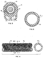
- Figures 2 and 3 are sectional views of two embodiments of the furling foil of the present invention, said views being taken perpendicular to the long axis of the foil.
- Figure 4 is a top view of the foils shown in Figures 2 and 3, with the outer portion removed.
- Figure 5 is a sectional view through line 4-4 of the preform shown in Figure 4.
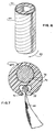
- Figure 6 is a side view of the inner portion of another embodiment of the present invention.
- Figure 7 is a sectional view of another embodiment for directly supporting and furling the free edge of a sail.
- FIG. 1 shows essential elements of conventional jib furling gear.
- a sailboat 10 has an upright mast 12 supported forwardly by a forestay 14, which is a length of wire rope or rod connected between a top portion of the mast and the bow portion of a boat.
- Furling gear may also be employed to furl other types of sails, such as staysails, supported on stays located aft of the forestay, or for supporting free edges of sails, as described herein.
- a furling foil 16 is disposed around the forestay 14 and extends substantially the entire length thereof.
- the furling foil carries the luff of a sail 18 in a conventional fashion.
- the foil has one or more longitudinal grooves 20 with restricted openings, with the luff of the sail having an elongated cross-sectional area or bead and being pulled up into the groove by a conventional halyard.
- the upper end of the foil 16 is connected to a swivel 22, and the lower end is connected to a rotary drive means, such as the illustrated drum or reel 24, which is rotated by pulling on an associated line 26 wrapped around the drum. This, in turn, causes rotation of the foil 16 around the stay 14 and the rolling up of the sail 18 around its forward edge or luff.
- the details of construction of numerous versions of furling gear of this nature are well known in the sailing industry.
- the furling foil of the present invention is of composite construction.
- the foil comprises an inner substantially flexible tube 30, an intermediate torsion resistant layer 32, and an outer cover portion or sheath 34 having one or more longitudinal grooves 20 or other sail attachment means therein.
- the inner 30 and outer 34 portions are bonded to the intermediate layer 32 to provide the composite elongated structure.
- the intermediate layer 32 while being highly torsionally resistant in combination with the other portions, is also flexible along its length.
- the intermediate layer 32 preferably comprises a plurality of reinforcing strands, bands or filaments extending in one or in two opposite helical or spiral directions around the length of the foil. These filaments, in compression and tension, oppose torsional forces exerted on the foil as a result of furling operations.
- the inner tube 30 is composed of a polymer and preferably a thermoplastic.
- the tube may be composed of a low friction material, including materials such as nylon, polyolefins, and preferably polypropylene.
- the intermediate, torque-resistant layer or sleeve 32 is then applied and bonded to the inner tube 30, as shown in Figures 4 and 5.
- the layer 32 preferably comprises high modulus filaments which are applied in a helical fashion in both rotary directions around the length of the tube. These filaments preferably comprise metal such as stainless steel, but may also comprise glass, boron, or other known filaments having high tensile strength and being flexible along their length, such as aramids.
- the filaments may be in the form of an interwoven fabric, with bundles of strands 36 in one helical direction overlapping and interwoven with bundles in the other direction in a continuous fashion.
- the fabric may be in the form of a braided or interwoven tube or sleeve heat welded to the inner tube.
- the wire is continuously braided directly around the inner tube while the wire is being heated, such as by induction heating, which causes the braided tube to fuse and permanently bond with the inner tube upon cooling. While a seperate adhesive could be employed, the direct bonding is more efficient.
- the sheath 34 may be profiled to reduce wind resistance and comprises an elongate inner cylindrical wall bonded to the outwardly facing surface of the intermediate layer 32, and having one or more external longitudinal grooves of channels 20 in a relatively thick portion of the sheath.
- the channels 20 have restricted openings to receive the luff of a sail in a conventional fashion.
- sheath 34 may be made separately and bonded to the inner portions by adhesive, it is preferable to extrude the sheath directly over the inner portion by a coextrusion process, using a die of suitable configuration, through which the inner portion and molten thermoplastic are coextruded.
- the sheath is preferably composed of a relatively hard and somewhat flexible thermoplastic material having good resistance to the sun and oxidation, such as polyvinyl chloride. Upon extrusion, the hot thermoplastic penetrates the intermediate layer 32 and upon cooling forms a permanent bond therewith. Another possible method of production is to pultrude or coextrude the reinforcing layer with the inner and outer portions.
- Figure 6 shows an inner plastic tube 62 having a single continuous band 64 of reinforcing material, such as a metal strip, applied around the tub in a helical fashion.
- band 64 of reinforcing material, such as a metal strip
- a helical or spiral reinforcing layer has the advantage that the layer is very flexible lengthwise but provides substantial torque resistance.
- the pitch of the reinforcing layer may be decreased for added torsional resistance, or increased where less resistance is needed.
- a stainless steel braid may be employed in which the braid comprises twenty-four bundles of wire, with eight wires in each bundle, and being braided at a 1.56 inch (3,96 cm) pitch. This results in a foil having less than one revolution of twist in maximum wind conditions.
- the pitch of the reinforcing layer may be varied over the length of the foil.
- the lower portion of the foil is subjected to the highest torque, and this portion may include a reinforcing layer with a lower pitch, or an extra layer.
- Figure 7 shows another embodiment in which a stay is not employed, and a free edge of a sail is carried directly by the foil. Sails such as gennakers or cruising spinnakers are flown with unsupported edges and there is no stay to support the foil or the leading edge of the sail. Hence, it is not possible to partally furl these sails by roller furling.
- the central portion of the foil may comprise a flexible line or rope 70, preferably made from high tensile strength material such as aramid.
- the spiral reinforcing layer 72 is bonded to the core 70, and the outer sheath 74 is disposed around the reinforcing layer as in the previous embodiments.
- the sheath 74 has a longitudinal channel 76 to receive a bead 78 on the edge of a sail 80.
- the foil shown in Figure 7 would be relatively small in diameter in comparison to forestay foils, but the foil would be rotated in the same for furling, such as by use of a small furling drum.
- a distinct advantage is that such sails may be partially or completely furled without the need to lower the sail.
- the resulting product has properties which are unique and highly superior to known furling foils.
- the foil can be bent along its length in a direction away from the grooved portion into the form of a coil.
- the foil does not kink during bending because the intermediate layer resists radial expansion and contraction around the inner portion and also helps to restore the foil to its straight configuration.
- the elongated foil has a high torque resisting moment and is highly resistant to torque or twisting forces around the longitudinal axis, comparable to an extruded aluminum foil of the same length and overall diameter.
- the cross-sectional dimensions of the foil may be easily designed to accommodate foils of various lengths and working loads.
- the foil is comparatively light in weight, and the outer plastic sheath and groove are not subject to damage or denting.
Landscapes
- Engineering & Computer Science (AREA)
- Life Sciences & Earth Sciences (AREA)
- Sustainable Development (AREA)
- Sustainable Energy (AREA)
- Chemical & Material Sciences (AREA)
- Combustion & Propulsion (AREA)
- Mechanical Engineering (AREA)
- Ocean & Marine Engineering (AREA)
- Ropes Or Cables (AREA)
- Shaping Of Tube Ends By Bending Or Straightening (AREA)
- Toys (AREA)
- Moulding By Coating Moulds (AREA)
Description
Claims (20)
- A furling foil (16) for furling a sail (18) around its luff and around a stay (14) of a sailing vessel (10), said furling foil (16) comprising an elongate member, said member comprising an outer flexible portion (34) of a first material having a longitudinal groove (20) therein for supporting the luff of a sail, and inner reinforcing portion (30) of a second different material bonded to said outer portion, said inner portion (30) having substantially greater torsional resistance than said outer portion, said furling foil being substantially bendable along its length without permanent distortion.
- The furling foil of claim 1 wherein said inner reinforcing portion (30) comprises a continuous filament (32) extending helically within said elongate member.
- The furling foil of claim 1 wherein said first material is a thermoplastic.
- A furling system for a sailing vessel (10) comprising a stay (14) on said sailing vessel, a furling foil (16) rotatably mounted on said stay, and a sail (18) having its forward edge supported by said furling foil (16), said furling foil comprising an inner elongate tube (30), an outer portion (34) coextensive with said inner tube, means (20) in said outer portion for supporting said sail, and reinforcing means (32) bonded between said inner tube (30) and outer portion (34) for substantially increasing the torsional resistance of said furling foil (16).
- The furling system of claim 4 wherein said reinforcing means (32) comprises a plurality of filaments (36) extending around said inner tube (30) in a helical fashion.
- The furling system of claim 4 wherein said reinforcing means (62) comprises a helical metal band (64).
- The furling system of claim 5 wherein said plurality of filaments (36) extend in two opposite helical directions around said inner tube (30).
- The furling system of claim 3 wherein said plurality of filaments (36) are braided around said inner tube.
- The furling system of claim 8 wherein said plurality of filaments comprise metal filaments.
- The furling system of claim 9 wherein said inner elongate tube (30) comprises a thermoplastic material and said plurality of filaments are heat bonded to said inner tube.
- The furling system of claim 4 wherein said outer portion (34) comprises a thermoplastic material extruded over said reinforcing means (32).
- The furling system of claim 4 wherein means (20) are connected to said furling foil for rotation thereof.
- A furling system for a sailboat (10) wherein said furling system comprises a stay (14), an elongate improved furling foil (16) having a central channel extending around a stay (14), external means (20) on said furling foil for supporting the edge of a sail (18), and means (24) for rotating said furling foil around said stay, wherein said furling foil comprises a inner portion (30) having said central channel and an outer portion (34) having said eternal means (20), said inner (30) and outer (34) portions comprising flexible plastic materials, and an intermediate reinforcing portion (32, 72) bonded between said inner (30) and outer (34) portions, said intermediate portion (32, 72) providing a substantial increase in torsional resistance of said furling foil (16) while allowing said foil to be bent lengthwise in the form of a coil without permanent distortion.
- The furling system of claim 13 wherein said inner portion (30) is composed of polypropylene.
- The furling system of claim 13 wherein said outer (34, 74) portion comprises a thermoplastic extruded polymer.
- The furling system of claim 13 wherein said intermediate reinforcing portion (32) comprises high tensile braided filaments (36).
- The furling system of claim 16 wherein said filaments are steel wire.
- A furling foil (16) for furling a sail (18) around an edge of the sail, said furling foil composing an elongate inner flexible member (30), a torsion resistant layer (32, 72) disposed around at least a portion of said elongate inner member (30), said torsion resistant layer (32, 72) being longitudinally flexible, an outer flexible portion (34, 74) disposed around said torsion resistant layer, and a longitudinal groove means (20, 76) for receiving and supporting the edge of a sail.
- The furling foil of claim 18 wherein said torsion resistant layer (62) comprises helical windings (64).
- The furling foil of claim 18 wherein said inner flexible member comprises a rope.
Applications Claiming Priority (2)
| Application Number | Priority Date | Filing Date | Title |
|---|---|---|---|
| US402919 | 1995-03-13 | ||
| US08/402,919 US5463970A (en) | 1995-03-13 | 1995-03-13 | Furling foil for sailing vessel |
Publications (2)
| Publication Number | Publication Date |
|---|---|
| EP0732260A1 EP0732260A1 (en) | 1996-09-18 |
| EP0732260B1 true EP0732260B1 (en) | 1998-12-16 |
Family
ID=23593814
Family Applications (1)
| Application Number | Title | Priority Date | Filing Date |
|---|---|---|---|
| EP95305679A Expired - Lifetime EP0732260B1 (en) | 1995-03-13 | 1995-08-15 | Furling foil for sailing vessel |
Country Status (5)
| Country | Link |
|---|---|
| US (1) | US5463970A (en) |
| EP (1) | EP0732260B1 (en) |
| AU (1) | AU2853995A (en) |
| CA (1) | CA2156099A1 (en) |
| DE (1) | DE69506685T2 (en) |
Families Citing this family (24)
| Publication number | Priority date | Publication date | Assignee | Title |
|---|---|---|---|---|
| GB2355703B (en) * | 1999-10-29 | 2003-04-23 | Robert Paul Helyar | Dinghy head-sail reefing system |
| JP2004520539A (en) * | 2000-07-28 | 2004-07-08 | ブリガム・ヤング・ユニバーシティ | Iso-truss structure |
| US6668741B1 (en) * | 2000-12-07 | 2003-12-30 | Steve Curtiss | High performance sailing craft |
| ITMI20010148U1 (en) * | 2001-03-15 | 2002-09-16 | Greghi Renzo | SAIL WINDING DEVICE |
| TW565647B (en) * | 2001-08-17 | 2003-12-11 | Univ Brigham Young | Method and apparatus for fabricating complex, composite structures from continuous fibers |
| GB2380984B (en) * | 2001-10-15 | 2003-08-27 | Boyce Spars Holdings Ltd | A method of manufacturing an elongate structural member and a method of rigging a boat |
| TWI225531B (en) * | 2002-09-04 | 2004-12-21 | Univ Brigham Young | Three-dimensional grid panel |
| US6848381B2 (en) * | 2003-02-12 | 2005-02-01 | Georg K. Thomas | Tension rod constructions and method of making |
| US6886484B2 (en) * | 2003-02-12 | 2005-05-03 | Georg K. Thomas | Composite tension rod terminal systems |
| US6895882B1 (en) * | 2004-03-03 | 2005-05-24 | Cruising Design, Inc. | Light-weight code-zero headsail system |
| ITMI20040589A1 (en) * | 2004-03-25 | 2004-06-25 | Renzo Greghi | SAIL WINDING DEVICE |
| US7262353B2 (en) * | 2004-11-16 | 2007-08-28 | John Bartholomew | Braided composite stringed instrument bow |
| WO2008091230A1 (en) * | 2007-01-26 | 2008-07-31 | Agency For Science, Technology And Research | A radio frequency identification transceiver |
| US7795515B2 (en) * | 2007-03-15 | 2010-09-14 | John Bartholomew | Laminated stringed instrument bow |
| EP2335138A4 (en) * | 2008-08-15 | 2012-12-19 | Qualcomm Inc | Enhanced multi-touch detection |
| WO2010019966A2 (en) * | 2008-08-15 | 2010-02-18 | Sigma-Tek, Llc | Method & system for forming composite lattice support structures |
| US9301624B2 (en) | 2012-08-07 | 2016-04-05 | Thorley Industries Llc | Foldable play yard apparatus including a clamp and a method of attaching a flexible sheet to the clamp |
| BE1021747B1 (en) | 2013-07-05 | 2016-01-15 | Building A Future Foundation | CABLE AND METHOD OF PRODUCING SUCH CABLE |
| AU2015211146A1 (en) | 2014-01-28 | 2016-08-11 | Harken, Incorporated | Top down furling system |
| US10584491B2 (en) | 2017-03-06 | 2020-03-10 | Isotruss Industries Llc | Truss structure |
| US10180000B2 (en) | 2017-03-06 | 2019-01-15 | Isotruss Industries Llc | Composite lattice beam |
| US10336423B2 (en) * | 2017-11-09 | 2019-07-02 | Nrob, Llc | Top down furling system and method |
| USD895157S1 (en) | 2018-03-06 | 2020-09-01 | IsoTruss Indsutries LLC | Longitudinal beam |
| USD896401S1 (en) | 2018-03-06 | 2020-09-15 | Isotruss Industries Llc | Beam |
Family Cites Families (12)
| Publication number | Priority date | Publication date | Assignee | Title |
|---|---|---|---|---|
| US3802373A (en) * | 1972-01-20 | 1974-04-09 | R Lagerquist | Encapsulating sleeve for headstay of a sailboat |
| USRE31829E (en) * | 1972-08-21 | 1985-02-12 | Two groove headstay | |
| US3872816A (en) | 1973-07-05 | 1975-03-25 | Edmund A Cutts | Rotatable stay for sail furling gear |
| FR2243862B1 (en) * | 1973-09-18 | 1976-06-18 | Bernard Bernard | |
| US4267790A (en) * | 1978-04-20 | 1981-05-19 | Hood Ralph S | Sail furling and reefing apparatus |
| US4248281A (en) * | 1979-06-18 | 1981-02-03 | Hood Enterprises, Inc. | Roll-reefing jib sail |
| FR2539099B1 (en) * | 1983-01-07 | 1988-06-24 | Normandie Voiles | WINDING TUBE AND SAIL REEL HAVING SUCH A TUBE |
| GB2133363B (en) * | 1983-01-13 | 1986-04-23 | Proengin | Reefing sails |
| CH657101A5 (en) * | 1984-07-27 | 1986-08-15 | Nirvana Espar Systems Sa | SAIL FURLER FOR BOAT. |
| US4619216A (en) * | 1984-10-05 | 1986-10-28 | Crear Iii William | Sailboat luff system |
| US4721117A (en) * | 1986-04-25 | 1988-01-26 | Advanced Cardiovascular Systems, Inc. | Torsionally stabilized guide wire with outer jacket |
| US4821664A (en) | 1987-06-12 | 1989-04-18 | Cruising Design, Inc. | Furling stay cover |
-
1995
- 1995-03-13 US US08/402,919 patent/US5463970A/en not_active Expired - Fee Related
- 1995-08-14 AU AU28539/95A patent/AU2853995A/en not_active Abandoned
- 1995-08-15 CA CA002156099A patent/CA2156099A1/en not_active Abandoned
- 1995-08-15 EP EP95305679A patent/EP0732260B1/en not_active Expired - Lifetime
- 1995-08-15 DE DE69506685T patent/DE69506685T2/en not_active Expired - Fee Related
Also Published As
| Publication number | Publication date |
|---|---|
| US5463970A (en) | 1995-11-07 |
| CA2156099A1 (en) | 1996-09-14 |
| DE69506685D1 (en) | 1999-01-28 |
| DE69506685T2 (en) | 1999-06-17 |
| AU2853995A (en) | 1996-09-26 |
| EP0732260A1 (en) | 1996-09-18 |
Similar Documents
| Publication | Publication Date | Title |
|---|---|---|
| US5463970A (en) | Furling foil for sailing vessel | |
| US4248281A (en) | Roll-reefing jib sail | |
| US9694890B2 (en) | Top down furling system | |
| JP2009529313A5 (en) | ||
| US4503797A (en) | Sail rolling and storing device | |
| US4269134A (en) | Sailboat with universal roll furling sail housing | |
| AT504907B1 (en) | ROLL REFILL FOR SAILING SHIPS | |
| US4267790A (en) | Sail furling and reefing apparatus | |
| US4196687A (en) | Roller reefing system | |
| US5014637A (en) | Roller reefing system for sails and the like | |
| US7975635B2 (en) | Furling and unfurling device for asymmetric sails | |
| US4821664A (en) | Furling stay cover | |
| FI78874B (en) | SEGELFARTYG. | |
| US4526122A (en) | Load distribution and anti-sag means for luff furling sails | |
| JPH01500579A (en) | Reinforcing member for elongated objects including multiple strips and methods for manufacturing and using the same | |
| USRE31829E (en) | Two groove headstay | |
| US5617807A (en) | Carbon fiber spar and method of making | |
| US3872816A (en) | Rotatable stay for sail furling gear | |
| US5632215A (en) | Roller reefing boom system | |
| EP1188663B1 (en) | Furling sail system | |
| US4637334A (en) | Roller furling element for boats equipped with sails | |
| US6892660B2 (en) | Furling sail and means for turning mast | |
| US4606292A (en) | Apparatus for reefing sails on a boat and specially-designed boom including such an apparatus | |
| US6895882B1 (en) | Light-weight code-zero headsail system | |
| US3851608A (en) | Stream-stay |
Legal Events
| Date | Code | Title | Description |
|---|---|---|---|
| PUAI | Public reference made under article 153(3) epc to a published international application that has entered the european phase |
Free format text: ORIGINAL CODE: 0009012 |
|
| AK | Designated contracting states |
Kind code of ref document: A1 Designated state(s): DE FR GB IT NL SE |
|
| 17P | Request for examination filed |
Effective date: 19970131 |
|
| GRAG | Despatch of communication of intention to grant |
Free format text: ORIGINAL CODE: EPIDOS AGRA |
|
| 17Q | First examination report despatched |
Effective date: 19980223 |
|
| GRAG | Despatch of communication of intention to grant |
Free format text: ORIGINAL CODE: EPIDOS AGRA |
|
| GRAH | Despatch of communication of intention to grant a patent |
Free format text: ORIGINAL CODE: EPIDOS IGRA |
|
| GRAH | Despatch of communication of intention to grant a patent |
Free format text: ORIGINAL CODE: EPIDOS IGRA |
|
| GRAA | (expected) grant |
Free format text: ORIGINAL CODE: 0009210 |
|
| AK | Designated contracting states |
Kind code of ref document: B1 Designated state(s): DE FR GB IT NL SE |
|
| REF | Corresponds to: |
Ref document number: 69506685 Country of ref document: DE Date of ref document: 19990128 |
|
| ET | Fr: translation filed | ||
| ITF | It: translation for a ep patent filed | ||
| PLBE | No opposition filed within time limit |
Free format text: ORIGINAL CODE: 0009261 |
|
| STAA | Information on the status of an ep patent application or granted ep patent |
Free format text: STATUS: NO OPPOSITION FILED WITHIN TIME LIMIT |
|
| 26N | No opposition filed | ||
| PGFP | Annual fee paid to national office [announced via postgrant information from national office to epo] |
Ref country code: NL Payment date: 20000724 Year of fee payment: 6 |
|
| PGFP | Annual fee paid to national office [announced via postgrant information from national office to epo] |
Ref country code: DE Payment date: 20010719 Year of fee payment: 7 |
|
| PGFP | Annual fee paid to national office [announced via postgrant information from national office to epo] |
Ref country code: GB Payment date: 20010720 Year of fee payment: 7 |
|
| REG | Reference to a national code |
Ref country code: GB Ref legal event code: IF02 |
|
| PG25 | Lapsed in a contracting state [announced via postgrant information from national office to epo] |
Ref country code: NL Free format text: LAPSE BECAUSE OF NON-PAYMENT OF DUE FEES Effective date: 20020301 |
|
| NLV4 | Nl: lapsed or anulled due to non-payment of the annual fee |
Effective date: 20020301 |
|
| PGFP | Annual fee paid to national office [announced via postgrant information from national office to epo] |
Ref country code: FR Payment date: 20020717 Year of fee payment: 8 |
|
| PGFP | Annual fee paid to national office [announced via postgrant information from national office to epo] |
Ref country code: SE Payment date: 20020718 Year of fee payment: 8 |
|
| PG25 | Lapsed in a contracting state [announced via postgrant information from national office to epo] |
Ref country code: GB Free format text: LAPSE BECAUSE OF NON-PAYMENT OF DUE FEES Effective date: 20020815 |
|
| PG25 | Lapsed in a contracting state [announced via postgrant information from national office to epo] |
Ref country code: DE Free format text: LAPSE BECAUSE OF NON-PAYMENT OF DUE FEES Effective date: 20030301 |
|
| GBPC | Gb: european patent ceased through non-payment of renewal fee |
Effective date: 20020815 |
|
| PG25 | Lapsed in a contracting state [announced via postgrant information from national office to epo] |
Ref country code: SE Free format text: LAPSE BECAUSE OF NON-PAYMENT OF DUE FEES Effective date: 20030816 |
|
| EUG | Se: european patent has lapsed | ||
| PG25 | Lapsed in a contracting state [announced via postgrant information from national office to epo] |
Ref country code: FR Free format text: LAPSE BECAUSE OF NON-PAYMENT OF DUE FEES Effective date: 20040430 |
|
| REG | Reference to a national code |
Ref country code: FR Ref legal event code: ST |
|
| PG25 | Lapsed in a contracting state [announced via postgrant information from national office to epo] |
Ref country code: IT Free format text: LAPSE BECAUSE OF NON-PAYMENT OF DUE FEES;WARNING: LAPSES OF ITALIAN PATENTS WITH EFFECTIVE DATE BEFORE 2007 MAY HAVE OCCURRED AT ANY TIME BEFORE 2007. THE CORRECT EFFECTIVE DATE MAY BE DIFFERENT FROM THE ONE RECORDED. Effective date: 20050815 |