EP0732153A2 - Device for tonsionally vibrating a rotating shaft - Google Patents
Device for tonsionally vibrating a rotating shaft Download PDFInfo
- Publication number
- EP0732153A2 EP0732153A2 EP96103759A EP96103759A EP0732153A2 EP 0732153 A2 EP0732153 A2 EP 0732153A2 EP 96103759 A EP96103759 A EP 96103759A EP 96103759 A EP96103759 A EP 96103759A EP 0732153 A2 EP0732153 A2 EP 0732153A2
- Authority
- EP
- European Patent Office
- Prior art keywords
- shaft
- coupled
- supporting elements
- constituted
- springs
- Prior art date
- Legal status (The legal status is an assumption and is not a legal conclusion. Google has not performed a legal analysis and makes no representation as to the accuracy of the status listed.)
- Granted
Links
Images


Classifications
-
- B—PERFORMING OPERATIONS; TRANSPORTING
- B06—GENERATING OR TRANSMITTING MECHANICAL VIBRATIONS IN GENERAL
- B06B—METHODS OR APPARATUS FOR GENERATING OR TRANSMITTING MECHANICAL VIBRATIONS OF INFRASONIC, SONIC, OR ULTRASONIC FREQUENCY, e.g. FOR PERFORMING MECHANICAL WORK IN GENERAL
- B06B1/00—Methods or apparatus for generating mechanical vibrations of infrasonic, sonic, or ultrasonic frequency
- B06B1/10—Methods or apparatus for generating mechanical vibrations of infrasonic, sonic, or ultrasonic frequency making use of mechanical energy
-
- Y—GENERAL TAGGING OF NEW TECHNOLOGICAL DEVELOPMENTS; GENERAL TAGGING OF CROSS-SECTIONAL TECHNOLOGIES SPANNING OVER SEVERAL SECTIONS OF THE IPC; TECHNICAL SUBJECTS COVERED BY FORMER USPC CROSS-REFERENCE ART COLLECTIONS [XRACs] AND DIGESTS
- Y10—TECHNICAL SUBJECTS COVERED BY FORMER USPC
- Y10T—TECHNICAL SUBJECTS COVERED BY FORMER US CLASSIFICATION
- Y10T74/00—Machine element or mechanism
- Y10T74/19—Gearing
- Y10T74/19633—Yieldability in gear trains
-
- Y—GENERAL TAGGING OF NEW TECHNOLOGICAL DEVELOPMENTS; GENERAL TAGGING OF CROSS-SECTIONAL TECHNOLOGIES SPANNING OVER SEVERAL SECTIONS OF THE IPC; TECHNICAL SUBJECTS COVERED BY FORMER USPC CROSS-REFERENCE ART COLLECTIONS [XRACs] AND DIGESTS
- Y10—TECHNICAL SUBJECTS COVERED BY FORMER USPC
- Y10T—TECHNICAL SUBJECTS COVERED BY FORMER US CLASSIFICATION
- Y10T74/00—Machine element or mechanism
- Y10T74/19—Gearing
- Y10T74/19642—Directly cooperating gears
- Y10T74/19698—Spiral
- Y10T74/19828—Worm
Definitions
- the present invention relates to a device for subjecting a shaft to a combined simple rotation and alternating rotation of limited extent about its own axis.
- This so-called balling and burlapping operation currently entails the use of an arc-shaped blade that is subjected to a combined simple rotation and alternating rotation of limited extent about its own axis.
- the simple rotation combined with the alternating vibratory motion, allows the blade to penetrate the soil and to isolate the sod from said soil.
- Each one of the two movements is actuated by corresponding actuation means, for example a hydraulic motor for rotary motion and a torsional oscillation generator for vibratory motion.
- actuation means for example a hydraulic motor for rotary motion and a torsional oscillation generator for vibratory motion.
- a principal aim of the present invention is to provide a device for subjecting a shaft to a combined simple rotation and alternating rotation of limited extent about its own axis that is not subject to breakages due to fatigue of parts during use.
- a consequent primary object is to provide a device that can be conveniently installed on equipment for performing the balling and burlapping of plants.
- Another object is to provide a device that can be manufactured with conventional equipment and facilities.
- a device comprising elastic means that are arranged diametrically opposite with respect to a shaft that is coupled to a generator of torsional vibrations, said elastic means being rigidly coupled between first supporting elements that rotate with said shaft and second supporting elements that are rigidly coupled to a gear system that is freely mounted on said shaft and is coupled to means for actuating rotation.
- a shaft 11 is rotatably coupled to a frame 10, and a curved blade, not shown in the figures, for performing for example the balling and burlapping of plants is conveniently fixed on the head 11a of said shaft.
- Said shaft 11 is subjected to a combined motion that includes a simple rotation, by means of a hydraulic motor 12 and of a worm gear reduction unit 13, and an alternating rotation of limited extent, by means of a torsional vibration generator 14.
- the device 15 described hereinafter comprises in this case four cylindrical helical springs 16 arranged in parallel pairs and in diametrically opposite positions so as to substantially surround the shaft 11.
- the springs 16 are rigidly coupled between first supporting elements, generally designated by the reference numeral 17, and second supporting elements, generally designated by the reference numeral 18.
- the first supporting elements 17 are constituted, in this case, by a rocker 19 with two arms 20 extending in opposite directions; said rocker 19 is rigidly coupled coaxially, by means of a splined coupling, to the shaft 11.
- the second supporting elements 18 are constituted, in this embodiment, by wings 21 extending axially, in diametrically opposite positions, from the flange-fitted end 22 of a shaped tubular element 23 that is fixed by means of bolts 24 to a ring gear 25 of the reduction unit 13.
- the tubular element 23 and the ring gear 25 are coaxial to the shaft 11 upon assembly; the tubular element 23 is furthermore associated with said shaft 11 by bearing systems generally designated by the reference numeral 26.
- the reduction unit 13 constituted by the ring gear 25 and by the worm gear 27 receives its driving motion from the hydraulic motor 12.
- each one of the springs 16 has an end that is fixed to a corresponding wing 21 by means of a corresponding threaded element 28, whereas the other end is fixed to a dome-shaped part 29 that is slidingly coupled to an appropriately complementarily shaped region 30 of a corresponding one of the arms 20.
- the threaded element 28 accommodated in a corresponding seat 31 formed in the corresponding wing 21 engages a bush 32 that is accommodated snugly and coaxially inside the respective spring 16.
- Coupling between the dome-shaped part 29 and the corresponding complementarily shaped region 30 is ensured by a rod-like element 33 that is pivoted in a cavity 34 formed in the corresponding arm 20 and, upon assembly, is inserted in a hole 35 formed in the dome-shaped part 29, where said rod-like element 33, by having an end that can open in a fork-like manner, determines the anchoring of said end to the dome-shaped part 29.
- the materials employed may be any according to the requirements.
Abstract
Description
- The present invention relates to a device for subjecting a shaft to a combined simple rotation and alternating rotation of limited extent about its own axis.
- It is particularly but not exclusively applicable to a mechanical system for eradicating plants.
- In order to remove plants from the soil it is usually necessary to ensure that an appropriate sod of said soil remains together with the roots.
- This so-called balling and burlapping operation currently entails the use of an arc-shaped blade that is subjected to a combined simple rotation and alternating rotation of limited extent about its own axis.
- The simple rotation, combined with the alternating vibratory motion, allows the blade to penetrate the soil and to isolate the sod from said soil.
- Each one of the two movements is actuated by corresponding actuation means, for example a hydraulic motor for rotary motion and a torsional oscillation generator for vibratory motion.
- The problem currently affecting these devices is due to breakages which occur in the parts associating the shaft that supports the blade with the actuation means.
- A principal aim of the present invention is to provide a device for subjecting a shaft to a combined simple rotation and alternating rotation of limited extent about its own axis that is not subject to breakages due to fatigue of parts during use.
- A consequent primary object is to provide a device that can be conveniently installed on equipment for performing the balling and burlapping of plants.
- Another object is to provide a device that can be manufactured with conventional equipment and facilities.
- With this aim, these and other objects in view, there is provided a device comprising elastic means that are arranged diametrically opposite with respect to a shaft that is coupled to a generator of torsional vibrations, said elastic means being rigidly coupled between first supporting elements that rotate with said shaft and second supporting elements that are rigidly coupled to a gear system that is freely mounted on said shaft and is coupled to means for actuating rotation.
- Further characteristics and advantages of the invention will become apparent from the following detailed description of an embodiment thereof, illustrated only by way of non-limitative example in the accompanying drawings, wherein:
- figure 1 is an external perspective view of the device;
- figure 2 is a perspective view of the elements located inside the device of figure 1;
- figure 3 is a front view of the elements of figure 2;
- figure 4 is a side view of the elements of figure 2;
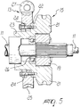
- figure 5 is a sectional view of the elements of figure 2.
- With reference to the above figures, a
shaft 11 is rotatably coupled to aframe 10, and a curved blade, not shown in the figures, for performing for example the balling and burlapping of plants is conveniently fixed on thehead 11a of said shaft. - Said
shaft 11 is subjected to a combined motion that includes a simple rotation, by means of ahydraulic motor 12 and of a wormgear reduction unit 13, and an alternating rotation of limited extent, by means of atorsional vibration generator 14. - The simultaneous application of the simple rotation and of the alternating rotation to the
shaft 11 is possible by means of adevice 15 according to the invention that kinematically connects thereduction unit 13 to theshaft 11, allowing appropriately damped oscillations between them. - The
device 15 described hereinafter comprises in this case four cylindricalhelical springs 16 arranged in parallel pairs and in diametrically opposite positions so as to substantially surround theshaft 11. - The
springs 16 are rigidly coupled between first supporting elements, generally designated by thereference numeral 17, and second supporting elements, generally designated by the reference numeral 18. - The first supporting
elements 17 are constituted, in this case, by arocker 19 with twoarms 20 extending in opposite directions; saidrocker 19 is rigidly coupled coaxially, by means of a splined coupling, to theshaft 11. - The second supporting elements 18 are constituted, in this embodiment, by
wings 21 extending axially, in diametrically opposite positions, from the flange-fittedend 22 of a shapedtubular element 23 that is fixed by means ofbolts 24 to aring gear 25 of thereduction unit 13. - The
tubular element 23 and thering gear 25 are coaxial to theshaft 11 upon assembly; thetubular element 23 is furthermore associated with saidshaft 11 by bearing systems generally designated by thereference numeral 26. - The
reduction unit 13 constituted by thering gear 25 and by theworm gear 27 receives its driving motion from thehydraulic motor 12. - As regards the
device 15, each one of thesprings 16 has an end that is fixed to acorresponding wing 21 by means of a corresponding threadedelement 28, whereas the other end is fixed to a dome-shaped part 29 that is slidingly coupled to an appropriately complementarilyshaped region 30 of a corresponding one of thearms 20. - More specifically, the threaded
element 28 accommodated in acorresponding seat 31 formed in the corresponding wing 21 (in this case, twoseats 31 lying substantially at right angles to each other are formed in each wing 21), engages abush 32 that is accommodated snugly and coaxially inside therespective spring 16. - Coupling between the dome-
shaped part 29 and the corresponding complementarilyshaped region 30 is ensured by a rod-like element 33 that is pivoted in acavity 34 formed in thecorresponding arm 20 and, upon assembly, is inserted in ahole 35 formed in the dome-shaped part 29, where said rod-like element 33, by having an end that can open in a fork-like manner, determines the anchoring of said end to the dome-shaped part 29. - In practice it has been observed that the above described device has achieved the intended aim and objects of the present invention.
- Fatigue tests have in fact shown that parts breakages no longer occur.
- In practice, the materials employed, so long as they are compatible with the contingent use, as well as the dimensions, may be any according to the requirements.
- Where technical features mentioned in any claim are followed by reference signs, those reference signs have been included for the sole purpose of increasing the intelligibility of the claims and accordingly, such reference signs do not have any limiting effect on the interpretation of each element identified by way of example by such reference signs.
Claims (11)
- Device for subjecting a shaft to a combined simple rotation and alternating rotation of limited extent about its own axis, characterized in that it comprises elastic means that are arranged diametrically opposite with respect to a shaft that is coupled to a generator of torsional vibrations, said elastic means being rigidly coupled between first supporting elements that rotate with said shaft and second supporting elements that are rigidly coupled to a gear system that is freely mounted on said shaft and is coupled to means for actuating rotation.
- Device according to claim 1, characterized in that said elastic means are constituted by cylindrical helical springs arranged in parallel pairs and located in diametrically opposite positions.
- Device according to claim 1, characterized in that said first supporting elements are constituted by a rocker, with two arms extending in opposite directions, which is coupled coaxially to said shaft by a splined coupling.
- Device according to claim 1, characterized in that said second supporting elements are constituted by wings extending from said gear system.
- Device according to claim 2, characterized in that each one of said springs is arranged between a corresponding arm of said rocker and a corresponding wing.
- Device according to claim 5, characterized in that each one of said springs has one end that is fixed to the corresponding said wing, and an other end connected and articulated to the corresponding said arm.
- Device according to claim 6, characterized in that each one of said springs has an end that is articulated to the corresponding said arm or to the corresponding said wing, said end being fixed to a dome-shaped part that is in turn slidingly coupled to an appropriately complementarily shaped region of a corresponding said arm or of a corresponding said wing.
- Device according to claim 1, characterized in that said gear system is constituted by a worm gear reduction unit.
- Device according to claim 4, characterized in that said wings constituting said second supporting elements extend from the flange-fitted end of a tubular element that is fixed to said ring gear by means of bolts.
- Device according to claim 9, characterized in that said tubular element is associated with said shaft by means of bearing systems.
- Device according to claim 1, characterized in that said rotation actuation means are constituted by a hydraulic motor that is coupled to said worm gear reduction unit.
Applications Claiming Priority (2)
| Application Number | Priority Date | Filing Date | Title |
|---|---|---|---|
| ITPD950018U | 1995-03-14 | ||
| IT1995PD000018U IT239102Y1 (en) | 1995-03-14 | 1995-03-14 | DEVICE FOR SUBJECTING A TREE TO A COMBINED MOVEMENT SIMPLE AND ALTERNATE ROTATION, OF REDUCED AMPLITUDE, |
Publications (3)
| Publication Number | Publication Date |
|---|---|
| EP0732153A2 true EP0732153A2 (en) | 1996-09-18 |
| EP0732153A3 EP0732153A3 (en) | 1997-07-02 |
| EP0732153B1 EP0732153B1 (en) | 1999-12-01 |
Family
ID=11390902
Family Applications (1)
| Application Number | Title | Priority Date | Filing Date |
|---|---|---|---|
| EP96103759A Expired - Lifetime EP0732153B1 (en) | 1995-03-14 | 1996-03-11 | Device for torsionally vibrating a rotating shaft |
Country Status (6)
| Country | Link |
|---|---|
| US (1) | US5771744A (en) |
| EP (1) | EP0732153B1 (en) |
| CA (1) | CA2171794A1 (en) |
| DE (1) | DE69605340T2 (en) |
| ES (1) | ES2140737T3 (en) |
| IT (1) | IT239102Y1 (en) |
Cited By (3)
| Publication number | Priority date | Publication date | Assignee | Title |
|---|---|---|---|---|
| EP0791406A1 (en) * | 1996-02-20 | 1997-08-27 | Holmac S.a.s. di Gastaldi Christian & C. | Device for torsionally vibrating a rotating shaft |
| CN104653738A (en) * | 2015-02-11 | 2015-05-27 | 曲绍毅 | Worm wheel worn rod decelerator capable of vibrating |
| CN111570246A (en) * | 2020-05-25 | 2020-08-25 | 南京工程学院 | Intermittent axial torsion combined type mechanical torsional vibration table |
Families Citing this family (8)
| Publication number | Priority date | Publication date | Assignee | Title |
|---|---|---|---|---|
| US6135889A (en) * | 1996-02-20 | 2000-10-24 | Holmac S.A.S. Di Gastaldi Christian & C. | Device for subjecting a shaft to a combined simple rotation and alternating rotation of limited extent about its own axis |
| US5905154A (en) * | 1996-06-10 | 1999-05-18 | American Cyanamid Company | Process for the preparation of 5-(alkoxymethyl)-2,3-pyridinedicarboximide compounds |
| US6408572B1 (en) * | 1998-06-03 | 2002-06-25 | Mitsuba Corporation | Driving gear |
| JP2001271903A (en) * | 2000-01-17 | 2001-10-05 | Honda Motor Co Ltd | Power transmission device for work machine |
| WO2010104640A1 (en) * | 2009-03-10 | 2010-09-16 | Illinois Tool Works Inc. | Hybrid enveloping spiroid and worm gear |
| US20130061704A1 (en) * | 2011-09-09 | 2013-03-14 | Illinois Tool Works Inc. | Enveloping spiroid gear assemblies and method of manufacturing the same |
| US9234549B2 (en) * | 2013-09-13 | 2016-01-12 | Paladin Brands Group, Inc. | Torsional coupling for a mobile attachment device |
| US20160091052A1 (en) * | 2014-09-25 | 2016-03-31 | Moatech Co., Ltd. | Actuator and electronic equipment having the same |
Citations (5)
| Publication number | Priority date | Publication date | Assignee | Title |
|---|---|---|---|---|
| GB418783A (en) * | 1933-10-02 | 1934-10-31 | Cesare Fontana | Improvements in or relating to variable speed gearing |
| FR775014A (en) * | 1934-06-18 | 1934-12-18 | Dynamometric and progressive speed change | |
| US2005974A (en) * | 1931-10-24 | 1935-06-25 | Packard Motor Car Co | Power transmission system |
| FR1148842A (en) * | 1956-03-05 | 1957-12-16 | Gear switch | |
| FR1604413A (en) * | 1968-11-28 | 1971-11-08 |
Family Cites Families (7)
| Publication number | Priority date | Publication date | Assignee | Title |
|---|---|---|---|---|
| US1510943A (en) * | 1924-04-10 | 1924-10-07 | Kjelsberg Olaf | Resilient gear wheel |
| US3461969A (en) * | 1966-05-20 | 1969-08-19 | Bodine Albert G | Sonic subsurface soil cultivator |
| US4616713A (en) * | 1984-11-29 | 1986-10-14 | Shattuck Thomas G | Blade adjustment device for sod cutting machine |
| JPS6420428A (en) * | 1987-07-15 | 1989-01-24 | Fujitsu Ltd | Formation of acicular member |
| US4871027A (en) * | 1988-07-07 | 1989-10-03 | J. I. Case Company | Multiple-edge sod cutter for vibratory plow |
| FR2655115B1 (en) * | 1989-11-30 | 1993-01-22 | Valeo | VIBRATION DAMPER, ESPECIALLY FOR A MOTOR VEHICLE. |
| JPH0646089Y2 (en) * | 1990-02-02 | 1994-11-24 | 原田工業株式会社 | Electric telescopic antenna drive |
-
1995
- 1995-03-14 IT IT1995PD000018U patent/IT239102Y1/en active
-
1996
- 1996-03-11 DE DE69605340T patent/DE69605340T2/en not_active Expired - Fee Related
- 1996-03-11 EP EP96103759A patent/EP0732153B1/en not_active Expired - Lifetime
- 1996-03-11 ES ES96103759T patent/ES2140737T3/en not_active Expired - Lifetime
- 1996-03-12 US US08/614,414 patent/US5771744A/en not_active Expired - Lifetime
- 1996-03-14 CA CA002171794A patent/CA2171794A1/en not_active Abandoned
Patent Citations (5)
| Publication number | Priority date | Publication date | Assignee | Title |
|---|---|---|---|---|
| US2005974A (en) * | 1931-10-24 | 1935-06-25 | Packard Motor Car Co | Power transmission system |
| GB418783A (en) * | 1933-10-02 | 1934-10-31 | Cesare Fontana | Improvements in or relating to variable speed gearing |
| FR775014A (en) * | 1934-06-18 | 1934-12-18 | Dynamometric and progressive speed change | |
| FR1148842A (en) * | 1956-03-05 | 1957-12-16 | Gear switch | |
| FR1604413A (en) * | 1968-11-28 | 1971-11-08 |
Cited By (4)
| Publication number | Priority date | Publication date | Assignee | Title |
|---|---|---|---|---|
| EP0791406A1 (en) * | 1996-02-20 | 1997-08-27 | Holmac S.a.s. di Gastaldi Christian & C. | Device for torsionally vibrating a rotating shaft |
| CN104653738A (en) * | 2015-02-11 | 2015-05-27 | 曲绍毅 | Worm wheel worn rod decelerator capable of vibrating |
| CN111570246A (en) * | 2020-05-25 | 2020-08-25 | 南京工程学院 | Intermittent axial torsion combined type mechanical torsional vibration table |
| CN111570246B (en) * | 2020-05-25 | 2021-06-01 | 南京工程学院 | Intermittent axial torsion combined type mechanical torsional vibration table |
Also Published As
| Publication number | Publication date |
|---|---|
| ITPD950018V0 (en) | 1995-03-14 |
| EP0732153B1 (en) | 1999-12-01 |
| IT239102Y1 (en) | 2001-02-19 |
| DE69605340T2 (en) | 2000-07-13 |
| ITPD950018U1 (en) | 1996-09-14 |
| CA2171794A1 (en) | 1996-09-15 |
| EP0732153A3 (en) | 1997-07-02 |
| ES2140737T3 (en) | 2000-03-01 |
| DE69605340D1 (en) | 2000-01-05 |
| US5771744A (en) | 1998-06-30 |
Similar Documents
| Publication | Publication Date | Title |
|---|---|---|
| EP0732153B1 (en) | Device for torsionally vibrating a rotating shaft | |
| US5305738A (en) | Massage device | |
| EP3149356B1 (en) | Rotation damper | |
| EP1725373B9 (en) | Wobble drive | |
| EP0413168B1 (en) | Wet-shaver | |
| DE4006608A1 (en) | SEAT FURNITURE WITH A SWIVELING SEAT | |
| NO833832L (en) | TUNED GYROSCOPE WITH DYNAMIC ABSORBERS | |
| CH704541A2 (en) | Rotor blade coupling device. | |
| DE69820920T2 (en) | Tuned vibration damper with double bending elements | |
| EP0142205A1 (en) | A cover construction for a steam peeling apparatus | |
| CN105966613A (en) | Antivibration suspension system for tie bar of suspension power transmission gearbox, suspension structure, and an aircraft | |
| FR2787762A1 (en) | Anti-vibration torsion spring suspension for helicopter has levers linked to transmission box by torsion spring | |
| KR100710640B1 (en) | Reducer for ice crusher | |
| EP3646988A1 (en) | Support, machine and process for surface finishing | |
| DE2742560C2 (en) | Torsional vibration damper | |
| EP3146231A1 (en) | Rotation damper | |
| CA2285898C (en) | Face gear transmission assembly, in particular for aircraft application | |
| WO2016023616A1 (en) | Drive unit for a strapping device | |
| US4778340A (en) | Main helicopter rotor | |
| EP0791406B1 (en) | Device for torsionally vibrating a rotating shaft | |
| GB2199295A (en) | Helicopter rotor | |
| DE102005027764B4 (en) | Vibration generating device | |
| US6135889A (en) | Device for subjecting a shaft to a combined simple rotation and alternating rotation of limited extent about its own axis | |
| US2616238A (en) | Hedge cutter | |
| US4078437A (en) | Sickle drive |
Legal Events
| Date | Code | Title | Description |
|---|---|---|---|
| PUAI | Public reference made under article 153(3) epc to a published international application that has entered the european phase |
Free format text: ORIGINAL CODE: 0009012 |
|
| AK | Designated contracting states |
Kind code of ref document: A2 Designated state(s): DE ES FR NL |
|
| PUAL | Search report despatched |
Free format text: ORIGINAL CODE: 0009013 |
|
| AK | Designated contracting states |
Kind code of ref document: A3 Designated state(s): DE ES FR NL |
|
| RTI1 | Title (correction) | ||
| 17P | Request for examination filed |
Effective date: 19971219 |
|
| GRAG | Despatch of communication of intention to grant |
Free format text: ORIGINAL CODE: EPIDOS AGRA |
|
| 17Q | First examination report despatched |
Effective date: 19990201 |
|
| GRAG | Despatch of communication of intention to grant |
Free format text: ORIGINAL CODE: EPIDOS AGRA |
|
| GRAH | Despatch of communication of intention to grant a patent |
Free format text: ORIGINAL CODE: EPIDOS IGRA |
|
| GRAH | Despatch of communication of intention to grant a patent |
Free format text: ORIGINAL CODE: EPIDOS IGRA |
|
| GRAA | (expected) grant |
Free format text: ORIGINAL CODE: 0009210 |
|
| AK | Designated contracting states |
Kind code of ref document: B1 Designated state(s): DE ES FR NL |
|
| REF | Corresponds to: |
Ref document number: 69605340 Country of ref document: DE Date of ref document: 20000105 |
|
| ET | Fr: translation filed | ||
| REG | Reference to a national code |
Ref country code: ES Ref legal event code: FG2A Ref document number: 2140737 Country of ref document: ES Kind code of ref document: T3 |
|
| PLBE | No opposition filed within time limit |
Free format text: ORIGINAL CODE: 0009261 |
|
| STAA | Information on the status of an ep patent application or granted ep patent |
Free format text: STATUS: NO OPPOSITION FILED WITHIN TIME LIMIT |
|
| 26N | No opposition filed | ||
| PGFP | Annual fee paid to national office [announced via postgrant information from national office to epo] |
Ref country code: ES Payment date: 20020228 Year of fee payment: 7 |
|
| PGFP | Annual fee paid to national office [announced via postgrant information from national office to epo] |
Ref country code: FR Payment date: 20020326 Year of fee payment: 7 |
|
| PGFP | Annual fee paid to national office [announced via postgrant information from national office to epo] |
Ref country code: NL Payment date: 20020329 Year of fee payment: 7 |
|
| PGFP | Annual fee paid to national office [announced via postgrant information from national office to epo] |
Ref country code: DE Payment date: 20020430 Year of fee payment: 7 |
|
| PG25 | Lapsed in a contracting state [announced via postgrant information from national office to epo] |
Ref country code: ES Free format text: LAPSE BECAUSE OF NON-PAYMENT OF DUE FEES Effective date: 20030312 |
|
| PG25 | Lapsed in a contracting state [announced via postgrant information from national office to epo] |
Ref country code: NL Free format text: LAPSE BECAUSE OF NON-PAYMENT OF DUE FEES Effective date: 20031001 Ref country code: DE Free format text: LAPSE BECAUSE OF NON-PAYMENT OF DUE FEES Effective date: 20031001 |
|
| PG25 | Lapsed in a contracting state [announced via postgrant information from national office to epo] |
Ref country code: FR Free format text: LAPSE BECAUSE OF NON-PAYMENT OF DUE FEES Effective date: 20031127 |
|
| NLV4 | Nl: lapsed or anulled due to non-payment of the annual fee |
Effective date: 20031001 |
|
| REG | Reference to a national code |
Ref country code: FR Ref legal event code: ST |
|
| REG | Reference to a national code |
Ref country code: ES Ref legal event code: FD2A Effective date: 20030312 |