EP0732123A2 - Stimulateur cardiaque avec adaptation du seuil anaérobiotic - Google Patents
Stimulateur cardiaque avec adaptation du seuil anaérobiotic Download PDFInfo
- Publication number
- EP0732123A2 EP0732123A2 EP96300100A EP96300100A EP0732123A2 EP 0732123 A2 EP0732123 A2 EP 0732123A2 EP 96300100 A EP96300100 A EP 96300100A EP 96300100 A EP96300100 A EP 96300100A EP 0732123 A2 EP0732123 A2 EP 0732123A2
- Authority
- EP
- European Patent Office
- Prior art keywords
- patient
- pacemaker
- rate
- anaerobic threshold
- profile
- Prior art date
- Legal status (The legal status is an assumption and is not a legal conclusion. Google has not performed a legal analysis and makes no representation as to the accuracy of the status listed.)
- Granted
Links
Images


Classifications
-
- A—HUMAN NECESSITIES
- A61—MEDICAL OR VETERINARY SCIENCE; HYGIENE
- A61N—ELECTROTHERAPY; MAGNETOTHERAPY; RADIATION THERAPY; ULTRASOUND THERAPY
- A61N1/00—Electrotherapy; Circuits therefor
- A61N1/18—Applying electric currents by contact electrodes
- A61N1/32—Applying electric currents by contact electrodes alternating or intermittent currents
- A61N1/36—Applying electric currents by contact electrodes alternating or intermittent currents for stimulation
- A61N1/362—Heart stimulators
- A61N1/365—Heart stimulators controlled by a physiological parameter, e.g. heart potential
- A61N1/368—Heart stimulators controlled by a physiological parameter, e.g. heart potential comprising more than one electrode co-operating with different heart regions
-
- A—HUMAN NECESSITIES
- A61—MEDICAL OR VETERINARY SCIENCE; HYGIENE
- A61N—ELECTROTHERAPY; MAGNETOTHERAPY; RADIATION THERAPY; ULTRASOUND THERAPY
- A61N1/00—Electrotherapy; Circuits therefor
- A61N1/18—Applying electric currents by contact electrodes
- A61N1/32—Applying electric currents by contact electrodes alternating or intermittent currents
- A61N1/36—Applying electric currents by contact electrodes alternating or intermittent currents for stimulation
- A61N1/362—Heart stimulators
- A61N1/365—Heart stimulators controlled by a physiological parameter, e.g. heart potential
- A61N1/36514—Heart stimulators controlled by a physiological parameter, e.g. heart potential controlled by a physiological quantity other than heart potential, e.g. blood pressure
- A61N1/36521—Heart stimulators controlled by a physiological parameter, e.g. heart potential controlled by a physiological quantity other than heart potential, e.g. blood pressure the parameter being derived from measurement of an electrical impedance
Definitions
- This invention relates to rate-responsive pacemakers and, more particularly, to pacemakers that employ a minute volume metabolic demand sensor whose output is adjusted in accordance with a rate response dependent on the anaerobic threshold and physical condition of a patient.
- a further problem is that, in general, even though metabolically-related parameters used for controlling rate-responsive pacemakers, especially with the contribution of the tidal volume component of minute ventilation, react fairly rapidly to reflect changes in the patient's physical activity, the pacemakers' algorithm does not react with the same speed or time constant. This can result in the patient having a hemodynamic deficiency due to the lag time involved between the start of an increased level of exercise and the reaction thereto by the pacemaker.
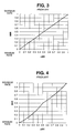
- linear mapping is easiest to implement, most mapping attempts so far tended to be straight line approximations, as illustrated in Figures 1-5. In Figures 1-5, both the vertical and the horizontal scales are normalized for ease of comparison.
- the minimum and maximum values of the metabolic rate interval are disposed at 0 and 1 respectfully along the vertical axis.
- cor-responding minimum and maximum values of the minute ventilation are disposed at 0 and 1 respectively along the horizontal axis.
- the same convention is used in Figures 2-5 except that in the latter Figures the vertical axis indicates a normalized Metabolic Indicated Rate (MIR) as opposed to an interval.
- MIR Metabolic Indicated Rate
- rate responsive systems making use of the minute ventilation as a parameter, first calculate a long term average for the minute ventilation of a patient and then determine the difference between this long term average and an instantaneous minute ventilation obtained as described below, in conjunction with Figures 7-11.
- the resulting differential parameter is referred to as "the minute ventilation" for the sake of brevity.
- the parameter is identified as ⁇ MV to indicate that, in fact, this parameter corresponds to the variation of the instantaneous minute ventilation from a long term average value.
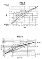
- augmented rate response factor shown in Figure 5
- line A is the rate response factor (RRF) similar to that of Figure 3.
- the rate response factor is a parameter selectable in some pacemakers by a physician based on his evaluation of the patient and his own experience.
- Profiles B, C and D in this Figure represent three dual slope profiles, each profile consisting of two line segments: an initial, or lower rate segment for the beginning of the exercise having a first slope, and a higher rate segment having a second slope.
- the physician is given the choice of selecting a low, medium or high initial RRF as the first slope. Each of these initial RRF values is higher than the base RRF.
- line segment B1 had a slope equal to a low initial RRF
- line segment C1 had a slope equal to a medium initial RRF
- line segment 01 had a slope equal to a high initial RRF.
- the maximum and minimum MIR rates were also left to the physician's discretion or choice based on his experience and physical evaluation of the patient.
- the second line segment for each profile, i.e., B2, C2, and D2 were then extended from the respective breakpoint B', C', and D' to the upper limit of the base line A, as shown. Even though improved, however, this approach still did not correspond to the actual relationship between the intrinsic heart rate and minute volume, especially at more moderate higher exercise levels. Details of this mapping are described in U.S. Patent. No. 5,292,390 incorporated herein by reference.
- mapping using a single RRF value as a slope is unsatisfactory because it ignores the need for a faster response during the initial or exercise level, and the need for a decreased response relative to minute ventilation at higher exercise levels.
- a mapping in which two line segments are used and the initial slope was set to a preselected RRF is still unsatisfactory because it relies on an artificial transition or break point between the line segments.
- a pacemaker which dynamically responds to the instantaneous physical level of activity of a patient and adjusts its pulse rate accordingly, based on a preselected parameter, namely, the ratio of two rate response factors, an initial, and a higher exercise level, rate response factor.
- a further objective is to provide a metabolic rate responsive pacemaker which generates pulses at the appropriate rate by following a profile which closely matches the profile of a healthy person, i.e., a person having no pacemaker, both below and above the patient's anaerobic threshold, discussed in more detail below.
- a pacemaker constructed in accordance with this invention includes sensing means for sensing a metabolic demand parameter of the patient highly correlated or coupled to his or her physical activity.
- the metabolic demand parameter is a minute ventilation, in physiologic terms, which can be determined, for example, from impedance measurements. Minute ventilation has been found to be an accurate representation of the oxygen demand of a patient.
- This parameter is converted into a corresponding metabolic indicated rate (MIR), whose rate may be used to define the interval between the pacer pulses.
- MIR metabolic indicated rate
- the mapping of minute volume to a metabolic indicated rate (MIR) preferably takes into consideration the estimated anaerobic threshold of the patient, his or her age.
- the metabolism of a person during exercise can be defined in terms of an aerobic and an anaerobic phase.
- the aerobic phase corresponds to a sustainable steady state, during which the pulmonary and cardiovascular system provides all the oxygen required by the metabolic demand.
- the oxygen demand cannot be met by the system.
- the person in the anaerobic phase, the person can maintain the level of exercise only until oxygen starvation sets in.
- the transition between these phases is the anaerobic threshold (AT). It has been found experimentally that the AT can be expressed as a heart rate level which is a percentage of the age predicted maximum heart rate of the patient.
- anaerobic threshold level is between the maximum and minimum heart rate of the patient, a profile formed by two line segments, and having a breakpoint at the anaerobic threshold level, is used for mapping minute volume with a metabolic indicated rate.
- the ideal solution would be to allow the physician to specify two different rate response 5 factors, each defining the slope of one of the segments.
- this approach is not practical because it may result in one of the segments being too long or too short.
- the present inventors have found that a well-defined, accurate mapping can be achieved if the physician is allowed to select, instead, the ratio of the rate factors, which corresponds to the ratio of the slopes of the line segments. Allowing the physician to choose the slope ratio provides the physician with a control over both the initial and high level rate response factors. Setting the break point, the heart rate value between the line segments at the AT level, insures that the proper rate response is used for the aerobic and anaerobic metabolic phases, respectively.
- the slope ratio is selected by the physician dependent on the age of the patient.
- the AT level is almost always about 70% of a person's age predicted maximum heart rate (HR), for which there are standard values, while the ratio of the slopes has been found to be related to the age of a person.
- This AT level was found to be relatively constant for a range of normal subjects with a standard deviation of 8%.
- FIG. 6 A mapping of the relationship of minute volume to MIR, in accordance with this invention, is shown in Figure 6 for persons of various ages having a selected maximum heart rate of 140 bpm and a normal minimum heart rate of 60 bpm.
- line E characterizes the base rate response factor (RRF) when the anaerobic threshold is not used and profiles F, G and H are used for patients who are of various ages, with 'H' being the youngest.
- the break points F', G', H' are all positioned at the AT level, which is determined as described above.
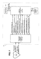
- FIG. 7 shows a block diagram of the pacemaker.
- the pacemaker 10 is designed to be implanted in a patient and is connected by leads 12 and 13 to a patient's heart 11 for sensing and pacing the heart 11 as described for example in co-pending application SN 226,654, filed April 12, 1994 by Tibor A. Nappholz et al., entitled FORCED ATRIOVENTRICULAR SYNCHRONY DUAL CHAMBER PACEMAKER, incorporated herein by reference.
- the atrial cardiac lead 12 extends into the atrium of the heart 11 and the ventricular cardiac lead 13 extends into the ventricle of the heart 11.
- Leads 12 and 13 are used for both sensing electrical activity in the heart and for applying pacing pulses to the heart.
- the pacemaker 10 includes a pace and sense circuit 17 for the detection of analog signals from leads 12 and 13 and for the delivery of pacing pulses to the heart; a microprocessor 19 which, in response to numerous inputs received from the pace and sense circuit 17, performs operations to generate different control and data outputs to the pace and sense circuit 17; and a power supply 18 which provides a voltage supply to the pace and sense circuit 17 and the microprocessor 19 by electrical conductors (not shown).
- the microprocessor 19 is connected to a random access memory/read only memory unit 121 by an address and data bus 122.
- a low power signal line 124 is used to provide to the microprocessor 19 a logic signal indicative of a low energy level of the power supply 18.
- the microprocessor 19 and the pace and sense circuit 17 are connected to each other by a number of data and control lines including a communication bus 42, an atrial sense line 45, an atrial pacing control line 46, an atrial sensitivity control bus 43, an atrial pace energy control bus 44, a ventricular sense line 49, a ventricular pace control line 50, a ventricular sensitivity control bus 47, and a ventricular pacing energy control bus 48.
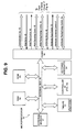
- FIG. 8 shows details of the pace and sense circuit 17.
- the circuit 17 includes an atrial pacing pulse generator 24, a ventricular pacing pulse generator 34, an atrial heartbeat sensor 25, a ventricular heartbeat sensor 35, and a telemetry circuit 30.
- the preferred embodiment of the pace and sense circuit 17 also includes an impedance measurement circuit 14 for measuring a physiological parameter indicative of the patient's metabolic demand.
- the pace and sense circuit 17 also includes a control block 39 which is interfaced to the microprocessor 19.
- the atrial and ventricular heartbeat sensor circuits 25 and 35 detect respective atrial and ventricular analog signals 23 and 33 from the heart 11 and convert the detected analog signals to digital signals.
- the heartbeat sensor circuits 25 and 35 receive an input atrial sense control signal on a control bus 27 and an input ventricular sense control signal on a control bus 37, respectively, from the control block 39. These control signals are used to set the sensitivity of the respective sensors.
- the atrial pacing pulse generator circuit 34 receives from the control block 39, via an atrial pacing control bus 28, an atrial pace control signal and an atrial pacing energy control signal to generate an atrial pacing pulse 22 at appropriate times.
- the ventricular pacing pulse generator circuit 34 receives from the control block 39, via a ventricular pacing control bus 38, a ventricular pace control signal and a ventricular pacing energy control signal to generate a ventricular pacing pulse 32.
- the atrial and ventricular pace control signal determine the respective timing of atrial and ventricular pacing that take place, while the atrial and ventricular pacing energy control inputs determine the respective magnitudes of the pulse energies.
- the pacemaker 10 performs an impedance measurement when the microprocessor 19 sends a signal on the impedance control bus 21 to activate the impedance measurement circuit 14.
- the impedance measurement circuit 14 then applies a current to the ventricular cardiac lead 13 via lead 20 and measures a voltage resulting from the applied current.
- These current and voltage signals define an impedance characteristic of the patient's metabolic demand, and more particularly, of the instantaneous minute volume. This instantaneous minute volume is then filtered and further modified by subtracting from it a long term average value, as discussed above. The resulting parameter is the minute volume parameter.
- the telemetry circuit 30 provides a bidirectional link between the control block 39 of the pace and sense circuit 17 and an external device such as a programmer. It allows data such as the operating parameters to be read from or altered in the implanted pacemaker.
- a programmer is the 9600 Network Programmer manufactured by Telectronics Pacing Systems, Inc. of Englewood, Colorado, U.S.A.
- Figure 9 shows the microprocessor 19 having a timer circuit 51 for generating several timing signals on its output ports A-E, a controller 53, an interrupt circuit 54, a ROM 55, a RAM 56, an external memory 57 and an interface port 41. Signals between these elements are exchanged via an internal communications bus 40. Timer circuits generate various timing signals at its output ports A-E.
- the RAM 56 acts as a scratchpad and active memory during execution of 5 the programs stored in the ROM 55 and used by the microprocessor 19.
- ROM 55 is used to store programs including system supervisory programs, detection algorithms for detecting and confirming arrhythmias, and programming for determining the rate of the pacer, as well as storage programs for storing, in external memory 57, data concerning the functioning of the pulse generator 10 and the electrogram provided by the ventricular cardiac lead 13.
- the timer circuit 51, and its associated control software, implements timing functions required by the microprocessor 19 without resorting entirely to software, thus reducing computational loads on, and power dissipation by, the controller 53.
- Signals received from the telemetry circuit 30 permit an external programmer (not shown) to change the operating parameters of the pace and sense circuit 17 by supplying appropriate signals to the control block 39.
- the communication bus 42 serves to provide signals indicative of such control to the microprocessor 19.
- the microprocessor 19 through its port 41 receives the status and/or control inputs from the pace and sense circuit 17, including the sense signals on the sense lines 45 and 49 previously described. Using controller 53, it performs various operations, including arrhythmia detection, and produces outputs, such as the atrial pace control on the line 46 and the ventricular pace control on the line 50, which determine the type of pacing that is to take place. Other control outputs generated by the microprocessor 19 include the atrial and ventricular pacing energy controls on the buses 44 and 48, respectively, which determine the magnitude of the pulse energy, and the atrial and ventricular sensitivity controls on the buses 43 and 47, respectively, which set the sensitivities of the sensing circuits. The rate of the atrial and/or ventricle pacing is adjusted by controller 53 as set forth below by making use of the anaerobic threshold.
- the pacemaker 10 of the present invention will function properly using any metabolic indicator rate system, so long as that system is able to reliably relate the sensed parameter to an appropriate matching of metabolic demand with the paced rate.
- the preferred embodiment of the invention employs the impedance measurement circuit 14, shown in Fig. 8, which measures the cardiac impedance to determine the respiratory minute volume as described in U. S. Patent No. 4,901,725 to T. A. Nappholz, et al., issued February 20, 1990 for "Minute Volume Rate-Responsive Pacemaker", incorporated herein by reference.
- FIG. 10 shows the block diagram of the controller 53 of Figure 9.
- the controller 53 includes a pacer 53C, a minute volume processor 53A and an atrial rate monitor 53B.
- the minute volume processor 53A uses the data supplied via the internal bus 40 and the communication bus 42 from the impedance measurement block 14 to relate the minute volume indicated by the impedance measurement to the Metabolic Indicated Rate (MIR). This rate is then used by the pacer 53C to determine the length of each interval in the timing cycle. While the pacemaker 10 is preferably operating in a DDD mode, it should be understood that it can operate in other modes as well.
- the atrial rate monitor 53B generates an Automatic Mode Switching (AMS) signal upon detection of a non-physiological atrial rate and rhythm. This AMS signal automatically switches the pacemaker 10 to a ventricular pacing mode, where atrial pacing is temporarily disabled. When a physiological atrial rate resumes, the AMS signal is deactivated and the pacemaker returns to an atrial tracking mode.
- AMS Automatic Mode Switching
- the minute volume processor 53A includes a minute volume determining circuit 70 and a converting circuit 72.
- Circuit 70 receives the impedance signal from impedance measurement circuit 14.
- the corresponding minute volume is determined by circuit 70 as described in detail in the above mentioned U.S. Patent No. 4,901,725, and is provided to the converting circuit 72.
- This converting circuit makes use of a mapping profile generated during the initialization of the pacemaker.
- converting circuit 72 is shown as a discrete element for the sake of clarity, this circuit 72 is preferably implemented by software performed, for example, by microprocessor 39.
- step 80 the physician sets various operational parameters when the patient is at rest. These parameters include the age of the patient, the maximum MIR rate, and the minimum MIR rate as well as the patient's physical fitness, or life style. Some of these parameters may be preset or calculated by the microprocessor to nominal values and the physician may be given the choice of accepting the nominal value or selecting another value. For example, the maximum MIR rate is normally calculated so that it is equal to 90% of a normal maximum heart rate (HR) based on age. The physician then may decide to accept this nominal value, or may select another value for this parameter. Similarly, the base line RRF may be set for a nominal value of 10. Again, the physician can accept this value, or may decide to set the baseline RRF to a different value.
- HR normal maximum heart rate
- the normal maximum heart rate is given by: This is a standard formula used to determine age predicted maximum HR.
- the nominal value for the maximum MIR is 90% of maximum HR or about 153 ppm.
- the maximum MIR rate may be set to 155 ppm, as shown in Figure 6.
- the physician may set the maximum MIR to a different value.
- the minimum MIR is normally set to 60 ppm.
- the present pacemaker has the capability of modifying the MIR mapping based on age and physical fitness, or lifestyle (called herein the Anaerobic Threshold Adapter, or ATA) as described, a physician may decide not to use this feature. Therefore, in step 82, he is given a choice of turning this feature off. If the ATA system is turned off, the mapping is performed in step 86, as described below.
- ATA Anaerobic Threshold Adapter
- step 84 the anaerobic threshold (AT) level is calculated.
- AT (HR) ⁇ 0.71
- step 88 a decision is made as to whether the AT level is in the range selected in step 80, i.e., whether (3) minimum MIR rate ⁇ AT ⁇ maximum MIR rate.
- step 86 is necessary because, while unlikely, it may be possible for the threshold level to fall outside the range of MIR, and the subject pacemaker would be unable to define the breakpoint between the line segments and a corresponding two-slope profile. Therefore, if the calculated AT level is below this range, or if the difference between Max rate and Min rate is less than 10 ppm then circuit 72 generates a straight mapping in step 86.
- This mapping is defined as the straight line profile E shown in Figure 6, having a slope equal to RRF (the baseline rate response factor selected or set in step 80). If the AT level is within range, the microprocessor cycles to step 90.
- step 90 a determination must be made whether the AT level is too close to the maximum MIR rate. If it is too close, for example, within 10 ppm, then the AT level is reset in step 92 to a new value dependent on the maximum MIR rate. For example, the new AT level may be set to be 10 ppm less than the maximum MIR rate.
- step 94 the slope ratio Sr is calculated.
- This expression represents an increase in Sr ATHLETIC of one standard deviation over the slope ratio of equation (4).
- step 94 the slope ratio for the patient is calculated using the above-defined formulas.
- the slope ratio may be retrieved from a look-up table.
- a typical look-up table derived from eleven age ranges is shown below, with the actual age used in the formulas being indicated in parentheses.
- the slope ratio Sr found in step 94 and the anaerobic threshold AT rate from step 90 or 92 are the two parameters which together define the specific dual slope profile (F, G or H) required for mapping by the present ATA system, as shown in Figure 6.
- the profile can be determined by generating the equations for the two line segments from the slope ratio Sr, and the threshold level AT, or by using a look-up table.
- a profile F is generated having two line segments F1 and F2 ( Figure 6).
- Similar profiles G and H can be defined for the average and the athletic patient, respectively.
- the determination circuit 70 periodically measures the minute volume parameter in response to the instantaneous metabolic demand of the patient.
- the mapping circuit 72 then converts this minute volume into a corresponding MIR using the mapping profile generated as set forth above. For example, for a sedentary 65 year old patient, for every minute volume reading below the AT level, a corresponding MIR is selected by mapping circuit 72 using line segment F1. Above the AT level, an MIR rate is selected using line segment F2. The MIR rate is then fed to the pacer 53C for controlling pacing pulses at the proper rate.
Landscapes
- Health & Medical Sciences (AREA)
- Cardiology (AREA)
- Heart & Thoracic Surgery (AREA)
- Life Sciences & Earth Sciences (AREA)
- Biophysics (AREA)
- Physiology (AREA)
- Engineering & Computer Science (AREA)
- Biomedical Technology (AREA)
- Nuclear Medicine, Radiotherapy & Molecular Imaging (AREA)
- Radiology & Medical Imaging (AREA)
- Animal Behavior & Ethology (AREA)
- General Health & Medical Sciences (AREA)
- Public Health (AREA)
- Veterinary Medicine (AREA)
- Hematology (AREA)
- Electrotherapy Devices (AREA)
Applications Claiming Priority (2)
| Application Number | Priority Date | Filing Date | Title |
|---|---|---|---|
| US405507 | 1995-03-16 | ||
| US08/405,507 US5487753A (en) | 1995-03-16 | 1995-03-16 | Rate-responsive pacemaker with anaerobic threshold adaptation and method |
Publications (3)
| Publication Number | Publication Date |
|---|---|
| EP0732123A2 true EP0732123A2 (fr) | 1996-09-18 |
| EP0732123A3 EP0732123A3 (fr) | 1997-03-19 |
| EP0732123B1 EP0732123B1 (fr) | 2002-12-11 |
Family
ID=23603985
Family Applications (1)
| Application Number | Title | Priority Date | Filing Date |
|---|---|---|---|
| EP96300100A Expired - Lifetime EP0732123B1 (fr) | 1995-03-16 | 1996-01-04 | Stimulateur cardiaque avec adaptation au seuil anaérobie |
Country Status (3)
| Country | Link |
|---|---|
| US (1) | US5487753A (fr) |
| EP (1) | EP0732123B1 (fr) |
| DE (1) | DE69625262T2 (fr) |
Families Citing this family (31)
| Publication number | Priority date | Publication date | Assignee | Title |
|---|---|---|---|---|
| EP0804938B1 (fr) * | 1996-04-29 | 2004-07-07 | Pacesetter, Inc. | Stimulateur cardiaque à détermination du seuil anaérobique |
| US5792198A (en) * | 1996-04-30 | 1998-08-11 | Nappholz; Tibor A. | Auto adaptation of RR interval in implantable pacemaker |
| US5792196A (en) * | 1996-04-30 | 1998-08-11 | Cooper; Daniel | Rate-responsive pacemaker with automatic rate response factor selection |
| US5690687A (en) * | 1996-08-22 | 1997-11-25 | Pacesetter, Inc. | Pacemaker with improved distributed rate pacing |
| US5800469A (en) * | 1997-04-16 | 1998-09-01 | Nappholz; Tibor A. | Pacemaker with anaerobic threshold determination |
| US5817135A (en) * | 1997-05-02 | 1998-10-06 | Pacesetter, Inc. | Rate-responsive pacemaker with noise-rejecting minute volume determination |
| US5817136A (en) * | 1997-05-02 | 1998-10-06 | Pacesetter, Inc. | Rate-responsive pacemaker with minute volume determination and EMI protection |
| US5836988A (en) * | 1997-05-02 | 1998-11-17 | Pacesetter, Inc. | Rate responsive pacemaker with exercise recovery using minute volume determination |
| US5824020A (en) * | 1997-05-02 | 1998-10-20 | Pacesetter, Inc. | Rate-responsive pacemaker with rapid minute volume determination |
| US6073089A (en) * | 1997-10-22 | 2000-06-06 | Baker; Michelle | Systems and methods for adaptive profiling, fault detection, and alert generation in a changing environment which is measurable by at least two different measures of state |
| DE19859653A1 (de) | 1998-12-15 | 2000-06-21 | Biotronik Mess & Therapieg | Selbstkalibrierender ratenadaptiver Herzschrittmacher |
| US6411850B1 (en) * | 1999-09-30 | 2002-06-25 | Uab Research Foundation | Method of determining a ventilatory threshold breakpoint for an adaptive rate pacemaker |
| US6490485B1 (en) * | 1999-10-06 | 2002-12-03 | Cardiac Pacemakers, Inc. | Automatic rate-adaptive pacing with auto-lifestyle |
| US6408208B1 (en) * | 1999-10-28 | 2002-06-18 | Cardiac Pacemakers, Inc. | Fully automatic and physiologic rate-adaptive pacing |
| US6519495B1 (en) * | 2000-08-15 | 2003-02-11 | Cardiac Pacemakers, Inc. | Rate-adaptive therapy with sensor cross-checking |
| US6839593B1 (en) | 2000-09-08 | 2005-01-04 | Cardiac Pacemakers, Inc. | Rate-adaptive therapy with automatic limiting of maximum pacing rate |
| US6823214B1 (en) | 2000-09-08 | 2004-11-23 | Cardiac Pacemakers, Inc. | Self-calibrating rate-adaptive pacemaker |
| US6741885B1 (en) | 2000-12-07 | 2004-05-25 | Pacesetter, Inc. | Implantable cardiac device for managing the progression of heart disease and method |
| US6484057B2 (en) | 2000-12-21 | 2002-11-19 | Uab Research Foundation | Pacing methods and devices for treating cardiac arrhythmias and fibrillation |
| US6990375B2 (en) * | 2001-03-02 | 2006-01-24 | Cardiac Pacemakers, Inc. | Adjustment of the breakpoint of the rate response curve based on minute ventilation values |
| TW555544B (en) * | 2001-05-28 | 2003-10-01 | Tonic Fitness Technology Inc | Method for measuring anaerobic threshold by detection and analysis of heartbeat data obtained during exercise |
| US7139608B2 (en) * | 2002-07-31 | 2006-11-21 | Uab Research Foundation | Pacing methods and devices using feedback controlled timing |
| US20040049118A1 (en) * | 2002-09-10 | 2004-03-11 | Ideker Raymond E. | Methods, systems and computer program products for treating fibrillation in a patient based on the presence of fibrillation following administration of defibrillation therapy |
| US8560063B2 (en) * | 2002-09-10 | 2013-10-15 | Uab Research Foundation | Post-defibrillation pacing methods and devices |
| US7162298B2 (en) * | 2002-09-10 | 2007-01-09 | Uab Research Foundation | Devices for detecting the presence of cardiac activity following administration of defibrillation therapy |
| US7207947B2 (en) * | 2003-01-10 | 2007-04-24 | Pacesetter, Inc. | System and method for detecting circadian states using an implantable medical device |
| US7522958B2 (en) * | 2003-03-13 | 2009-04-21 | Uab Research Foundation | Methods and systems for reducing discomfort from cardiac defibrillation shocks |
| US8013133B2 (en) | 2003-04-25 | 2011-09-06 | Medtronic, Inc. | Genetic modification of targeted regions of the cardiac conduction system |
| US7734344B2 (en) | 2003-12-02 | 2010-06-08 | Uab Research Foundation | Methods, systems and computer program products to inhibit ventricular fibrillation during cardiopulmonary resuscitation |
| US8936556B2 (en) * | 2008-09-24 | 2015-01-20 | Cardiac Pacemakers, Inc. | Minute ventilation-based disordered breathing detection |
| WO2010138388A1 (fr) * | 2009-05-26 | 2010-12-02 | Cardiac Pacemakers, Inc. | Normalisation et calcul de réponse de vitesse de détecteur de ventilation |
Citations (3)
| Publication number | Priority date | Publication date | Assignee | Title |
|---|---|---|---|---|
| FR2576205A3 (fr) * | 1985-01-23 | 1986-07-25 | Chanon Raymond | Test de terrain permettant d'evaluer chez les sportifs la consommation maximale d'oxygene (ou vo2 max.), les seuils anaerobie et aerobie, une courbe de recuperation cardiaque et un indice du niveau de forme |
| US5297558A (en) * | 1993-03-12 | 1994-03-29 | Medical Graphics Corporation | Algorithm for prescribing an exercise regimen to enhance fat burning and cardiovascular fitness |
| US5303702A (en) * | 1990-12-27 | 1994-04-19 | Ela Medical | Automatic adjustment of the control function for a rate adaptive pacemaker |
Family Cites Families (1)
| Publication number | Priority date | Publication date | Assignee | Title |
|---|---|---|---|---|
| US4901725A (en) * | 1988-01-29 | 1990-02-20 | Telectronics N.V. | Minute volume rate-responsive pacemaker |
-
1995
- 1995-03-16 US US08/405,507 patent/US5487753A/en not_active Expired - Lifetime
-
1996
- 1996-01-04 EP EP96300100A patent/EP0732123B1/fr not_active Expired - Lifetime
- 1996-01-04 DE DE69625262T patent/DE69625262T2/de not_active Expired - Fee Related
Patent Citations (3)
| Publication number | Priority date | Publication date | Assignee | Title |
|---|---|---|---|---|
| FR2576205A3 (fr) * | 1985-01-23 | 1986-07-25 | Chanon Raymond | Test de terrain permettant d'evaluer chez les sportifs la consommation maximale d'oxygene (ou vo2 max.), les seuils anaerobie et aerobie, une courbe de recuperation cardiaque et un indice du niveau de forme |
| US5303702A (en) * | 1990-12-27 | 1994-04-19 | Ela Medical | Automatic adjustment of the control function for a rate adaptive pacemaker |
| US5297558A (en) * | 1993-03-12 | 1994-03-29 | Medical Graphics Corporation | Algorithm for prescribing an exercise regimen to enhance fat burning and cardiovascular fitness |
Non-Patent Citations (1)
| Title |
|---|
| PACE, vol. 15, August 1992, C.-P. LAU "The Range of Sensors and Algorithms Used in Rate Adaptive Cardiac Pacing" pages 1177-1180 * |
Also Published As
| Publication number | Publication date |
|---|---|
| DE69625262T2 (de) | 2003-08-28 |
| EP0732123A3 (fr) | 1997-03-19 |
| US5487753A (en) | 1996-01-30 |
| EP0732123B1 (fr) | 2002-12-11 |
| DE69625262D1 (de) | 2003-01-23 |
Similar Documents
| Publication | Publication Date | Title |
|---|---|---|
| EP0732123B1 (fr) | Stimulateur cardiaque avec adaptation au seuil anaérobie | |
| US5626622A (en) | Dual sensor rate responsive pacemaker | |
| US5480413A (en) | Apparatus and method for stabilizing the ventricular rate of a heart during atrial fibrillation | |
| US5964788A (en) | Method and apparatus for controlling a pacemaker using respiration | |
| US5817136A (en) | Rate-responsive pacemaker with minute volume determination and EMI protection | |
| US5226413A (en) | Rate responsive pacemaker and method for automatically initializing the same | |
| US5549650A (en) | System and method for providing hemodynamically optimal pacing therapy | |
| US5643327A (en) | Pacemaker and method having optimized A-V delay by using the evoked depolarization potential as an indicia of cardiac output | |
| EP0615770B1 (fr) | Dispositif pour gérer et contrÔler le rythme cardiaque en utilisant comme paramètre de contrÔle la "période active" | |
| US5156147A (en) | Variable rate pacemaker having upper rate limit governor based on hemodynamic performance | |
| US5441523A (en) | Forced atrioventricular synchrony dual chamber pacemaker | |
| US4782836A (en) | Rate adaptive cardiac pacemaker responsive to patient activity and temperature | |
| US5487752A (en) | Automated programmable stimulating device to optimize pacing parameters and method | |
| US5312453A (en) | Rate responsive cardiac pacemaker and method for work-modulating pacing rate deceleration | |
| US5741308A (en) | Dual-chamber implantable pacemaker and method of operating same for automatically setting the pacemaker's AV interval as a function of a natural measured conduction time | |
| US4688573A (en) | Temperature driven rate responsive cardiac pacemaker | |
| EP0331309B1 (fr) | Stimulateur cardiaque sensible à la fréquence | |
| US4966146A (en) | Rate-responsive pacemaker | |
| US5161527A (en) | Apparatus and method for detecting abnormal cardiac rhythms in dual chamber arrhythmia control system | |
| US5891176A (en) | System and method for providing hemodynamically optimal pacing | |
| US6937900B1 (en) | AC/DC multi-axis accelerometer for determining patient activity and body position | |
| US6055454A (en) | Cardiac pacemaker with automatic response optimization of a physiologic sensor based on a second sensor | |
| US20020188329A1 (en) | Pressure-modulated rate-responsive cardiac pacing | |
| JPH06190065A (ja) | 心臓ペースメーカーおよび心臓ペースメーカーを作動する方法 | |
| US5836988A (en) | Rate responsive pacemaker with exercise recovery using minute volume determination |
Legal Events
| Date | Code | Title | Description |
|---|---|---|---|
| PUAI | Public reference made under article 153(3) epc to a published international application that has entered the european phase |
Free format text: ORIGINAL CODE: 0009012 |
|
| AK | Designated contracting states |
Kind code of ref document: A2 Designated state(s): DE FR GB |
|
| PUAL | Search report despatched |
Free format text: ORIGINAL CODE: 0009013 |
|
| AK | Designated contracting states |
Kind code of ref document: A3 Designated state(s): DE FR GB |
|
| 17P | Request for examination filed |
Effective date: 19970822 |
|
| 17Q | First examination report despatched |
Effective date: 20010820 |
|
| GRAG | Despatch of communication of intention to grant |
Free format text: ORIGINAL CODE: EPIDOS AGRA |
|
| RTI1 | Title (correction) |
Free format text: RATE-RESPONSIVE PACEMAKER WITH ANAEROBIC THRESHOLD ADAPTATION |
|
| RTI1 | Title (correction) |
Free format text: RATE-RESPONSIVE PACEMAKER WITH ANAEROBIC THRESHOLD ADAPTATION |
|
| GRAG | Despatch of communication of intention to grant |
Free format text: ORIGINAL CODE: EPIDOS AGRA |
|
| GRAH | Despatch of communication of intention to grant a patent |
Free format text: ORIGINAL CODE: EPIDOS IGRA |
|
| GRAH | Despatch of communication of intention to grant a patent |
Free format text: ORIGINAL CODE: EPIDOS IGRA |
|
| GRAA | (expected) grant |
Free format text: ORIGINAL CODE: 0009210 |
|
| AK | Designated contracting states |
Kind code of ref document: B1 Designated state(s): DE FR GB |
|
| REG | Reference to a national code |
Ref country code: GB Ref legal event code: FG4D |
|
| RAP2 | Party data changed (patent owner data changed or rights of a patent transferred) |
Owner name: PACESETTER, INC. |
|
| REF | Corresponds to: |
Ref document number: 69625262 Country of ref document: DE Date of ref document: 20030123 |
|
| PG25 | Lapsed in a contracting state [announced via postgrant information from national office to epo] |
Ref country code: GB Free format text: LAPSE BECAUSE OF NON-PAYMENT OF DUE FEES Effective date: 20030311 |
|
| ET | Fr: translation filed | ||
| PLBE | No opposition filed within time limit |
Free format text: ORIGINAL CODE: 0009261 |
|
| STAA | Information on the status of an ep patent application or granted ep patent |
Free format text: STATUS: NO OPPOSITION FILED WITHIN TIME LIMIT |
|
| GBPC | Gb: european patent ceased through non-payment of renewal fee |
Effective date: 20030311 |
|
| 26N | No opposition filed |
Effective date: 20030912 |
|
| PGFP | Annual fee paid to national office [announced via postgrant information from national office to epo] |
Ref country code: FR Payment date: 20060117 Year of fee payment: 11 |
|
| PGFP | Annual fee paid to national office [announced via postgrant information from national office to epo] |
Ref country code: DE Payment date: 20070228 Year of fee payment: 12 |
|
| REG | Reference to a national code |
Ref country code: FR Ref legal event code: ST Effective date: 20070930 |
|
| PG25 | Lapsed in a contracting state [announced via postgrant information from national office to epo] |
Ref country code: FR Free format text: LAPSE BECAUSE OF NON-PAYMENT OF DUE FEES Effective date: 20070131 |
|
| PG25 | Lapsed in a contracting state [announced via postgrant information from national office to epo] |
Ref country code: DE Free format text: LAPSE BECAUSE OF NON-PAYMENT OF DUE FEES Effective date: 20080801 |