EP0731609A2 - Procédé de quantification vectorielle sur réseau contrainte en débit - Google Patents
Procédé de quantification vectorielle sur réseau contrainte en débit Download PDFInfo
- Publication number
- EP0731609A2 EP0731609A2 EP96460007A EP96460007A EP0731609A2 EP 0731609 A2 EP0731609 A2 EP 0731609A2 EP 96460007 A EP96460007 A EP 96460007A EP 96460007 A EP96460007 A EP 96460007A EP 0731609 A2 EP0731609 A2 EP 0731609A2
- Authority
- EP
- European Patent Office
- Prior art keywords
- points
- point
- quantified
- quantized
- network
- Prior art date
- Legal status (The legal status is an assumption and is not a legal conclusion. Google has not performed a legal analysis and makes no representation as to the accuracy of the status listed.)
- Withdrawn
Links
Images


Classifications
-
- H—ELECTRICITY
- H03—ELECTRONIC CIRCUITRY
- H03M—CODING; DECODING; CODE CONVERSION IN GENERAL
- H03M7/00—Conversion of a code where information is represented by a given sequence or number of digits to a code where the same, similar or subset of information is represented by a different sequence or number of digits
- H03M7/30—Compression; Expansion; Suppression of unnecessary data, e.g. redundancy reduction
- H03M7/3082—Vector coding
-
- G—PHYSICS
- G06—COMPUTING OR CALCULATING; COUNTING
- G06T—IMAGE DATA PROCESSING OR GENERATION, IN GENERAL
- G06T9/00—Image coding
- G06T9/008—Vector quantisation
-
- H—ELECTRICITY
- H04—ELECTRIC COMMUNICATION TECHNIQUE
- H04N—PICTORIAL COMMUNICATION, e.g. TELEVISION
- H04N19/00—Methods or arrangements for coding, decoding, compressing or decompressing digital video signals
- H04N19/10—Methods or arrangements for coding, decoding, compressing or decompressing digital video signals using adaptive coding
- H04N19/102—Methods or arrangements for coding, decoding, compressing or decompressing digital video signals using adaptive coding characterised by the element, parameter or selection affected or controlled by the adaptive coding
- H04N19/124—Quantisation
- H04N19/126—Details of normalisation or weighting functions, e.g. normalisation matrices or variable uniform quantisers
-
- H—ELECTRICITY
- H04—ELECTRIC COMMUNICATION TECHNIQUE
- H04N—PICTORIAL COMMUNICATION, e.g. TELEVISION
- H04N19/00—Methods or arrangements for coding, decoding, compressing or decompressing digital video signals
- H04N19/10—Methods or arrangements for coding, decoding, compressing or decompressing digital video signals using adaptive coding
- H04N19/134—Methods or arrangements for coding, decoding, compressing or decompressing digital video signals using adaptive coding characterised by the element, parameter or criterion affecting or controlling the adaptive coding
- H04N19/146—Data rate or code amount at the encoder output
- H04N19/147—Data rate or code amount at the encoder output according to rate distortion criteria
-
- H—ELECTRICITY
- H04—ELECTRIC COMMUNICATION TECHNIQUE
- H04N—PICTORIAL COMMUNICATION, e.g. TELEVISION
- H04N19/00—Methods or arrangements for coding, decoding, compressing or decompressing digital video signals
- H04N19/10—Methods or arrangements for coding, decoding, compressing or decompressing digital video signals using adaptive coding
- H04N19/169—Methods or arrangements for coding, decoding, compressing or decompressing digital video signals using adaptive coding characterised by the coding unit, i.e. the structural portion or semantic portion of the video signal being the object or the subject of the adaptive coding
- H04N19/182—Methods or arrangements for coding, decoding, compressing or decompressing digital video signals using adaptive coding characterised by the coding unit, i.e. the structural portion or semantic portion of the video signal being the object or the subject of the adaptive coding the unit being a pixel
-
- H—ELECTRICITY
- H04—ELECTRIC COMMUNICATION TECHNIQUE
- H04N—PICTORIAL COMMUNICATION, e.g. TELEVISION
- H04N19/00—Methods or arrangements for coding, decoding, compressing or decompressing digital video signals
- H04N19/10—Methods or arrangements for coding, decoding, compressing or decompressing digital video signals using adaptive coding
- H04N19/189—Methods or arrangements for coding, decoding, compressing or decompressing digital video signals using adaptive coding characterised by the adaptation method, adaptation tool or adaptation type used for the adaptive coding
- H04N19/19—Methods or arrangements for coding, decoding, compressing or decompressing digital video signals using adaptive coding characterised by the adaptation method, adaptation tool or adaptation type used for the adaptive coding using optimisation based on Lagrange multipliers
-
- H—ELECTRICITY
- H04—ELECTRIC COMMUNICATION TECHNIQUE
- H04N—PICTORIAL COMMUNICATION, e.g. TELEVISION
- H04N19/00—Methods or arrangements for coding, decoding, compressing or decompressing digital video signals
- H04N19/10—Methods or arrangements for coding, decoding, compressing or decompressing digital video signals using adaptive coding
- H04N19/189—Methods or arrangements for coding, decoding, compressing or decompressing digital video signals using adaptive coding characterised by the adaptation method, adaptation tool or adaptation type used for the adaptive coding
- H04N19/192—Methods or arrangements for coding, decoding, compressing or decompressing digital video signals using adaptive coding characterised by the adaptation method, adaptation tool or adaptation type used for the adaptive coding the adaptation method, adaptation tool or adaptation type being iterative or recursive
-
- H—ELECTRICITY
- H04—ELECTRIC COMMUNICATION TECHNIQUE
- H04N—PICTORIAL COMMUNICATION, e.g. TELEVISION
- H04N19/00—Methods or arrangements for coding, decoding, compressing or decompressing digital video signals
- H04N19/60—Methods or arrangements for coding, decoding, compressing or decompressing digital video signals using transform coding
- H04N19/63—Methods or arrangements for coding, decoding, compressing or decompressing digital video signals using transform coding using sub-band based transform, e.g. wavelets
-
- H—ELECTRICITY
- H04—ELECTRIC COMMUNICATION TECHNIQUE
- H04N—PICTORIAL COMMUNICATION, e.g. TELEVISION
- H04N19/00—Methods or arrangements for coding, decoding, compressing or decompressing digital video signals
- H04N19/90—Methods or arrangements for coding, decoding, compressing or decompressing digital video signals using coding techniques not provided for in groups H04N19/10-H04N19/85, e.g. fractals
- H04N19/94—Vector quantisation
-
- H—ELECTRICITY
- H04—ELECTRIC COMMUNICATION TECHNIQUE
- H04N—PICTORIAL COMMUNICATION, e.g. TELEVISION
- H04N19/00—Methods or arrangements for coding, decoding, compressing or decompressing digital video signals
- H04N19/10—Methods or arrangements for coding, decoding, compressing or decompressing digital video signals using adaptive coding
- H04N19/102—Methods or arrangements for coding, decoding, compressing or decompressing digital video signals using adaptive coding characterised by the element, parameter or selection affected or controlled by the adaptive coding
- H04N19/115—Selection of the code volume for a coding unit prior to coding
-
- H—ELECTRICITY
- H04—ELECTRIC COMMUNICATION TECHNIQUE
- H04N—PICTORIAL COMMUNICATION, e.g. TELEVISION
- H04N19/00—Methods or arrangements for coding, decoding, compressing or decompressing digital video signals
- H04N19/10—Methods or arrangements for coding, decoding, compressing or decompressing digital video signals using adaptive coding
- H04N19/134—Methods or arrangements for coding, decoding, compressing or decompressing digital video signals using adaptive coding characterised by the element, parameter or criterion affecting or controlling the adaptive coding
- H04N19/146—Data rate or code amount at the encoder output
Definitions
- the present invention relates to a vector quantization method on a rate constrained network.
- the vector quantization technique on a network is well known and is used in particular in video or audio signal compression systems.
- the method of the invention can find application in all the fields where the quantization function is essential, the present description envisages only the case of quantization of image signals. It will be noted that in this particular field, the method of the invention can be applied both for the coding and the transmission of conventional television signals and of high definition television signals as for applications at very low bit rates including coding techniques. will soon be the subject of standardization work.
- the image signals are broken down into a certain number of image sub-signals, such as sub-bands and the quantification method according to the invention applies to the signals from each of the sub-images.
- image sub-signals such as sub-bands
- quantification method according to the invention applies to the signals from each of the sub-images.
- sub-signal and sub-band are confused in favor of the term “sub-band”, but it will be understood that the invention applies in general to decomposed signals in sub-signals, whatever the process leading to this decomposition.
- the method of the invention can be used both for the coding of so-called signals, in the technical field, " intra signals " and for the coding of signals called "prediction error signals". In the latter case, this use is independent of the technique used for calculating the prediction signal, for example calculation based on conventional motion estimation and compensation algorithms, of the "block matching" or “quadtree” constrained type. throughput, or based on more sophisticated algorithms based on regional segmentation.
- Lattice vector quantization is the multidimensional extension of uniform scalar quantization. The latter consists in quantifying each pixel of an image separately in 2 N levels where N is the number of bits allocated to the quantizer. The quantization step q is chosen to be uniform.
- the quantification essentially consists in bringing all the values respectively taken, for each pixel, by the image signals in the sub-bands composing them in the interval [0, 2 N - 1], this by linear transformation of the form ax + b where a and b are calculated as a function of the number N of bits per pixel allocated to the quantizer and of the maximum and minimum values that these values can take in the sub-bands, and to reduce the values obtained by said transformation to the most integers close to the interval [0, 2 N - 1].
- Vector quantization on a network is associated with a regular network and makes it possible to quantify at a point of said network in a space of dimension n a vector whose components are the values taken by the image signals in a given sub-band for a grouping. of n pixels given. Each pixel vector is associated with a point in space which will be called the point to be quantified below. To do this, we determine the volume in which the vectors are located and then we bring back by a scale factor, or quantifier, applied to each group of pixels, all of the vectors of each sub-band in a volume containing roughly 2 nR points on the network where R is the desired bit rate. Finally, for each vector of a sub-band, the nearest point of the network is determined, by means of an algorithm, for all the vectors of each sub-band. From the coordinates of the network point thus determined, coding is carried out.
- the quantization of a vector generates a distortion which results from the distance between the point to be quantified and the point of the network.
- This distance can be formalized by a mathematical function such as the mean square error.
- the distortion is represented by the distance which separates the point to be quantified from the point of the network.
- the optimal quantization network for each signal to be quantified is determined, that is to say the network providing the minimum overall distortion given a total throughput Rd.
- This minimization is performed on a set of N quantizers distinguished from each other by different scale factors applied to the signals to be quantified.
- the distortion and the corresponding bit rate are calculated for each vector and for each quantizer in order to obtain, in a bit rate-distortion plane, a point cloud.
- the distortion values are for example calculated using the quantization algorithm described by J.H. Conway and N.J.A. Sloane in an article titled “Fast Quantizing and Decoding Algorithms for Lattice Quantizers and Codes” and published in IEEE trans. on Information Theory, 28 (2), March 1992.
- the throughput values are obtained using an entropy coding procedure of the "Huffman coding" type. It will be noted that the number of quantifiers determines the number of volumes into which the vectors to be quantified are projected as well as the fineness of the pitch between neighboring rates.
- a search is carried out on the envelope alone to obtain the point closest to the desired flow Rd. This point is the one which provides the smallest distortion with a flow less than or equal to the desired flow.
- the main idea of this process is based on the search for optimal quantifiers making it possible to obtain the lowest possible distortion for a given bit rate.
- the object of the invention is to further improve the method which has just been described and therefore to propose a vector quantization method on a network which makes it possible to reduce the overall distortion of the coded signals for a given bit rate.
- the idea which is the basis of the invention is the observation that the quantification carried out in known approaches does not take into account the cost of coding one vector with respect to another.
- a code must be transmitted for each vector.
- the vector probability densities follow Gaussian laws or generalized Gaussian laws. These laws are characterized by a strong probability at the origin and strongly decreasing thereafter. It is then preferable to code a vector by separating the code into two parts and making a polar representation of the vector.
- the vector is coded using a product code formed by a code for the standard and a code for the phase. These codes are assigned by entropy codings carried out according to, for example, the Huffman algorithm ".
- the densities of points on the adjacent isobod which result from the projection of the vectors on the points of the network do not vary in a uniform way with the norm.
- One calls an isonorme, a surface which is generated by the points of the network which have same standard.
- the denser the sound insulation the greater the average length of the phase code.
- the code assigned to the point on the network closest to the point to be quantified may be longer than that which would be assigned to another point on the more distant network.
- the cost of coding the first vector is said to be higher than that of the second.
- the object of the invention is therefore to provide a vector quantization method on a network which makes it possible to reduce the overall distortion of the coded signals for a given bit rate and which, moreover, takes into account not only the distortion but also the cost of coding the quantized vectors.
- a method according to the invention is of the type which consists in associating with a set of points representative of quantities characteristic of a signal to be quantified a set of points in a network, called points quantified, the polar coordinates of each of said quantized points being associated with a code.
- the invention consists in determining, among the points of the network located in a predetermined neighborhood of each quantized point, that which provides the best compromise expressed in a predetermined relationship between the distortion d resulting from the quantization of said point quantized and the bit rate r determined from the length of said code assigned to said quantized point, and to retain, as quantized points for coding, those which correspond to said determined points.
- said signal to be quantified is subdivided into a plurality of sub-signals.
- a differentiation of the distortion d assigned to each quantized point is carried out, depending on whether the point is representative of a sub-signal or another sub-signal.
- FIG. 1 therefore illustrates a quantification method according to the invention.
- the first loop 10 relates to the sub-bands SB of index i and to the number of M
- the second loop 20 relates to the quantifiers Q of index j and to the number of N.
- the point of the quantization network defined by a quantizer Q j which is sought for each point of the image to be quantified in the sub-band SB i is the closest to the vector associated with this point and this sub-band SB i .
- the quantification carried out here is a vector quantization applying to all types of networks.
- These networks can be, for example, a network of the type A n , (A 2 , A 3 , ...), a network of the type D n (D 4 , D 8 , ...), of the type E n , (E 4 , E 8 , ...) or of the type ⁇ n ( ⁇ 16 , ).
- a network of the type A n , (A 2 , A 3 , ...) a network of the type D n (D 4 , D 8 , ...), of the type E n , (E 4 , E 8 , ...) or of the type ⁇ n ( ⁇ 16 , ).
- a second step 40 for the vector associated with each point of the network determined in the first step 30, the distortion d generated by the approximation resulting from the quantization and the bit rate r resulting from the coding of the coordinates of the point of the network are calculated. previously determined.
- the distortion d for each point and for each subband SB i is calculated by considering the distance defined here as the mean or weighted quadratic error which separates the determined quantized point from the point to be quantified.
- the coding of the quantized point is carried out according to a polar representation, that is to say according to a product code formed by a standard code and a phase code.
- the standard and phase codes are entropy codes, such as "Huffman" codes.
- the standard used can be of the L 1 or L 2 type , the isonorms then being respectively hyperpyramids or hyperspheres.
- the flow r is deduced from the length of the codes respectively assigned to the quantified points.
- a table is given giving the characteristics of 90 vectors which, after quantification on a network D 4 of standard L 2 follow a given statistical distribution (see frequency line).
- the code lengths expressed in bits and allocated for the standard code, were obtained from a Huffman algorithm on the 10 different events.
- the fourth line gives the length of the standard code.
- the fifth line gives the number of vectors belonging to the isonorm and the sixth line gives the average length of the corresponding phase code.
- the latter is the length of a Huffman code produced by assuming the equiprobability of events on an isonorme of the network.
- a coordinate vector (0.6; -1.1; 1.7; 0.1) is quantified by the vector (1; -1; 2; 0).
- the norm L 2 of this vector is equal to 6.
- the coding of its standard is on 3 bits while that of its phase is on an average length of 6.66 bits.
- a product code of average length equal to 9.66 bits is therefore used.
- a third step 50 is calculated, always for the quantizer Q j and the subband SB i, D ij global distortion which is equal to the sum of the distortions d k on k points of the subband SB i considered as well as the overall bit rate R ij which results from the coding of all the k points of the sub-band SB i considered and which is therefore equal to the sum of the bit rates r k on all the points of the sub-band.
- Each pair (D ij , R ij ) obtained in step 50 can be represented by a point in a graph whose ordinate represents the global distortion D ij for the quantizer Q j in the subband SB i and the abscissa the global bit rate R ij for the same quantizer Q j in the same sub-band SB i .
- Such graphs have been shown in Figs. 3a, 3b and 3c for the sub-bands SB 1 , SB 2 and SB M.
- step 60 we seek, for the subband SB i , the convex envelope of the point cloud of the graph giving the global distortion D ij as a function of the global bit rate R ij (Figs. 3a to 3b). It is obtained point by point by searching, among all the lines of given slope 1 which pass respectively through the points of the cloud, that which has the weakest intercept and then by considering the point of the cloud through which passes this right.
- This operation is repeated for a given set of slope values ⁇ .
- the preceding steps 30 to 60 are repeated for all of the sub-bands SB 1 to SB M.
- the optimal points are poached in Figs. 3a to 3c.
- the set of couples (Dg, Rg) is represented in a graph in Fig. 4 for the set of values ⁇ 1 .
- step 80 the point of the curve (Dg, Rg) obtained in the previous step 70 is sought, the flow of which is lower than the flow Rc known as the target flow and which is the closest.
- the optimal point C therefore belongs to the line of the following equation: Dg + ⁇ opt Rg where ⁇ opt is determined in the previous step.
- This point C associated with the slope ⁇ opt makes it possible to establish the optimal combination of quantizers Q ij of the different sub-bands SB i , and thus to establish the quantized vectors of the quantization network.
- the coordinates of these vectors in the quantization network will give the quantization values.
- these coordinates are polar coordinates which are formed of a first value which is the norm of the vector considered and of a second value which is the phase of the same vector.
- the present invention is based on the observation that the cost of coding a vector is not identical for neighboring sound levels of the network.
- a vector of standard 16 in a network D 4 of standard L 2 is coded with fewer bits than a vector of standard 12 or of standard 20. If we refer to FIG. 2, it can be seen that a vector of norm 16 is coded on average on 8.66 bits while a vector of norm 12 is coded on average on 9.66 bits or of norm 20 on 12.22 bits.
- This observation stems from the fact that certain spheres of a network D 4 of standard L 2 are denser than others, which results in an average length of code for a vector, in particular for the phase, which is greater.
- the invention takes advantage of this observation to improve, for a desired bit rate Rd, the overall distortion Dg which results from the quantization.
- the invention consists in searching, in step 90, for each of the quantified points and, among its neighbors in a predetermined area, the point which provides the best compromise, i.e. the point which minimizes the following objective function: d + ⁇ opt r where d and r are respectively the distortion and the bit rate associated with the vector considered.
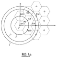
- step 80 we have considered, in FIG. 5a, a point V with coordinates (1, 0.9).
- a quantification on a network A 2 of standard L 2 It has been assumed that the quantification process described above gives point 1 (V3, 1) as the optimal quantification vector.
- Points A, B, C, D, E, and F are the immediate neighbors of point 1 in network A 2 .
- step 90 is therefore a set of quantized vectors which differs from the set of quantified vectors found previously.
- the overall distortion Dg the sum of the distortions affecting the quantized vectors, is greater, but the overall rate Rg has decreased.
- FIG. 6 There is shown in FIG. 6 a graph showing the signal to noise ratio as a function of the overall flow Rg.
- the signal-to-noise quantity is a function of the inverse of the Dg distortion.
- the target flow Rc is incremented in step 110 by a certain amount ⁇ r.
- the new target flow Rc becomes Rc '.
- a third loop 120 is therefore put in place.
- the points which decrease the objective function d + ⁇ opt r are then determined in step 90, then the global bit rate Rg and the global distortion Dg are calculated. On the graph of Fig. 6, the point Bo is then obtained.
- the implementation of the method of the invention provides, compared to an implementation of a conventional method, a gain of approximately 0.5 dB for the same flow Rd.
- the method of the invention is interrupted in step 100 when, after re-evaluation of the quantified vectors carried out in step 70, the flow rate obtained is close to the desired flow rate Rd, that is to say less than or equal to Rd.
- the search for vectors in step 60 now consists in minimizing the following objective function:
- W i is a term calculated according to psychovisual criteria.
- the assignment of psychovisual weights simply modifies the distortion measurements D ij , D g and d according to the sub-bands SB i . It will always be based on the quadratic error but multiplied by a term W i which will generally decrease as the sub-bands SB i represent the high frequencies.
Landscapes
- Engineering & Computer Science (AREA)
- Multimedia (AREA)
- Signal Processing (AREA)
- Theoretical Computer Science (AREA)
- Physics & Mathematics (AREA)
- General Physics & Mathematics (AREA)
- Compression, Expansion, Code Conversion, And Decoders (AREA)
Applications Claiming Priority (2)
| Application Number | Priority Date | Filing Date | Title |
|---|---|---|---|
| FR9501688 | 1995-02-09 | ||
| FR9501688A FR2730594B1 (fr) | 1995-02-09 | 1995-02-09 | Procede de quantification vectorielle sur reseau contrainte en debit |
Publications (2)
| Publication Number | Publication Date |
|---|---|
| EP0731609A2 true EP0731609A2 (fr) | 1996-09-11 |
| EP0731609A3 EP0731609A3 (enExample) | 1996-09-25 |
Family
ID=9476127
Family Applications (1)
| Application Number | Title | Priority Date | Filing Date |
|---|---|---|---|
| EP96460007A Withdrawn EP0731609A2 (fr) | 1995-02-09 | 1996-02-06 | Procédé de quantification vectorielle sur réseau contrainte en débit |
Country Status (2)
| Country | Link |
|---|---|
| EP (1) | EP0731609A2 (enExample) |
| FR (1) | FR2730594B1 (enExample) |
Families Citing this family (2)
| Publication number | Priority date | Publication date | Assignee | Title |
|---|---|---|---|---|
| EP0899960A3 (en) | 1997-08-29 | 1999-06-09 | Canon Kabushiki Kaisha | Digital signal coding and decoding |
| FR2767988A1 (fr) * | 1997-08-29 | 1999-03-05 | Canon Kk | Codage et decodage de signal numerique avec allocation adaptative de debit |
Family Cites Families (4)
| Publication number | Priority date | Publication date | Assignee | Title |
|---|---|---|---|---|
| FR2650926B1 (fr) * | 1989-08-08 | 1991-10-11 | Philips Electronique Lab | Procede et dispositif de quantification vectorielle de donnees numeriques |
| US5040217A (en) * | 1989-10-18 | 1991-08-13 | At&T Bell Laboratories | Perceptual coding of audio signals |
| DE69230268T2 (de) * | 1991-02-21 | 2000-04-13 | Nec Corp., Tokio/Tokyo | Kodierungsgerät zur Kompression von bewegten Bilddaten |
| EP0505654A1 (en) * | 1991-03-29 | 1992-09-30 | International Business Machines Corporation | Vector quantizing method for coding signals and system for implementing said method |
-
1995
- 1995-02-09 FR FR9501688A patent/FR2730594B1/fr not_active Expired - Fee Related
-
1996
- 1996-02-06 EP EP96460007A patent/EP0731609A2/fr not_active Withdrawn
Also Published As
| Publication number | Publication date |
|---|---|
| FR2730594A1 (fr) | 1996-08-14 |
| FR2730594B1 (fr) | 1997-03-21 |
| EP0731609A3 (enExample) | 1996-09-25 |
Similar Documents
| Publication | Publication Date | Title |
|---|---|---|
| EP0248711B1 (fr) | Procédé de codage par transformation pour la transmission de signaux d'image | |
| EP0628232B1 (en) | Fractal coding of data | |
| EP0294357B1 (fr) | Procédé de codage de signaux d'image | |
| EP0247075B1 (fr) | Procede de codage hybride par transformation pour la transmission de signaux d'image | |
| US6359928B1 (en) | System and method for compressing images using multi-threshold wavelet coding | |
| US5640159A (en) | Quantization method for image data compression employing context modeling algorithm | |
| EP0189703B1 (fr) | Procédé adaptatif de codage et de décodage d'une suite d'images par transformation, et dispositifs pour la mise en oeuvre de ce procédé | |
| US5414527A (en) | Image encoding apparatus sensitive to tone variations | |
| US6408026B1 (en) | Deadzone quantization method and apparatus for image compression | |
| FR2754127A1 (fr) | Procede de codage/decodage de signal video sur la base d'une quantification de treillis adaptative | |
| EP0668004B1 (fr) | Procede et dispositif de reduction de debit pour l'enregistrement d'images sur magnetoscope | |
| CA2346342C (fr) | Compression et codage de reseau maille tridimensionnel | |
| JPH0556282A (ja) | 画像符号化装置 | |
| US5629737A (en) | Method and apparatus for subband coding video signals | |
| EP0332553B1 (fr) | Procédé de réallocation de choix de traitement de sous-échantillonnage, sur critère de réduction de débit d'une séquence de données d'assistance à la reconstitution d'une image électronique sous-échantillonnée | |
| EP0731609A2 (fr) | Procédé de quantification vectorielle sur réseau contrainte en débit | |
| EP1574068B1 (fr) | Procede de codage d'une image par ondelettes et procede de decodage correspondant | |
| WO2007107659A2 (fr) | Quantification vectorielle contrainte | |
| Goeddel et al. | A two-dimensional quantizer for coding of digital imagery | |
| FR2597282A1 (fr) | Procede de quantification dans un codage par transformation pour la transmission de signaux d'image | |
| EP0762658B1 (fr) | Procédé de codage de données numériques représentées par des vecteurs et procédé de décodage des données codées selon ledit procédé de codage | |
| FR2878396A1 (fr) | Procede de codage d'images codees par ondelettes a controle du debit, dispositif de codage et programme d'ordinateur corespondants | |
| EP0524871B1 (fr) | Un procédé de codage de signaux hybride adaptatif | |
| Breaux et al. | Wavelet methods for compression, rendering, and descreening in digital halftoning | |
| WO1993002527A1 (fr) | Procede de regulation statistique de debit pour la transmission d'images numeriques |
Legal Events
| Date | Code | Title | Description |
|---|---|---|---|
| PUAI | Public reference made under article 153(3) epc to a published international application that has entered the european phase |
Free format text: ORIGINAL CODE: 0009012 |
|
| PUAL | Search report despatched |
Free format text: ORIGINAL CODE: 0009013 |
|
| AK | Designated contracting states |
Kind code of ref document: A2 Designated state(s): DE GB IT |
|
| RHK1 | Main classification (correction) |
Ipc: H03M 7/30 |
|
| AK | Designated contracting states |
Kind code of ref document: A3 Designated state(s): DE GB IT |
|
| 17P | Request for examination filed |
Effective date: 19961014 |
|
| 17Q | First examination report despatched |
Effective date: 19990712 |
|
| STAA | Information on the status of an ep patent application or granted ep patent |
Free format text: STATUS: THE APPLICATION IS DEEMED TO BE WITHDRAWN |
|
| 18D | Application deemed to be withdrawn |
Effective date: 19991123 |