EP0730965A2 - Translational wiping technique for an inkjet printhead - Google Patents
Translational wiping technique for an inkjet printhead Download PDFInfo
- Publication number
- EP0730965A2 EP0730965A2 EP96301527A EP96301527A EP0730965A2 EP 0730965 A2 EP0730965 A2 EP 0730965A2 EP 96301527 A EP96301527 A EP 96301527A EP 96301527 A EP96301527 A EP 96301527A EP 0730965 A2 EP0730965 A2 EP 0730965A2
- Authority
- EP
- European Patent Office
- Prior art keywords
- printhead
- ink
- wiping
- wiper
- service station
- Prior art date
- Legal status (The legal status is an assumption and is not a legal conclusion. Google has not performed a legal analysis and makes no representation as to the accuracy of the status listed.)
- Granted
Links
- 238000000034 method Methods 0.000 title claims description 8
- 239000007788 liquid Substances 0.000 claims description 4
- 230000008859 change Effects 0.000 abstract description 2
- 239000000976 ink Substances 0.000 description 48
- 238000007639 printing Methods 0.000 description 11
- 125000006850 spacer group Chemical group 0.000 description 4
- 230000009471 action Effects 0.000 description 3
- 238000004140 cleaning Methods 0.000 description 3
- 238000010304 firing Methods 0.000 description 3
- 230000037452 priming Effects 0.000 description 3
- 238000007790 scraping Methods 0.000 description 3
- 238000003491 array Methods 0.000 description 2
- 238000010586 diagram Methods 0.000 description 2
- 230000000694 effects Effects 0.000 description 2
- 238000007648 laser printing Methods 0.000 description 2
- 230000007246 mechanism Effects 0.000 description 2
- 230000004048 modification Effects 0.000 description 2
- 238000012986 modification Methods 0.000 description 2
- 239000000049 pigment Substances 0.000 description 2
- 229920002943 EPDM rubber Polymers 0.000 description 1
- 238000009825 accumulation Methods 0.000 description 1
- 239000000356 contaminant Substances 0.000 description 1
- 230000002089 crippling effect Effects 0.000 description 1
- 230000000881 depressing effect Effects 0.000 description 1
- 238000001035 drying Methods 0.000 description 1
- 239000001041 dye based ink Substances 0.000 description 1
- 229920001971 elastomer Polymers 0.000 description 1
- 239000000806 elastomer Substances 0.000 description 1
- 210000003128 head Anatomy 0.000 description 1
- 238000007641 inkjet printing Methods 0.000 description 1
- 238000009434 installation Methods 0.000 description 1
- 230000001050 lubricating effect Effects 0.000 description 1
- 239000000463 material Substances 0.000 description 1
- 239000001042 pigment based ink Substances 0.000 description 1
- 210000004894 snout Anatomy 0.000 description 1
Images


Classifications
-
- B—PERFORMING OPERATIONS; TRANSPORTING
- B41—PRINTING; LINING MACHINES; TYPEWRITERS; STAMPS
- B41J—TYPEWRITERS; SELECTIVE PRINTING MECHANISMS, i.e. MECHANISMS PRINTING OTHERWISE THAN FROM A FORME; CORRECTION OF TYPOGRAPHICAL ERRORS
- B41J2/00—Typewriters or selective printing mechanisms characterised by the printing or marking process for which they are designed
- B41J2/005—Typewriters or selective printing mechanisms characterised by the printing or marking process for which they are designed characterised by bringing liquid or particles selectively into contact with a printing material
- B41J2/01—Ink jet
- B41J2/135—Nozzles
- B41J2/165—Prevention or detection of nozzle clogging, e.g. cleaning, capping or moistening for nozzles
- B41J2/16517—Cleaning of print head nozzles
- B41J2/16535—Cleaning of print head nozzles using wiping constructions
- B41J2/16544—Constructions for the positioning of wipers
Definitions
- This application relates generally to inkjet printing, and more particularly to online service station functions of spitting ink into a spittoon, wiping ink orifices, capping an array of nozzles on a printhead, and priming inkjet cartridges,
- An inkjet printer has a printhead mounted in a carriage which periodically moves along a printhead path in a carriage scan direction to a stop position in a service station where an actuation device imparts translational motion to a wiper blade.
- the wiper blade moves along a linear wiping path orthogonal to the printhead path and across ink orifices on a nozzle surface of the printhead during a wiping operation.
- the wiper blade is removably mounted on a base and is split to form a first blade for wiping one column of ink orifices and a second blade for simultaneously wiping another column of ink orifices on a nozzle surface of the printhead.
- the service station provides different sequential wiping steps with successive wiper blades by first drawing ink onto the nozzle surface from the ink orifices with a rounded blade edge of a leading wiper blade, and then wiping the ink from the nozzle surface with a sharp blade edge of a following wiper blade.
- the sequential wiping steps are repeated twice during a normal wiping cycle -- once when the wiper blades leave a parking location to wipe across the stationary printhead, and again when the wiper blades change direction to wipe back across the same stationary printhead to return to the parking location located away from the printhead path.
- a 600 dpi 1/2 inch swath black pen with three 300 dpi color pens each generating a swath of approximately 1/3 inch.
- the high performance black pen has pigment based ink and is typically used for printing text and other "black only" features, and thus the output quality and throughput of these features is greater. It also improves the output quality of color graphics and color features by teaming with the three lower resolution color pens which have dye based inks for printing color graphics or color features.
- the black component of the graphics is often a large portion of color graphics content is at a higher resolution and thus at a higher cutout quality level. The larger swath of the black pen can thus be combined with printing algorithms to improve the throughput of color graphics.
- inkjet printer 10 includes an input tray 12 containing sheets of media 14 which pass through a print zone, and are fed past an exit 18 into an output tray 16.
- a movable carriage 20 holds print cartridges 22, 24, 26, and 28 which respectively old yellow (Y), magenta (M), cyan (C) and black (K) inks.
- the front of the carriage has a support bumper 30 which rides along a guide 32 while the back of the carriage has multiple bushings such as 34 which ride along slide rod 36.
- the position of the carriage as it traverses back and forth across the media is determined from an encoder strip 38 in order to be sure that the various ink nozzles on each print cartridge are selectively fired at the appropriate time during a carriage scan.
- the invention is applicable to printers wherein cartridge printheads are completely or partially staggered relative to each other in the direction of the media advance axis in order to provide better throughput, avoid color bleed, etc. or may be in direct alignment to provide overlapping swaths during a single pass of the carriage over a print zone.
- the invention provides a unique way for selectively servicing only certain individual cartridges during a given time period, or for performing some service activities at one station and other service activities at another, or for performing all services at the same time in the same station, regardless of the staggered or aligned relationship of the printheads, and all without removing the printhead cartridges from a print carriage, as described in more detail below.
- ink printheads While not limited to ink printheads have a particular type, size, resolution or configuration, the illustrated embodiment of the invention is used with ink cartridges having a dcuble column of ink orifices which extend in the media advance axis of the printer (see Fig. 15).
- wiping of the three color printheads is accomplished in a conventional manner by stationary wipers having a narrow blade portion with a top edge for rubbing across the nozzle plate as the print cartridge moves past the wipers.
- Scraping the stationary wipers is also accomplished in a conventional manner by using a snout edge of the moving printhead.
- Capping of the three color ink printheads (as well as for the black ink printhead) is accomplished in a conventional manner by a capper having four sets of perimeter lips for completely surrounding the orifice pattern without overlapping any outer edge of the nozzle plate. Priming of the three color ink printheads (as well as for the black ink printhead) is acccmplished in a conventional manner by a vacuum primer.
- the service station functioncns of the present invention are generally divided between a first service station 50 which is immediately on the right of a print zone 51 and a second service station 52 which is on the right of the first service station.
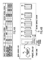
- the service functions of each are set fort in tabular form in Fig. 4A, and shown schematically in Fig. 4B.
- the direction of the translational back-and-forth wiping of the 600 dpi pigment based black ink printhead is identified by arrow 54 which is orthogonal to the carriage scan axis.
- a home location 56 for parking wiper blade member 688 during an actual printing operation is located away from printhead path 58, to avoid interference with any of the printheads which extend into the service station section of the printer at the end of each printing swath.
- the second service station 52 includes sled 60 having a bar 61 for holding caps 62, 64, 66, 68.
- the carriage 20 moves all the way to the right to enable the caps to engage their respective printhead nozzle surfaces, thereby preventing the ink orifices in the printhead from drying out.
- a wiper support structure 69 rests on the sled 60.
- Three wiper blades 70, 72, 74 are each mounted with spring loading on a frame 76 for the CYM printheads, respectively, to remove contaminants or crusted ink that may block the printhead nozzles.
- Each wiper is dedicated exclusively to only one of the color ink printheads, while wiper blade member 688 in the first service station is dedicated exclusively to only the black ink printhead.
- the second service station also provides for selective priming each individual CYMK printhead by moving a selection lever 78 to align with an appropriate cartridge, and then manually depressing plunger 80. Air is drawn through one of filters 82, 84, 86, 88 of through one of the central apertures 90, 92, 94, 96 in each capper. Thus, if for some reason ink is no longer in the firing chamber for a particular printhead, a vacuum source (not shown) draws air through a central aperture and through the nozzle connected to a particular firing chamber, while the carriage is in the capping position in the second service station, to draw ink from an ink reservoir of the print cartridge into the firing chamber.
- the "spitting" function for all four printheads is handled by the first service station. This is particularly important when cartridges have been capped for a lengthy period of time. Before resuming printing, a series of ink drops are fired in a spitting operation to clear crusted ink from the nozzles. Such spitting can be scheduled to correlate with a wiping operation for the black ink cartridge in the first station, as well as with a wiping operation for the color ink cartridges in the second station.
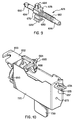
- Fig. 7 shows hcw a first service station 50 can be actuated by a media advance motor, and also identifies one frame of reference for use in pcsitioning a wiper unit in the first service station relative to the printhead and to the printer platen.
- the media advance system for an inkjet printer with a heated print zone such as the Hewlett-Packard DeskJet 1200 C inkjet printer includes a vertical support plate 600, a stepper motor 602, a main drive gear 604 which drives a first axle 606 carrying primary drivewheels 608, a secondary drive gear 610 which drives a seccnd axle 612 carrying secondary driveroller 614.
- Left and right bushing plates 616, 618 provide precise positioning of the drivewheels 608 and the driveroller 614 closely adjacent to a screen platen 620 which supports media passing through a heated print zone.
- the right bushing plate 618 is modified to provide precise positioning of a unique first service station unit which is located next to the right bushing plate.
- the right bushing plate includes a top hole 622 and a bottom hole 624 for positional mounting of the first service station unit.
- a service station drive gear 626 is fixedly mounted on the right end of second axle 612.
- a front datum projection 630 fits into matching slot 632 on a service station chassis 634, while a rear datum projection 636 fits into another matching slot 638.
- the service station chassis provides another frame of reference for positioning a wiper unit in the first service station relative to the printhead and to the printer platen.
- a housing 650 includes a front mounting tab 652 with screw slot 653, back mounting tab 654 with walls 655, 657, top bearing pin 656 for rotatably mounting top spur gear 658, bottom bearing pin 660 for rotatably mounting bottom spur gear 662, externally projecting mounting members (for holes 622, 624, respectively) such as a secondary top mounting pin 664 with spacer 665 and primary bottom mounting pin 666 with spacer 667, scraper 668, upper and lower cam surfaces 670, 672, and forward and rear bearing holes 673 for rotatably mounting a lead screw 674.
- a secondary top mounting pin 664 with spacer 665 and primary bottom mounting pin 666 with spacer 667, scraper 668, upper and lower cam surfaces 670, 672, and forward and rear bearing holes 673 for rotatably mounting a lead screw 674.
- a large opening 675 in the housing 650 allows drive gear 626 to extend through a housing wall for engagement with spur gear 658, thereby providing a gear train through bottom spur gear 662 to face gear 690.
- Chassis hole 677 is positioned for attaching alignment with screw slot 653, and chassis slot 679 is positioned for engagement with walls 655, 657.
- a nut member is provided to form a wiper base 676 which has upper and lower cam followers 678, 680 which respectively track upper and lower cam surfaces 670, 672 as the wiper base moves in a back-and-forth linear motion along a central threaded portion 682 of the lead screw 674.
- An upwardly projecting key shaft 684 on the wiper base 676 is shaped to engage a matching interior mounting channel 686 of a removable wiper blade 638.
- An extending toe 689 on the wiper base provides asymmetry to avoid assembling the wiper base facing in the wrong direction on the leadscrew.
- a face gear 690 is mounted on a square hub 692 of the lead screw 674 as the last element in a gear train to rotatably drive the lead screw.
- the lead screw 674 includes unthreaded front and back portions 694, 696 to provide temporary parking positions for the wiper base after it has traversed along the central threaded portion 682 during rotation of the lead screw by the face gear.
- a cover 720 is sized and shaped to fit together with the housing 650 to form a spittoon in the first service station.
- the cover includes a front spring arm (not shown) and a back spring arm 722 to urge the wiper base into engagement with the central threaded portion 682 during appropriate time periods of the wiping procedure.
- Arm hooks 724 are provided for engagement with matching slots on the housing, and tab plates 726 serve to hold the spur gears 658, 662 in position on the housing.
- slots 728 in both upper and lower cam surfaces 670, 672 allow ink to descend down into a bottom spittoon area (not shown) where an enlarged diaper pad absorbs excess ink.
- an elongated wicking member 730 extends downwardly from the housing to help draw residual liquid ink down and away from important moving printer parts and away from the print zone.
- the back-and-forth movement of the wiper member 688 also helps to avoid crippling buildup of ink in the spittoon.
- Wiper blade member 750 As shown in Figs. 12A-12B and 13, secure but removable attachment of a wiper blade member 750 made with an elastomer material such as EPDM rubber is provided by an end wall 740 and a lateral headwall 742 for receiving and engaging splayed head 744 on wiper base 634.
- Wiper blade member 750 includes successive wiper blades 752, 754 which are split to form separate spaced apart wiping sections 753, 755. Each section presents a rounded edge 756 and a sharp edge 758 to sequentially wick ink from orifices onto a nozzle surface of the printhead with the rounded wiper edge and immediately thereafter remove ink from the nozzle surface of the printhead with the sharp wiper edge.
- the rounded wiper edge By positioning the successive wiper blades in a mirror image orientation, the rounded wiper edge necessarily engages the nozzle surface first and the sharp edge engages the nozzle surface immediately thereafter. Thus, wet ink resolubalizes any dried ink on the nozzle surface, and the sharp edge immediately cleans the surface before any dried in buildup occurs.
- the aforementioned split configuration is particularly designed for use with inkjet nozzle arrays having two columns of ink orifices, such as a 1/3 inch swath printhead 802 with approximately one hundred nozzles in a 300 dpi array and/or a 1/2 inch swath printhead 804 with approximately three hundred nozzles in a 600 dpi array (see Fig. 15).
- the first service station provides for the unique wiping/scraping procedure as set forth in the flow chart of Figs. 16A-16B. It will be understood from the self-explanatory flow chart that initially the wiper blades are parked in an idle position with the wiper base in a home position on the unthreaded portion of the lead screw, even though the lead screw continues to rotate during a printing operation. After the printing operation is completed and the media is advanced out of the print zone, a scheduled wiping operation is commenced by reversing the stepper motor to activate the first service station.
- the flexible wiper blade edges are first driven across the rigid scraper to clean them in order to avoid damaging the nozzle surface, and then are driven across the ink orifices for the wicking/cleaning actions previously described.
- the cycle is completed by reversing the stepper motor to again accomplish the wicking/cleaning actions followed by the step of scraping the flexible wiper blade edges.
- the threaded wiper base then moves into an idle or parked position due to the clutch action of the unthreaded portion of the lead screw.
- the various datum mechanical interconnects precisely position the wiping mechanism of the first service station. If the media advance axis is called the X-axis, then primary positioning in the X direction is provided by lower pin 666. A first rotational positioning is provided by wall 657 and tab 652. A second rotational positioning is provided primarily by spacers 665, 667. Additional rotational positioning about the Z-axis is provided by lower wall 655 and spacers 665, 667.
- this invention allows higher resolution and speed to occur for frequently printed features such as text and the most frequent color components of graphics -- viz, black.
- frequently printed features such as text and the most frequent color components of graphics -- viz, black.
- the entire page is faster and of higher quality and is more comparable with laser printing performance (8+ pages per minute) and laser printing quality (600 dpi resolution).
Landscapes
- Ink Jet (AREA)
Abstract
Description
- This application relates generally to inkjet printing, and more particularly to online service station functions of spitting ink into a spittoon, wiping ink orifices, capping an array of nozzles on a printhead, and priming inkjet cartridges,
- Some prior color inkjet pen cartridges functioned somewhat satisfactorily with no wiping and minimal capping. Other prior monochrome/color inkjet cartridges used in single cartridge printers were wiped and capped with relatively simple mechanisms of the type shown in U.S. Patent No.4,583,717. Complex problems arose when trying to service different types of printheads on multiple ink cartridges mounted together in a print carrriage, particularly when the ink cartridges have different types of color/black inks.
- An inkjet printer has a printhead mounted in a carriage which periodically moves along a printhead path in a carriage scan direction to a stop position in a service station where an actuation device imparts translational motion to a wiper blade. The wiper blade moves along a linear wiping path orthogonal to the printhead path and across ink orifices on a nozzle surface of the printhead during a wiping operation. The wiper blade is removably mounted on a base and is split to form a first blade for wiping one column of ink orifices and a second blade for simultaneously wiping another column of ink orifices on a nozzle surface of the printhead.
- In a preferred form of the invention, the service station provides different sequential wiping steps with successive wiper blades by first drawing ink onto the nozzle surface from the ink orifices with a rounded blade edge of a leading wiper blade, and then wiping the ink from the nozzle surface with a sharp blade edge of a following wiper blade. The sequential wiping steps are repeated twice during a normal wiping cycle -- once when the wiper blades leave a parking location to wipe across the stationary printhead, and again when the wiper blades change direction to wipe back across the same stationary printhead to return to the parking location located away from the printhead path.
- Fig, 1 is a perspective view of a type of inkjet printer which can incorporate the service station features of the present invention;
- Fig. 2 is a perspective view of the carriage of the inkjet printer of Fig. 1, with yellow (Y), magenta (M), cyan (C) and black (K) inkjet cartridges removably mounted in the carriage;
- Fig. 3 is a close-up perspective view of a presently preferred embodiment of a service station unit which has been installed in the inkjet printer of Fig. 1;
- Figs. 4A and 4B are tabular and schematic representations showing the allocation of printhead services between first and second service stations which are incorporated in the service station unit of Fig. 3;
- Fig. 5 is a perspective view of a housing portion of the service station unit of Fig. 3, with certain functional components of the second service station shown in dotted lines;
- Fig. 6 is an exploded view of the functional service station components of the second service station, previously shown in dotted lines in Fig. 5;
- Fig. 7 is a perspective view showing a media advance drive roller system for a print zone, with a first service station drive gear mounted on one end of a media advance drive axle;
- Fig. 8 is an exploded view of a first service station;
- Fig. 9 shows a wiper base on a lead screw of the first service station;
- Fig. 10 is a perspective view of a first service station ready for installation on the printer, with a wiper unit in parked position;
- Fig. 11 is a perspective view of a housing portion of the first service station;
- Figs. 12A and 12B are enlarged perspective top and bottom views, respectively, of a wiper blade component of the first service station;
- Fig. 13 is a partially sectional view showing an interior mounting channel of the wiper blade component of Figs. 12A and 12B;
- Fig. 14 is a partial side view of a wiper base showing a key shaft for engagement with the interior mounting channel of Fig. 13;
- Fig. 15 schematically shows the nozzle arrays for a
wide swath 600 dpi black ink printhead and anarrow swath 300 dpi color ink printhead, respectively, which can be serviced by the service station methods and techniques of the present invention; - Figs. 16A and 16B are a flow chart showing the service station methods and techniques of the first service station; and
- Fig. 17 is a timing diagram for a complete wiping cycle of the first service station.
- In a presently preferred embodiment of the invention disclosed herein, we have combined a 600
dpi 1/2 inch swath black pen with three 300 dpi color pens each generating a swath of approximately 1/3 inch. The high performance black pen has pigment based ink and is typically used for printing text and other "black only" features, and thus the output quality and throughput of these features is greater. It also improves the output quality of color graphics and color features by teaming with the three lower resolution color pens which have dye based inks for printing color graphics or color features. The black component of the graphics is often a large portion of color graphics content is at a higher resolution and thus at a higher cutout quality level. The larger swath of the black pen can thus be combined with printing algorithms to improve the throughput of color graphics. - Even though the invention can be used in any printing environment where text and/or graphics are applied to media using monochrome and/or color components, the presently preferred embodiment of the invention is used in an inkjet printer of the type shown in FIG. 1. In particular,
inkjet printer 10 includes aninput tray 12 containing sheets ofmedia 14 which pass through a print zone, and are fed past anexit 18 into anoutput tray 16. Referring to FIGS. 1-2, amovable carriage 20 holdsprint cartridges support bumper 30 which rides along aguide 32 while the back of the carriage has multiple bushings such as 34 which ride alongslide rod 36. The position of the carriage as it traverses back and forth across the media is determined from an encoder strip 38 in order to be sure that the various ink nozzles on each print cartridge are selectively fired at the appropriate time during a carriage scan. - Of course, the invention is applicable to printers wherein cartridge printheads are completely or partially staggered relative to each other in the direction of the media advance axis in order to provide better throughput, avoid color bleed, etc. or may be in direct alignment to provide overlapping swaths during a single pass of the carriage over a print zone. The invention provides a unique way for selectively servicing only certain individual cartridges during a given time period, or for performing some service activities at one station and other service activities at another, or for performing all services at the same time in the same station, regardless of the staggered or aligned relationship of the printheads, and all without removing the printhead cartridges from a print carriage, as described in more detail below.
- While not limited to ink printheads have a particular type, size, resolution or configuration, the illustrated embodiment of the invention is used with ink cartridges having a dcuble column of ink orifices which extend in the media advance axis of the printer (see Fig. 15).
- In the illustrated embodiment, wiping of the three color printheads is accomplished in a conventional manner by stationary wipers having a narrow blade portion with a top edge for rubbing across the nozzle plate as the print cartridge moves past the wipers. Scraping the stationary wipers is also accomplished in a conventional manner by using a snout edge of the moving printhead. Capping of the three color ink printheads (as well as for the black ink printhead) is accomplished in a conventional manner by a capper having four sets of perimeter lips for completely surrounding the orifice pattern without overlapping any outer edge of the nozzle plate. Priming of the three color ink printheads (as well as for the black ink printhead) is acccmplished in a conventional manner by a vacuum primer.
- However, as shown in Figs. 3 and 4A-4B, the service station functicns of the present invention are generally divided between a
first service station 50 which is immediately on the right of aprint zone 51 and asecond service station 52 which is on the right of the first service station. The service functions of each are set fort in tabular form in Fig. 4A, and shown schematically in Fig. 4B. The direction of the translational back-and-forth wiping of the 600 dpi pigment based black ink printhead is identified byarrow 54 which is orthogonal to the carriage scan axis. Moreover, ahome location 56 for parkingwiper blade member 688 during an actual printing operation is located away fromprinthead path 58, to avoid interference with any of the printheads which extend into the service station section of the printer at the end of each printing swath. - Referring now to Figs. 3, 5 and 6, the
second service station 52 includes sled 60 having abar 61 forholding caps carriage 20 is not being used for printing and is not in position at the first service station, the carriage moves all the way to the right to enable the caps to engage their respective printhead nozzle surfaces, thereby preventing the ink orifices in the printhead from drying out. - A
wiper support structure 69 rests on thesled 60. Threewiper blades frame 76 for the CYM printheads, respectively, to remove contaminants or crusted ink that may block the printhead nozzles. Each wiper is dedicated exclusively to only one of the color ink printheads, whilewiper blade member 688 in the first service station is dedicated exclusively to only the black ink printhead. - The second service station also provides for selective priming each individual CYMK printhead by moving a
selection lever 78 to align with an appropriate cartridge, and then manually depressingplunger 80. Air is drawn through one offilters central apertures - The "spitting" function for all four printheads is handled by the first service station. This is particularly important when cartridges have been capped for a lengthy period of time. Before resuming printing, a series of ink drops are fired in a spitting operation to clear crusted ink from the nozzles. Such spitting can be scheduled to correlate with a wiping operation for the black ink cartridge in the first station, as well as with a wiping operation for the color ink cartridges in the second station.
- The perspective view of Fig. 7 shows hcw a
first service station 50 can be actuated by a media advance motor, and also identifies one frame of reference for use in pcsitioning a wiper unit in the first service station relative to the printhead and to the printer platen. In that regard, the media advance system for an inkjet printer with a heated print zone such as the Hewlett-Packard DeskJet 1200 C inkjet printer includes avertical support plate 600, astepper motor 602, amain drive gear 604 which drives afirst axle 606 carryingprimary drivewheels 608, asecondary drive gear 610 which drives aseccnd axle 612 carryingsecondary driveroller 614. Left andright bushing plates drivewheels 608 and thedriveroller 614 closely adjacent to ascreen platen 620 which supports media passing through a heated print zone. - In the present invention, the
right bushing plate 618 is modified to provide precise positioning of a unique first service station unit which is located next to the right bushing plate. The right bushing plate includes atop hole 622 and abottom hole 624 for positional mounting of the first service station unit. A servicestation drive gear 626 is fixedly mounted on the right end ofsecond axle 612. Afront datum projection 630 fits into matchingslot 632 on aservice station chassis 634, while arear datum projection 636 fits into anothermatching slot 638. Thus the service station chassis provides another frame of reference for positioning a wiper unit in the first service station relative to the printhead and to the printer platen. - The structural details of the first service station unit are best shown in Figs. 8-11. A
housing 650 includes afront mounting tab 652 withscrew slot 653, back mountingtab 654 withwalls top bearing pin 656 for rotatably mountingtop spur gear 658,bottom bearing pin 660 for rotatably mountingbottom spur gear 662, externally projecting mounting members (forholes top mounting pin 664 withspacer 665 and primarybottom mounting pin 666 withspacer 667,scraper 668, upper and lower cam surfaces 670, 672, and forward and rear bearing holes 673 for rotatably mounting alead screw 674. Alarge opening 675 in thehousing 650 allowsdrive gear 626 to extend through a housing wall for engagement withspur gear 658, thereby providing a gear train throughbottom spur gear 662 to facegear 690. Chassis hole 677 is positioned for attaching alignment withscrew slot 653, and chassis slot 679 is positioned for engagement withwalls - A nut member is provided to form a
wiper base 676 which has upper andlower cam followers portion 682 of thelead screw 674. An upwardly projectingkey shaft 684 on thewiper base 676 is shaped to engage a matchinginterior mounting channel 686 of aremovable wiper blade 638. An extendingtoe 689 on the wiper base provides asymmetry to avoid assembling the wiper base facing in the wrong direction on the leadscrew. - A
face gear 690 is mounted on asquare hub 692 of thelead screw 674 as the last element in a gear train to rotatably drive the lead screw. Thelead screw 674 includes unthreaded front andback portions portion 682 during rotation of the lead screw by the face gear. - A
cover 720 is sized and shaped to fit together with thehousing 650 to form a spittoon in the first service station. The cover includes a front spring arm (not shown) and aback spring arm 722 to urge the wiper base into engagement with the central threadedportion 682 during appropriate time periods of the wiping procedure. Arm hooks 724 are provided for engagement with matching slots on the housing, andtab plates 726 serve to hold the spur gears 658, 662 in position on the housing. To facilitate movement of thewiper member 688 back and forth along the lead screw,slots 728 in both upper and lower cam surfaces 670, 672 allow ink to descend down into a bottom spittoon area (not shown) where an enlarged diaper pad absorbs excess ink. Also, anelongated wicking member 730 extends downwardly from the housing to help draw residual liquid ink down and away from important moving printer parts and away from the print zone. The back-and-forth movement of thewiper member 688 also helps to avoid crippling buildup of ink in the spittoon. - As shown in Figs. 12A-12B and 13, secure but removable attachment of a
wiper blade member 750 made with an elastomer material such as EPDM rubber is provided by anend wall 740 and alateral headwall 742 for receiving and engaging splayedhead 744 onwiper base 634.Wiper blade member 750 includessuccessive wiper blades sections rounded edge 756 and asharp edge 758 to sequentially wick ink from orifices onto a nozzle surface of the printhead with the rounded wiper edge and immediately thereafter remove ink from the nozzle surface of the printhead with the sharp wiper edge. By positioning the successive wiper blades in a mirror image orientation, the rounded wiper edge necessarily engages the nozzle surface first and the sharp edge engages the nozzle surface immediately thereafter. Thus, wet ink resolubalizes any dried ink on the nozzle surface, and the sharp edge immediately cleans the surface before any dried in buildup occurs. The aforementioned split configuration is particularly designed for use with inkjet nozzle arrays having two columns of ink orifices, such as a 1/3 inch swath printhead 802 with approximately one hundred nozzles in a 300 dpi array and/or a 1/2inch swath printhead 804 with approximately three hundred nozzles in a 600 dpi array (see Fig. 15). - In accordance with all of the foregoing, the first service station provides for the unique wiping/scraping procedure as set forth in the flow chart of Figs. 16A-16B. It will be understood from the self-explanatory flow chart that initially the wiper blades are parked in an idle position with the wiper base in a home position on the unthreaded portion of the lead screw, even though the lead screw continues to rotate during a printing operation. After the printing operation is completed and the media is advanced out of the print zone, a scheduled wiping operation is commenced by reversing the stepper motor to activate the first service station. As the threads of the lead screw engage the wiper nut, the flexible wiper blade edges are first driven across the rigid scraper to clean them in order to avoid damaging the nozzle surface, and then are driven across the ink orifices for the wicking/cleaning actions previously described. The cycle is completed by reversing the stepper motor to again accomplish the wicking/cleaning actions followed by the step of scraping the flexible wiper blade edges. The threaded wiper base then moves into an idle or parked position due to the clutch action of the unthreaded portion of the lead screw. It is to be noted that while the accumulation of ink on a nozzle surface of the printhead is normally an undesirable thing, in this instance the wicking of ink from a nozzle array by the rounded edge of the leading wiper blade is very important here to achieve successful cleaning of the nozzle surface by lubricating the nozzle surface and by resolubalizing any residual dried ink on the nozzle surface.
- The different wiping speeds and the time required to perform each full wiping cycle in the preferred embodiment of the invention are shown in the timing diagram of Fig. 17. Thus, translational wiping is accomplished in both directions at different speeds as determined by print quality reliability standards.
- It will be appreciated by those skilled in the art that the various datum mechanical interconnects precisely position the wiping mechanism of the first service station. If the media advance axis is called the X-axis, then primary positioning in the X direction is provided by
lower pin 666. A first rotational positioning is provided bywall 657 andtab 652. A second rotational positioning is provided primarily byspacers lower wall 655 andspacers - By providing specialized wiping services to a high resolution wide swath pigment based black ink pen, this invention allows higher resolution and speed to occur for frequently printed features such as text and the most frequent color components of graphics -- viz, black. Thus by printing these frequent features and components faster and at a higher resolution, the entire page is faster and of higher quality and is more comparable with laser printing performance (8+ pages per minute) and laser printing quality (600 dpi resolution).
- It should be understood that the foregoing description is only illustrative of the invention and various alternatives and modifications may be made by those skilled in the art. Accordingly, the present invention is intended to include all such alternatives, modifications and variations which fall within the scope of the following claims.
Claims (10)
- An inkjet printer for use with at least one printhead with multiple orifices on a nozzle surface for applying liquid ink to media in a print zone, comprising:a frame;a service station on said frame;a carriage slidably mounted on said frame and movable in a carriage scan direction across the print zone to a stop position in said service station, with the printhead moving along a printhead path; anda wiper unit located in said service station and having a wiper member which moves in a linear direction across the multiple orifices to perform a wiping operation on the nozzle surface of the printhead when said carriage is in said step position in said service station.
- The inkjet printer of claim 1 wherein said wiper unit includes a wiper member which moves in a linear direction which is orthogonal to said carriage scan direction.
- The inkjet printer of claim 1 wherein said wiper unit includes a wiper member which moves back and forth across the nozzle surface of the printhead.
- The inkjet printer of claim 1 wherein said wiper member includes a plurality of successive wiper blades which are in close proximity to each other for sequential wiping of the same printhead in a forward wiping direction or both forward and reverse wiping directions.
- The inkjet printer of claim 4 wherein one of said successive wiper blades draws ink out of the ink orifices onto the nozzle surface, and another of said successive wiper blades wipes ink off the nozzle surface.
- The inkjet printer of any preceding claim, wherein the wiper member includes at least one rounded edge portion and at least one sharp edge portion such that initially wiping said printhead with said rounded edge portion draws ink onto said nozzle surface and subsequently wiping said printhead with said sharp edge portion wipes ink off said nozzle surface.
- The inkjet printer of any of claims 1 to 5, wherein said wiper member includes at least one resilient wiper with sufficient thickness to have a rounded edge portion and a sharp edge portion such that wiping said printhead in one direction with said resilient wiper.
- The inkjet printer of claim 1, wherein the printhead includes two columns of ink orifices extending in a given direction which is substantially parallel to said linear direction of movement of said wiper member, and wherein said wiper unit includes a wiper blade which is split to form a first edge portion for wiping one of said columns of ink orifices and a second edge portion for wiping another of said columns of ink orifices.
- A method of servicing an inkjet printhead having a printhead in a carriage which moves in a carriage scan direction along a printhead path through a print zone, comprising the following steps:transporting the carriage to a stop position in a printer service station without removing the printhead from the carriage; andmoving a wiper blade in the service station in a linear direction orthogonal to the carriage scan direction thereby wiping across ink orifices on a nozzle surface on the printhead.
- An inkjet printer system for applying ink to media in a print zone, comprising:a frame;a service station on said frame;a printhead;liquid ink;an ink reservoir for holding said liquid ink and connected with said printhead to supply said ink to multiple ink orifices on a nozzle surface of said printhead;a carriage for holding said printhead and slidably mounted on said frame for travelling in a carriage scan direction across the print zone to a stop position in said service station, with the printhead moving along a printhead path; anda wiper unit located in said service station and having a wiper member which moves in a linear direction across said multiple ink orifices to perform a wiping operation on the nozzle surface of the printhead when said carriage is in said stop position in said service station.
Applications Claiming Priority (2)
| Application Number | Priority Date | Filing Date | Title |
|---|---|---|---|
| US398709 | 1995-03-06 | ||
| US08/398,709 US5898445A (en) | 1995-03-06 | 1995-03-06 | Translational wiping technique for a stationary inkjet printhead |
Publications (3)
| Publication Number | Publication Date |
|---|---|
| EP0730965A2 true EP0730965A2 (en) | 1996-09-11 |
| EP0730965A3 EP0730965A3 (en) | 1996-09-18 |
| EP0730965B1 EP0730965B1 (en) | 1999-08-11 |
Family
ID=23576485
Family Applications (1)
| Application Number | Title | Priority Date | Filing Date |
|---|---|---|---|
| EP96301527A Expired - Lifetime EP0730965B1 (en) | 1995-03-06 | 1996-03-06 | Translational wiping technique for an inkjet printhead |
Country Status (4)
| Country | Link |
|---|---|
| US (1) | US5898445A (en) |
| EP (1) | EP0730965B1 (en) |
| DE (1) | DE69603634T2 (en) |
| ES (1) | ES2135167T3 (en) |
Cited By (1)
| Publication number | Priority date | Publication date | Assignee | Title |
|---|---|---|---|---|
| EP0860283A1 (en) * | 1997-02-19 | 1998-08-26 | Canon Kabushiki Kaisha | Ink jet recording apparatus, and method for recovering an ink jet recording head |
Families Citing this family (20)
| Publication number | Priority date | Publication date | Assignee | Title |
|---|---|---|---|---|
| US6193353B1 (en) * | 1995-03-06 | 2001-02-27 | Hewlett-Packard Company | Translational inkjet servicing module with multiple functions |
| US6113232A (en) * | 1997-12-19 | 2000-09-05 | Hewlett-Packard Company | Stationary pen printer |
| US6244685B1 (en) * | 1998-05-01 | 2001-06-12 | Canon Kabushiki Kaisha | Head wiping arrangement for ink jet printer |
| US6702423B2 (en) | 1998-05-27 | 2004-03-09 | Canon Kabushiki Kaisha | Cleaning device for inkjet printing head, cleaning method for inkjet printing head, inkjet recording apparatus, and wiper |
| US6785016B1 (en) * | 1999-05-25 | 2004-08-31 | Silverbrook Research Pty Ltd. | Portable interactive printer |
| US6585347B1 (en) | 2000-01-31 | 2003-07-01 | Hewlett-Packard Company | Printhead servicing based on relocating stationary print cartridges away from print zone |
| TW504463B (en) | 2000-04-28 | 2002-10-01 | Benq Corp | Inkjet head maintaining device for printing device |
| US6893110B2 (en) * | 2003-04-21 | 2005-05-17 | Hewlett-Packard Development Company, L.P. | Printer wiper blades based on surface energy |
| US20050035991A1 (en) * | 2003-08-12 | 2005-02-17 | Fredrickson Daniel John | Inkjet printer cleaning system and method |
| US7210761B2 (en) * | 2003-09-23 | 2007-05-01 | Hewlett-Packard Development Company, L.P. | Wiper apparatus and method for cleaning a printhead |
| US20070081020A1 (en) * | 2005-10-11 | 2007-04-12 | Jin-Sheng Lai | Printhead service station |
| JP5610768B2 (en) | 2006-10-31 | 2014-10-22 | センシエント・カラーズ・インコーポレーテッド | Modified pigment and method of making and using it |
| CA2697966C (en) | 2007-08-23 | 2018-11-06 | Sensient Colors Inc. | Self-dispersed pigments and methods for making and using the same |
| US8721632B2 (en) * | 2008-09-09 | 2014-05-13 | Tsunami Medtech, Llc | Methods for delivering energy into a target tissue of a body |
| CA2757928A1 (en) | 2009-04-07 | 2010-10-14 | Sensient Colors Inc. | Self-dispersing particles and methods for making and using the same |
| US8651657B2 (en) | 2010-10-21 | 2014-02-18 | Hewlett-Packard Development Company, L.P. | Printer module with bumper |
| US8622513B2 (en) * | 2011-04-18 | 2014-01-07 | Xerox Corporation | Using low pressure assist (LPA) to enable printhead maintenance system simplification |
| WO2019046695A1 (en) | 2017-08-31 | 2019-03-07 | Entrust Datacard Corporation | Drop-on-demand print head cleaning mechanism and method |
| JP7009301B2 (en) * | 2018-04-27 | 2022-01-25 | 株式会社ミマキエンジニアリング | Inkjet printing equipment |
| WO2019217878A1 (en) | 2018-05-11 | 2019-11-14 | Entrust Datacard Corporation | Card processing system with drop-on-demand print head automated maintenance routines |
Citations (3)
| Publication number | Priority date | Publication date | Assignee | Title |
|---|---|---|---|---|
| US4577203A (en) * | 1981-09-30 | 1986-03-18 | Epson Corporation | Ink jet recording apparatus |
| EP0585901A2 (en) * | 1992-09-02 | 1994-03-09 | Canon Kabushiki Kaisha | Ink jet apparatus provided with an improved recovery mechanism |
| EP0673772A1 (en) * | 1994-03-25 | 1995-09-27 | Hewlett-Packard Company | Orthogonal wiping system for ink jet print heads |
Family Cites Families (13)
| Publication number | Priority date | Publication date | Assignee | Title |
|---|---|---|---|---|
| JPS5945163A (en) * | 1982-09-08 | 1984-03-13 | Seiko Epson Corp | Ink jet printer |
| US5182582A (en) * | 1986-10-31 | 1993-01-26 | Canon Kabushiki Kaisha | Ink jet recording apparatus with cleaning means that cleans lighter-ink discharge portions before darker-ink discharge portions |
| US5148203A (en) * | 1989-09-18 | 1992-09-15 | Canon Kabushiki Kaisha | Ink jet recording apparatus including a drive mechanism for an ink ejection recovery systems |
| US5115250A (en) * | 1990-01-12 | 1992-05-19 | Hewlett-Packard Company | Wiper for ink-jet printhead |
| JPH03253347A (en) * | 1990-03-02 | 1991-11-12 | Canon Inc | Ink jet recorder |
| US5103244A (en) * | 1990-07-05 | 1992-04-07 | Hewlett-Packard Company | Method and apparatus for cleaning ink-jet printheads |
| JPH04187445A (en) * | 1990-11-21 | 1992-07-06 | Seiko Epson Corp | Ink jet printer |
| US5151715A (en) * | 1991-07-30 | 1992-09-29 | Hewlett-Packard Company | Printhead wiper for ink-jet printers |
| US5155497A (en) * | 1991-07-30 | 1992-10-13 | Hewlett-Packard Company | Service station for ink-jet printer |
| JPH06134998A (en) * | 1992-10-22 | 1994-05-17 | Canon Inc | Ink jet recorder |
| US5440331A (en) * | 1992-12-21 | 1995-08-08 | Hewlett-Packard Company | Printhead servicing apparatus |
| JPH06340081A (en) * | 1993-04-19 | 1994-12-13 | Xerox Corp | Printing head maintenance device for full-width ink jet printer |
| US5450105A (en) * | 1993-04-30 | 1995-09-12 | Hewlett-Packard Company | Manual pen selection for clearing nozzles without removal from pen carriage |
-
1995
- 1995-03-06 US US08/398,709 patent/US5898445A/en not_active Expired - Lifetime
-
1996
- 1996-03-06 ES ES96301527T patent/ES2135167T3/en not_active Expired - Lifetime
- 1996-03-06 DE DE69603634T patent/DE69603634T2/en not_active Expired - Lifetime
- 1996-03-06 EP EP96301527A patent/EP0730965B1/en not_active Expired - Lifetime
Patent Citations (3)
| Publication number | Priority date | Publication date | Assignee | Title |
|---|---|---|---|---|
| US4577203A (en) * | 1981-09-30 | 1986-03-18 | Epson Corporation | Ink jet recording apparatus |
| EP0585901A2 (en) * | 1992-09-02 | 1994-03-09 | Canon Kabushiki Kaisha | Ink jet apparatus provided with an improved recovery mechanism |
| EP0673772A1 (en) * | 1994-03-25 | 1995-09-27 | Hewlett-Packard Company | Orthogonal wiping system for ink jet print heads |
Cited By (2)
| Publication number | Priority date | Publication date | Assignee | Title |
|---|---|---|---|---|
| EP0860283A1 (en) * | 1997-02-19 | 1998-08-26 | Canon Kabushiki Kaisha | Ink jet recording apparatus, and method for recovering an ink jet recording head |
| US5984452A (en) * | 1997-02-19 | 1999-11-16 | Canon Kabushiki Kaisha | Ink jet recording apparatus, and a method for recovering an ink jet recording head |
Also Published As
| Publication number | Publication date |
|---|---|
| US5898445A (en) | 1999-04-27 |
| EP0730965A3 (en) | 1996-09-18 |
| ES2135167T3 (en) | 1999-10-16 |
| DE69603634T2 (en) | 1999-12-02 |
| EP0730965B1 (en) | 1999-08-11 |
| DE69603634D1 (en) | 1999-09-16 |
Similar Documents
| Publication | Publication Date | Title |
|---|---|---|
| EP0732211B1 (en) | Independent service stations for multiple printheads in inkjet printers | |
| EP0730965B1 (en) | Translational wiping technique for an inkjet printhead | |
| US5886714A (en) | Actuation mechanism for translational wiping of a stationary inkjet printhead | |
| US5793388A (en) | Customized printhead servicing for different printer conditions | |
| KR100516761B1 (en) | Hide-away wiper scraper for inkjet printhead | |
| US6193353B1 (en) | Translational inkjet servicing module with multiple functions | |
| US5432539A (en) | Printhead maintenance device for a full-width ink-jet printer including a wiper rotated by a lead screw | |
| US7252361B2 (en) | Ink jet recording apparatus having an ink absorbing member and a wiping member | |
| JP4939620B2 (en) | Service station and inkjet printer | |
| US6238035B1 (en) | Indexing scraper cleaning method and system for inkjet printheads and printing mechanism including the system | |
| US6755502B2 (en) | Sliced sponge scraper system for inkjet wipers | |
| EP1251007B1 (en) | Ink jet printer with maintenance device and maintenance method for the printer | |
| EP0621136A2 (en) | Wet-wipe maintenance device for a full-width ink jet printer | |
| EP0709203B1 (en) | Multiple wiper servicing system for inkjet printheads | |
| US6561619B1 (en) | Flipping wiper scraper system for inkjet printheads | |
| JP2002337351A (en) | Ink-jet recorder, method for controlling moving position of capping means therein, and method for controlling flushing therein | |
| US20090135226A1 (en) | Ink jet print head and ink jet printing apparatus | |
| JP2007130806A (en) | Inkjet recorder | |
| JP7170492B2 (en) | Inkjet printer, inkjet printer printing method | |
| KR100441588B1 (en) | maintenance apparatus having wiper cleaner-cleaning device in an ink-jet printer | |
| JP2002355991A (en) | Liquid drop discharge printer and method for refreshing printing head | |
| US20030202035A1 (en) | Independent wiping of printhead | |
| JPH081953A (en) | Cleaning device for ink jet recorder | |
| JPH07256887A (en) | Ink jet recorder | |
| JPH04214359A (en) | Ink jet recording device |
Legal Events
| Date | Code | Title | Description |
|---|---|---|---|
| PUAI | Public reference made under article 153(3) epc to a published international application that has entered the european phase |
Free format text: ORIGINAL CODE: 0009012 |
|
| PUAL | Search report despatched |
Free format text: ORIGINAL CODE: 0009013 |
|
| AK | Designated contracting states |
Kind code of ref document: A2 Designated state(s): DE ES GB |
|
| AK | Designated contracting states |
Kind code of ref document: A3 Designated state(s): DE ES GB |
|
| 17P | Request for examination filed |
Effective date: 19970317 |
|
| 17Q | First examination report despatched |
Effective date: 19971209 |
|
| GRAG | Despatch of communication of intention to grant |
Free format text: ORIGINAL CODE: EPIDOS AGRA |
|
| GRAG | Despatch of communication of intention to grant |
Free format text: ORIGINAL CODE: EPIDOS AGRA |
|
| GRAH | Despatch of communication of intention to grant a patent |
Free format text: ORIGINAL CODE: EPIDOS IGRA |
|
| GRAH | Despatch of communication of intention to grant a patent |
Free format text: ORIGINAL CODE: EPIDOS IGRA |
|
| GRAA | (expected) grant |
Free format text: ORIGINAL CODE: 0009210 |
|
| AK | Designated contracting states |
Kind code of ref document: B1 Designated state(s): DE ES GB |
|
| REF | Corresponds to: |
Ref document number: 69603634 Country of ref document: DE Date of ref document: 19990916 |
|
| REG | Reference to a national code |
Ref country code: ES Ref legal event code: FG2A Ref document number: 2135167 Country of ref document: ES Kind code of ref document: T3 |
|
| PLBE | No opposition filed within time limit |
Free format text: ORIGINAL CODE: 0009261 |
|
| STAA | Information on the status of an ep patent application or granted ep patent |
Free format text: STATUS: NO OPPOSITION FILED WITHIN TIME LIMIT |
|
| 26N | No opposition filed | ||
| REG | Reference to a national code |
Ref country code: GB Ref legal event code: 732E |
|
| REG | Reference to a national code |
Ref country code: GB Ref legal event code: IF02 |
|
| PGFP | Annual fee paid to national office [announced via postgrant information from national office to epo] |
Ref country code: ES Payment date: 20080326 Year of fee payment: 13 |
|
| REG | Reference to a national code |
Ref country code: ES Ref legal event code: FD2A Effective date: 20090307 |
|
| PG25 | Lapsed in a contracting state [announced via postgrant information from national office to epo] |
Ref country code: ES Free format text: LAPSE BECAUSE OF NON-PAYMENT OF DUE FEES Effective date: 20090307 |
|
| REG | Reference to a national code |
Ref country code: GB Ref legal event code: 732E Free format text: REGISTERED BETWEEN 20120329 AND 20120404 |
|
| PGFP | Annual fee paid to national office [announced via postgrant information from national office to epo] |
Ref country code: DE Payment date: 20130221 Year of fee payment: 18 Ref country code: GB Payment date: 20130228 Year of fee payment: 18 |
|
| REG | Reference to a national code |
Ref country code: DE Ref legal event code: R119 Ref document number: 69603634 Country of ref document: DE |
|
| GBPC | Gb: european patent ceased through non-payment of renewal fee |
Effective date: 20140306 |
|
| REG | Reference to a national code |
Ref country code: DE Ref legal event code: R119 Ref document number: 69603634 Country of ref document: DE Effective date: 20141001 |
|
| PG25 | Lapsed in a contracting state [announced via postgrant information from national office to epo] |
Ref country code: DE Free format text: LAPSE BECAUSE OF NON-PAYMENT OF DUE FEES Effective date: 20141001 Ref country code: GB Free format text: LAPSE BECAUSE OF NON-PAYMENT OF DUE FEES Effective date: 20140306 |