EP0585901A2 - Ink jet apparatus provided with an improved recovery mechanism - Google Patents
Ink jet apparatus provided with an improved recovery mechanism Download PDFInfo
- Publication number
- EP0585901A2 EP0585901A2 EP93113981A EP93113981A EP0585901A2 EP 0585901 A2 EP0585901 A2 EP 0585901A2 EP 93113981 A EP93113981 A EP 93113981A EP 93113981 A EP93113981 A EP 93113981A EP 0585901 A2 EP0585901 A2 EP 0585901A2
- Authority
- EP
- European Patent Office
- Prior art keywords
- ink
- recording head
- recording
- discharging
- ink supply
- Prior art date
- Legal status (The legal status is an assumption and is not a legal conclusion. Google has not performed a legal analysis and makes no representation as to the accuracy of the status listed.)
- Granted
Links
Images


Classifications
-
- B—PERFORMING OPERATIONS; TRANSPORTING
- B41—PRINTING; LINING MACHINES; TYPEWRITERS; STAMPS
- B41J—TYPEWRITERS; SELECTIVE PRINTING MECHANISMS, i.e. MECHANISMS PRINTING OTHERWISE THAN FROM A FORME; CORRECTION OF TYPOGRAPHICAL ERRORS
- B41J2/00—Typewriters or selective printing mechanisms characterised by the printing or marking process for which they are designed
- B41J2/005—Typewriters or selective printing mechanisms characterised by the printing or marking process for which they are designed characterised by bringing liquid or particles selectively into contact with a printing material
- B41J2/01—Ink jet
- B41J2/17—Ink jet characterised by ink handling
- B41J2/175—Ink supply systems ; Circuit parts therefor
-
- B—PERFORMING OPERATIONS; TRANSPORTING
- B41—PRINTING; LINING MACHINES; TYPEWRITERS; STAMPS
- B41J—TYPEWRITERS; SELECTIVE PRINTING MECHANISMS, i.e. MECHANISMS PRINTING OTHERWISE THAN FROM A FORME; CORRECTION OF TYPOGRAPHICAL ERRORS
- B41J2/00—Typewriters or selective printing mechanisms characterised by the printing or marking process for which they are designed
- B41J2/005—Typewriters or selective printing mechanisms characterised by the printing or marking process for which they are designed characterised by bringing liquid or particles selectively into contact with a printing material
- B41J2/01—Ink jet
- B41J2/135—Nozzles
- B41J2/165—Preventing or detecting of nozzle clogging, e.g. cleaning, capping or moistening for nozzles
- B41J2/16517—Cleaning of print head nozzles
- B41J2/1652—Cleaning of print head nozzles by driving a fluid through the nozzles to the outside thereof, e.g. by applying pressure to the inside or vacuum at the outside of the print head
- B41J2/16523—Waste ink collection from caps or spittoons, e.g. by suction
-
- B—PERFORMING OPERATIONS; TRANSPORTING
- B41—PRINTING; LINING MACHINES; TYPEWRITERS; STAMPS
- B41J—TYPEWRITERS; SELECTIVE PRINTING MECHANISMS, i.e. MECHANISMS PRINTING OTHERWISE THAN FROM A FORME; CORRECTION OF TYPOGRAPHICAL ERRORS
- B41J2/00—Typewriters or selective printing mechanisms characterised by the printing or marking process for which they are designed
- B41J2/005—Typewriters or selective printing mechanisms characterised by the printing or marking process for which they are designed characterised by bringing liquid or particles selectively into contact with a printing material
- B41J2/01—Ink jet
- B41J2/17—Ink jet characterised by ink handling
- B41J2/175—Ink supply systems ; Circuit parts therefor
- B41J2/17563—Ink filters
Definitions
- the present invention relates to an ink jet recording apparatus provided with a discharge recovery systems to eliminate from the discharging member the defective discharges brought about by the clogging due to dust particles and the increase of viscosity of ink, or the mixture of air bubbles or the like.
- Fig. 1 is a perspective view showing an example of the recording head used for an ink jet recording apparatus according to the prior art.
- a reference numeral 1 designates a discharging element comprising the ink passages in which the heat generating elements composed of HfB2 and others are integrally arranged in parallel for enabling discharging energy to act on the recording liquid (hereinafter referred to as ink); the open orifices 10 which are provided in the front part of each of the ink passages; and a common liquid chamber where the ink is retained for supply to each of the ink passages, among some others.
- the ink droplets are discharged from the orifices to execute an image formation.
- a reference numeral 3 designates a base plate on which the element 1 is adhesively bonded, and 2, a front plate fixed by bolts or other tightening members to the end faces of the discharging element 1 and base plate 3, having the apertures which enable the orifices 10 to face a recording medium such as a recording sheet directly.
- Each of the members 15, 16, and 17 is the one constituting a part of the ink supply systems; 15 is an elbow type connecting member which leads the ink into the common liquid chamber in the discharging element; 17 is a filter unit arranged on the way of the ink supply passages from an ink tank or the like which serves as an ink supply source; and 16 is a supply tube connecting between the connecting member 15 and the filter unit 17.
- Fig. 2 and Fig. 3 are cross-sectional views taken along the vertical and horizontal planes of the recording head shown in Fig. 1, respectively, which represent a state where a cap 4 is coupled to cover the entire surface of the aperture plane of the orifices 10 of the discharging element through the front plate 2 when a discharge recovery processing is executed.
- the ink passages 12 corresponding to a plurality of orifices 10 are connected to the so-called eave portion or appentice cave portions 13.
- the appentice cave portions 13 are connected to the common liquid chamber 14.
- a reference numeral 11 designates an energy generating element provided in the ink passage 12 to cause the discharging energy to act on the ink, which is formed by a heat generating element, for example.
- a filter 100 composed of ridge meshes, for example, is provided in order to remove fine dust particles and air bubbles.
- Fig. 4 is a block diagram showing the discharge recovery systems in an ink jet recording apparatus according to the prior art.
- the cap 4 In a usual recording state, the cap 4 is set in an appropriate position where it does not hinder any recording operation.
- a valve B2 is opened, while valves B1 and B3 are kept in the closed condition.
- Ink is supplied from the ink tank 6 to the discharging element 1 by the application of the capillary phenomenon through the valve B1.
- the cap 4 is installed on the discharging element 1. Then, at first, the valves B1, B2, and B3 are kept in the open state.
- a pump 7 is driven to send the ink from the ink tank 6 into the ink supply passages under pressure, thus circulating it through the ink tank 6 ⁇ ink supply passage L1 ⁇ discharging element 1 ⁇ ink supply passage L2 ⁇ ink tank in that order to remove air bubbles in the ink supply passages L1 and L2 as well as in the discharging element 1. Then, by closing the valve B1, the pressurized ink is supplied to the discharging element 1 so that the ink is forcibly discharged from the orifices 10.
- the fine dust particles, the over viscous ink resulting from the evaporation of the ink solvent, and the air bubbles contained in the ink, which are among those causes of the defective discharge, are all exhausted from the discharging element 1 together with the ink discharged from the orifices.
- the ingressive fine air bubbles a in the ink passages 12 are removed from the orifices 10 together with the ink when the pump 7 is driven.
- the ink thus discharged from the orifices 10 are received by the cap 4 and led out to a waste ink tank 5.
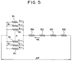
- Fig. 5 is a diagram showing the hydrodynamic equivalent circuit for ink in the conventional apparatus at the time of discharge recovery operation.
- the supply systems are designed to obtain the relationship of R1 » RH +
- the number of the nozzles n becomes great, and the flow rate per nozzle q becomes extremely small.
- the fluid resistance R1 in the nozzles in which the air bubbles or others exist becomes high. Therefore, the flow rate to the nozzle where the defective discharge takes place becomes still smaller than to the nozzle in the normal state.
- the nozzle which has brought about the defective discharge may not be restored to the normal condition, or the discharge recovery processing should be repeated before it is restored.
- the filter 100 provided for the ink supply passage is arranged to prevent the dust particles from being ingressive into the recording head 1 (the common liquid chamber 14 and ink passages 12) from the ink supply systems.
- the pressure loss will become greater at the time of discharging the ink, leading to the increased frequency of the defective discharge.
- the filter may be attempted to select the filter with a view to avoiding the defective discharges in the entire discharging ports while reducing the pressure loss.
- the required area of the filter becomes great particularly when the full-multi head having many numbers of discharging ports should be arranged. Therefore, the recording head 1 must inevitably be large in its size as the structure requires the filter to be arranged for the recording head 1 (in the common liquid chamber 14). This is a disadvantage encountered in this respect.
- the filter in a structure that the filter is installed on the way of the ink passage, it should be possible to adopt a filter having a large area comparatively easily, but there is still a disadvantage that the handling of the recording head 1 becomes inconvenient because it is necessary to keep the ink supply tube connected to the recording head 1 at all times. Moreover, the problems are encountered in that the assembling operation becomes difficult in the process of fabricating the recording head, and that there is a possibility that the dust particles can enter after the replacement of the heads if such a type is adopted as to make the detachment and replacement possible individually on the ink supply side and the recording head side.
- the present invention is designed with a view to solving the above-mentioned problems in the prior art. It is an object of the invention to provide an ink jet recording apparatus capable of executing a highly reliable and exact recovering process with which to recovery the abnormal ink discharging brought about by the clogging due to dust particles and others in the ink discharging apertures of the recording head, the increase in the viscosity of ink, the mixture of air bubbles, or the like, or to eliminate the causes of the abnormal ink discharging due to the ink droplets, foreign substances, or the like adhering to the circumference of the ink discharging apertures.
- It is another object of the present invention to provide an ink jet recording apparatus provided with a recording head having a plurality of discharging ports to discharge a recording liquid; capping means which can be installed on the recording head; pressure means for pressurizing the interior of the recording head by supplying the recording liquid under pressure to the ink supply passage connected to the recording head when the capping means is installed to cover the head; a first ink supply tube which conductively connects between the pressure means and the recording head; a second ink supply tube which conductively connects the recording head and the container which retains the recording liquid; a conductive tube which connects the first ink supply tube and second ink supply tube; and a control means which controls the flow in the conductive tube.
- It is a further object of the present invention to provide an ink jet recording apparatus comprising an ink jet recording means for discharging ink onto a recording material for recording in which electrothermal transducers, a common liquid chamber, liquid passages, and discharging ports are provided; a first substrate supported by a second substrate which has an ahead larger than that of the first substrate; a first filter connected to the common liquid chamber which is provided on both ends of a ceiling plate above the first substrate; a second filter connected to the first filter which is provided on both ends of the second substrate; and a detachable connecting means through which each of the second filter is connected to an ink tank.
- Fig. 1 is a perspective view schematically showing a structural example of an ink jet recording head.
- Fig. 2 is a vertical section of the ink jet recording head shown in Fig. 1.
- Fig. 3 is a horizontal section of the ink jet recording head shown in Fig. 1.
- Fig. 4 is a block diagram showing the ink supply recovery systems of an ink jet recording apparatus.
- Fig. 5 is a block diagram showing the hydrodynamic equivalent circuit of the ink supply recovery systems of an ink jet recording apparatus.
- Fig. 6 is a block diagram showing an example of the ink jet recording apparatus for which the present invention is adopted.
- Fig. 7 is a flowchart showing the recovery processing procedures.
- Fig. 8 is another example of the ink jet recording apparatus for which the present invention is adopted.
- Fig. 9 is a flowchart showing the recovery processing procedures.
- Fig. 10 is a cross-sectional view schematically showing another example of the ink jet recording apparatus for which the present invention is adopted.
- Fig. 11 is a cross-sectional view schematically showing still another example of the ink jet recording apparatus for which the present invention is adopted.
- Fig. 12 is a cross-sectional view schematically showing a further example of the ink jet recording apparatus for which the present invention is adopted.
- Fig. 13 is a cross-sectional view schematically showing still a further example of the ink jet recording apparatus for which the present invention is adopted.
- Fig. 14 is a cross-sectional view of the ink jet recording apparatus taken along the line A-A in Fig. 13.
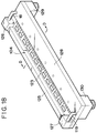
- Fig. 15 is a perspective view schematically showing a recording head for which the present invention is adopted.
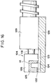
- Fig. 16 is a cross-sectional view of the recording head taken along the line B-B in Fig. 15.
- Fig. 17 is a horizontal section of the recording head shown in Fig. 15.
- Fig. 18 is a perspective view schematically showing a recording head for which the present invention is adopted.
- Fig. 19 is a cross-sectional view of the recording head taken along the line D-D in Fig. 18.
- Fig. 20 is a perspective view schematically showing an ink jet recording apparatus.
- Fig. 6 is a block diagram showing an example of the recovery systems of an ink jet recording apparatus according to the present invention.
- a reference numeral 8A designates an ink supply tube which connects an ink tank 6 and a discharging element 1 through a pump 7; 9B, an ink supply tube which connects the element 1 and ink tank 6; and 18, a conductive tube which connects the ink supply tube 8A and ink supply tube 9B.
- the valve B1 When any disabled discharge takes place in recording or air bubbles are generated in the ink supply passages while left intact for a long period, the valve B1 is closed at first, and then, ink is supplied by the pump 7 under pressure from the ink tank 6 in the direction indicated by an arrow a .
- the ink is supplied in the passages in the following two routes: the ink tank 6 ⁇ pump 7 ⁇ ink supply tube 8A ⁇ discharging element 1 ⁇ nozzles 12, and the ink tank 6 ⁇ pump 7 ⁇ ink tank 8A ⁇ conductive tube 18 ⁇ ink supply tube 9B ⁇ discharging element 1 ⁇ nozzles 12.
- the air bubbles generated in the tubes, the air bubbles mixed in the nozzles, and the like are all exhausted to the exterior through the nozzles.
- the ink is pressurized in the filter unit 17 which is attached to the discharging element 1 before the ink flows out from the ink passage, thus solving the problem that the air bubbles are still retained in the filter unit 17.
- the valve B1 is released to enable the ink to flow in the direction indicated by an arrow b so that the ink flows also in the ink supply tube 9B between the conductive tube 18 and the ink tank 6, thus filling the ink in the entire ink supply systems reliably.
- Fig. 7 is a flowchart showing an example of the recording and discharge recovery processing procedures of an ink jet apparatus according to the present invention.
- step S31 whether the apparatus is in use for a long time or not is determined. If the printing is ready, the valve B1 is released (step S32), and then, the ink is supplied from the ink tank 6 by the capillary phenomenon to the discharging element 1 through the ink supply tube 9B and conductive tube 18 for printing on a recording medium (step S33). If it is found that the apparatus is not in use for a long time in the step S31 or any defective printing is found in the step S34, the cap unit 4 is at first installed on the recording head H (step S35) in order to prevent the apparatus from being stained even if the ink overflows out of the ink passages.
- step S36 the valve B1 is closed (step S36), and the pump 7 is driven (step S37).
- step S37 the pressurized ink is conducted in the passages from the pump 7 to the discharging element 1 through the ink supply tube 8A, conductive tube 18, and ink supply tube 9B.
- the ink is ejected from the orifices 10 to remove the dust particles, air bubbles, and others which have caused the defective discharging.
- step S38 Whether this state has been kept continuously in a given period of time (here, a seconds) or not is determined (step S38). After a given time has elapsed, the valve B1 is released (step S39) to conduct the pressurized ink also into the passages from the valve B1 ⁇ ink supply tube 9B ⁇ ink tank 6. As a result, the ink is reliably filled in the ink passages. Further, in step S40, whether this state has been kept continuously in a given period of time (here, b seconds). After the given time has elapsed, the pump 7 is suspended (step S41), and the cap unit 4 is caused to retract from the discharging element 1 (step S42). Thus, the printing is terminated.
- a given period of time here, a seconds
- the present invention is extremely effective and is, of course, easily applicable to a recording head having a mode in which a plurality of the ink passages are arranged irrespective of the range of the arrangement or the number of the heads which corresponds to the entire width of a recording medium or to those having the arrangement or the number which is less than the foregoing ones; or to the heads for a multi type printer or a serial printer; or, further, in any cases irrespective of the structures of the ink supply systems.
- Fig. 8 is a block diagram showing an example of the recovery systems according to an embodiment of the ink jet recording apparatus of the present invention.
- a reference numeral 8A designates an ink supply tube which connects an ink tank 6 and a discharging element 1 through a pump 7; 9b, an ink supply tube which connects the discharging element 1 and the ink tank 6; and 18, a conductive tube which connects the ink supply tube 8A and ink supply tube 9B.
- the recovery operation is divided into two, and the description will be made of the operations in each case.
- the first mode is concerned with a case where the defective recording takes place due to the ingressive air bubbles in the ink passage or the adhesion of dust particles or the like to the orifices.
- no air bubbles are mixed in the ink supply systems, and thus, the ink is filled. Then, it will suffice if only just a little amount of ink is allowed to flow out from the ink passages. Therefore, the valve B1 is at first released. Further, the valve B2 is closed.
- the pump 7 is driven to allow the ink to circulate in the direction indicated by an arrow a , that is, the ink tank 6 ⁇ pump 7 ⁇ ink supply tube 8A ⁇ common liquid chamber ⁇ ink supply tube 9B ⁇ ink tank 6.
- the ink tank 6 ⁇ pump 7 ⁇ ink supply tube 8A ⁇ common liquid chamber ⁇ ink supply tube 9B ⁇ ink tank 6.
- the second mode is concerned with a case where the ink jet recording apparatus is not in use for a long time and is left intact so that the air bubbles are retained in the ink supply tubes, or a considerable amount of air bubbles are mixed in the ink supply tubes when the recording heads are replaced due to some trouble or some other reasons.
- the pump 7 is driven as if in the first mode, the ink cannot be circulated sufficiently due to the resultant pressure loss brought about by the flow out of ink from many of the ink passages or the air bubbles remain in the filter unit.
- the ink cannot pass through the filter unit at all. In such a case as this, therefore, the valve B1 is closed at first, and then, the valve B2 is released.
- the pump 7 is driven to circulate the pressurized ink through the route in the direction indicated by an arrow b: the ink tank 6 ⁇ pump 7 ⁇ ink supply tube 8A ⁇ common liquid chamber, and the ink tank 6 ⁇ pump 7 ⁇ ink supply tube 8A ⁇ conductive tube 18 ⁇ ink supply tube 9B ⁇ common liquid chamber.
- the ink tank 6 ⁇ pump 7 ⁇ ink supply tube 8A ⁇ conductive tube 18 ⁇ ink supply tube 9B ⁇ common liquid chamber.
- valve B1 is released to make the flow possible from the ink supply tube 9B ⁇ the ink tank 6 in the direction indicated by an arrow c to cause all the air bubbles remaining in that section to return to the ink tank 6. Then, the ink is filled in the passages.
- the pump 7 is suspended subsequent to the operations described above, and the valves B1 and B2 are released, thus making the printing ready at any time.
- Fig. 9 is a flowchart showing an example of the recording head and discharge recovery processing procedures.
- step S1 whether a large amount of air bubbles are mixed in the ink supply passages is determined when the apparatus is out of use for a long time or the heads are replaced.
- step S1 if it is found that no air bubbles are mixed in the ink supply passages, the printing is possible immediately.
- the valves B1 and B2 are released (step S2) to make ready the ink supply from the ink tank 6 by the capillary phenomenon to the discharging element 1 through the ink supply tube 9B and conductive tube 18 (step S3).
- step S4 whether any defective printing has taken place or not is determined.
- the cap unit 4 is installed on the recording head 1 at first (step S5) in order to prevent the apparatus from being stained even if the ink overflows from the nozzles. Then, the valve B2 is closed (step S6). The pump 7 is driven (step S7). At this juncture, the pressurized ink is conducted from the pump 7 to the discharging element 1 through the ink supply tube 8A, hence removing the air bubbles and others which have caused the defective discharging when the ink is ejected from the ink passages. However, the majority of the pressurized ink sent by the pump 7 is arranged to return from the discharging element 1 to the ink tank through the ink supply tube 9B at that time. Hence, the recovery operation can be executed with the least possible consumption of ink.
- Step S8 Whether this state has continued for a given period of time (here, a seconds) or not is determined (Step S8), and the pump 7 is suspended (step S9) to allow the cap unit 4 to retract from the discharging element 1 (step S10). Then, the valve B2 is released (step S11). In this state, whether or not the printing has finished is determined (step S12). If it is found that the printing has finished, the printing is terminated.
- step S1 when a considerable amount of the air bubbles is mixed in the ink supply passages because the apparatus is out of use for a long time, the recording heads are replaced, or the like, the cap unit 4 is installed to the recording head 1 (step S13) in order to prevent the apparatus from being stained even if the ink overflows from the ink passages. Then, the valve B1 is closed (step S14) while the valve B2 is released (step S15). The pump 7 is driven (step S16).
- the pressurized ink is conducted from the pump 7 to the passage connected to the discharging element 1 through the ink supply tube 8A, conductive tube 18, and ink supply tube 9B so that the air bubbles existing in the ink supply passages are all forced by pressure to flow out of the passages. Whether this state has continued for a given period of time (here, b seconds) or not is determined (step S17). If affirmative, the valve B1 is released (step S18) to conduct the pressurized ink also to the passage from the valve B1 ⁇ ink supply tube 9B ⁇ ink tank 6. As a result, the ink is filled in each of the ink passages reliably.
- step S19 whether this state has continued for a given period (here, c seconds) or not is determined. Then, the pump 7 is suspended (step S20) to allow the cap unit 4 to retract from the discharging element 1 (step S21). In step S22, whether the printing is executed or not is determined. If affirmative, the procedure will return to the step S3. If negative, the printing will be terminated.
- the present invention by the provision of a conductive tube which connects two ink supply tubes arranged for a discharging element, it becomes possible to provide at a low cost an ink supply systems capable of executing the recovery operation reliably by the pressure means as in the conventional systems even for a recording head having an extremely large number of nozzles.
- the ink supply systems capable of executing the recovery operation by the use of conventional pressure means reliably with the least possible consumption of ink required when a considerable amount of air bubbles are retained in the ink supply passages subsequent to the replacement of the recording heads or after the long period of time during which the heads are left intact, or the defective printing takes place due to the generation of fine air bubbles in the vicinity of the nozzles even for the recording head having an extremely large number of nozzles.
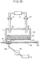
- Fig. 10 is a cross-sectional view schematically showing an example of the principal structure of a suction recovery mechanism only, and represents the structure of the recording head and ink suction unit at the time of a discharge recovery operation.
- This example comprises a recording head 1 having a plurality of ink discharging apertures 10 arranged in a straight line, and an ink suction unit which sucks ink from the orifices 10 when a discharge recovery operation is executed.
- the ink suction unit is provided with a sucking portion 8 which covers the aperture surface of a part of the orifices 10 among the plural orifices 10 in order to suck the ink therefrom, and a driving means comprising a guide screw 19 and a driving motor 20 which enable the sucking portion 8 to contact the surface of the orifices 10 and move thereon.
- a sucking portion 8 of the ink suction unit and the recording head 1 are arranged to abut upon or set apart from each other by allowing them to move correlatively.
- the recording operation is suspended, and the sucking portion 8 of the ink suction unit covers closely the orifice 10 portion on one end of the plural orifices 10 of the recording head 1 in order to suck ink by the sucking action of a pump 70 from the covered orifices 10.
- the sucking portion 8 is being moved to the orifice 10 portion on the other end on the surface of the orifices 10 for the suction of the ink, thus enabling the entire orifices 10 to discharge the ink one portion after another while cleaning the aperture surface in the sucking portion 8.
- the discharged ink and the foreign substances which have been cleaned off are collected into a waste ink tank 5 by the pump 7 through a waste ink tube 5A.
- the sucking portion 8 in addition to the structure which enables the sucking portion 8 to move on the surface of the orifices 10 from the one end of the orifice 10 portion to the other end of the orifice 10 portion, it may be possible to arrange a structure so that the sucking portion can be moved only in the vicinity of the orifices 10 where any defective discharge has taken place.
- the surface of the sucking portion 8 is preferable to form the surface of the sucking portion 8 with a resilient material.
- a resilient material For example, it is desirable to form the surface of the sucking portion 8 with a silicon rubber or some other material that may protect the orifices 10 from being damaged or protect itself from being damaged by the surface of the orifices 10 when moving thereon. Then, it will suffice for the suction area of the sucking portion 8 if only it can suck the ink from several tens of orifices.
- the optimal values are selective for the degree of pressure and the shifting speed of the sucking portion 8 on the surface of the orifices 10.
- Fig. 11 is a cross-sectional view schematically showing the principal part of another mode of the ink supply recovery systems of an ink jet recording apparatus.
- the sucking portion 8 of this example sucks ink from a part of the plural orifices, and then, a resilient blade 9 which is bent when abutting upon the surface of the orifices 10 is provided for the sucking portion 8.
- the sucking portion 8 cleans off by the use of the blade 9 the ink droplets, dust particles, and others from the orifice surface from the one end to the other end of the array of the orifices 10, while sucking the empty ink from the orifices 10 as moving to the last end of the orifice array.
- Fig. 12 is a cross-sectional view showing the principal part of another mode of the ink supply recovery systems.
- one of the side portions of the sucking portion 8 is formed by the blade 9 in this example in order to simplify the structure of the sucking portion 8.
- the simplified structure it is possible to obtain both the suction effect and the cleaning effect as well.
- the present invention is extremely effective and is, of course, easily executable for a recording head having a mode in which a plurality of the nozzles are arranged irrespective of the range of the arrangement or the number of the heads which corresponds to the entire width of a recording medium or to those having the arrangement or the number which is less than the foregoing ones; or to the heads for a multi type printer or a serial printer; or, further, in any cases irrespective of the structures of the ink supply systems.
- the detection of any defective discharge or the position of the orifices where a defective discharge has taken place may be conducted visually by the operator at the time of usual recording or test recording, or may be executed by the use of a read sensor or the like after having read the result of the test recording or the like on the recording medium.
- the required recovery operation is executed after having determined the presence of the defective discharge subsequent to the recording process in the foregoing example, it may be possible to execute the recovery operation for the discharging function immediately after the power source is turned on or before the initiation of recording after a long-time recess.
- a recording is executed by discharging ink from a plurality of ink discharging apertures of a recording head, and when a discharge recovery operation is executed to recover any abnormal ink discharge and others, the sucking portion provided for an ink suction unit is used to cover a part of the ink discharging apertures among a plurality of ink discharging apertures in order to suck the ink from the covered ink discharging apertures, and then, by use of the moving means which is arranged for the ink suction unit, the sucking portion is moved on the surface of the ink discharging apertures to suck the ink, thus sucking the ink from the entire ink discharging apertures, at the same time, cleaning off and collecting the ink droplets and foreign substances adhering to the circumference of the ink discharging apertures.
- the suction is given to the entire orifices one portion after another, not entirely at once, to enable them to discharge ink by the localized suction, thus making it possible to recover the discharging function effectively and perfectly.
- the above-mentioned mechanism can be arranged with a sucking portion smaller than the conventional one for covering a part of the ink discharging apertures among a plurality of discharging apertures of a recording head, and a driving means which enables the sucking portion to move on the surface of the ink discharging apertures; hence making it possible to implement the miniaturization of an apparatus and the reduction of the cost for the provision of an intended ink jet recording apparatus.
- a filter is arranged on a part of the ink supply passages of the ink supply systems of an ink jet recording apparatus in order to prevent the dust particles and other foreign substances mixed in the ink from being induced into the recording head.
- This filter can be adoptable in any one of the structures of the ink jet recording heads which have been described above. With the adoption of a filter of such a structure, it is possible to obtain a more stable condition under which the ink will be supplied.
- Fig. 13 is a horizontal section schematically showing the structure of a recording head 104 and an ink supply systems.
- Fig. 14 is a vertical section taken along the line A-A in Fig. 13.
- the ink jet recording head 104 comprises a plurality of the discharging ports 108 which discharge ink; liquid passages 109 connected to each of the discharging ports 108; electrothermal transducers (heat generating elements) 110 arranged in each of the liquid passages 109 to generate the thermal energy which is utilized for discharging ink; and a common liquid chamber 111 to supply ink to each of the liquid passages 109.
- the plural discharging ports 108 are arranged on the front end (discharging port formation surface) 122 of the recording head 104.
- each electrothermal transducer 110 is driven (energized) to generate film boiling in ink in the liquid passage 109 by the thermal energy generated at that time.
- the ink is discharged from the corresponding discharging port 108 onto a recording material for recording.
- a given space 0.5 to 1.5 mm, for example
- a reservoir tank (ink tank) 122 retaining ink is connected to the recording head 104 through a first ink supply tube 113 and a second ink supply tube 114 for supplying the ink.
- the first ink supply tube 113 forms a liquid passage on the pressurized flow side, and on the way thereof, a recovery pump 115 is installed.
- the second ink supply tube 114 forms the liquid passage on the returning flow side.
- first filters 116 and 117 are arranged on both end portions of the common liquid chamber 111. each of the first filters is connected to each of second filters 120 and 121 arranged on both sides of the recording head 4 by means of conductive passages 118 and 119, respectively.
- the first ink supply tube 113 is connected to the second filter 120 on one side, and the second ink supply tube 114 is connected to the second filter 121 on the other side. Therefore, when a recovery operation is executed, the aforesaid recovery pump 115 is actuated to supply the ink (under pressure) to the route from the reservoir tank 112 ⁇ first ink supply tube 113 ⁇ recovery pump 115 ⁇ second filter 120 ⁇ conductive passage 118 ⁇ first filter 116 ⁇ common liquid chamber 111. Further, the ink in the common liquid chamber 111 flows back to the reservoir tank 112 through the route from the first filter on the returning side 117 ⁇ conductive passage 119 ⁇ second filter 121 ⁇ second ink supply tube 114 ⁇ the reservoir tank 112.
- the ink when a recovery operation is executed, the ink is circulated through each of the ink supply tubes 113 and 114 and the common liquid chamber 111 so that the air bubbles and dust particles in the recording head 104 are removed. Also, in this circulation of ink, a part of the ink is exhausted from each of the discharging ports 108 in order to remove the ink which has become overly viscous and solidified in each of the liquid passages 109. Meanwhile, when a recording operation is executed, the ink is supplied to the common liquid chamber 111 through the second ink supply tube 114 because the flow resistance of the aforesaid recovery pump 115 is great.
- Fig. 15 is a perspective view showing the structure of an embodiment of the ink jet recording head 104 to which the present invention is applicable.
- Fig. 16 is a vertical section taken along the line B-B in Fig. 15.
- Fig. 17 is a partially plan section of the recording head shown in Fig. 15 which is cut horizontally.
- a plurality of electrothermal transducers (discharge heater) 110 and the wiring of aluminum and others for supplying electric power which are prepared by the application of the film formation technique are formed on a first substrate 123 made of silicon substrate and others.
- the liquid passages 109 are formed by a solid layer (made of epoxy resin or the like, for example) 124 corresponding to each of the electrothermal transducers 110. Then, on the solid layer 124, a ceiling plate 125 is bonded. With the recess in this ceiling plate 125, the aforesaid common liquid chamber 111 is formed for supplying ink to each of the liquid passages 109.
- first filter cases 126 and 127 are fixedly bonded to connect both end portions of the common liquid chamber 111 in the foregoing ceiling plate 125.
- the aforesaid first filters 116 and 117 are inserted into these filter cases.
- the first substrate 123 is positioned and bonded to the second substrate (the base plate of the recording head) 128, and is held fixedly on the second substrate.
- second filter cases 129 and 130 are fixed.
- the aforesaid second filters 120 and 121 are inserted into these filter cases.
- both end portions of the first filter cases 126 and 127 and the second filter cases 129 and 130 are connected by the aforesaid conductive passages 118 and 119.
- Each of the second filter cases 129 and 130 is easily and detachably joined to the first ink supply tube 113 and the second ink supply tube 114 by means of detachable tube fittings 131 and 134, respectively.
- each of the tube fittings 131 and 132 is connected to the recording head 104 so that the ink tank (reservoir tank) 112 and the recovery pump 115 are connected to the recording head 104, thus arranging the structure by which to supply or circulate the ink to the common liquid chamber 111 of the recording head 104.
- each of the first filter cases 126 and 127 is structured to be connected to the common liquid chamber 111 formed in the aforesaid ceiling plate 125.
- These first filter cases are easily coupled to both end portions of the ceiling plate 125, and further, these cases are made in a size not to allow them to extrude from the first substrate 123.
- the meshes of the first filters 116 and 117 in each of the first filter cases 126 and 127 are selected to be in a size so that the possible pressure loss will not affect the discharging capability when the ink is discharged from the entire discharging ports 108.
- the aforesaid second filter cases 129 and 130 and the second filters 120 and 121 in them are to prevent any dust particles in the exterior (in the ink or in the air) from entering the common liquid chamber 111 and each of the liquid passages 109.
- the second filter cases 129 and 130 are arranged on the second substrate 128 which has a larger area, thus making it possible for the second filters 120 and 121 to adopt finer meshes on a larger area, respectively.
- the meshes of the first filters 116 and 117 are selected to be larger than those of the second filers 120 and 121 while the effective areas of the first filters 116 and 117 are selected to be smaller than the effective areas of the second filters 120 and 121.
- the first filters 116 and 117 are arranged in the first filter cases 126 and 127 coupled to both end portions of the ceiling plate 125 which forms the common liquid chamber 111 of the recording head 104, the shape of the of the ceiling plate 125 becomes simple without any need for the formation of holes and complicated machining, and further, the size of the common liquid chamber 111 can be determined by the required volume at the time of full discharging. Therefore, it is possible to make the ceiling 125 small as well as to make the dimension of the first substrate 123 small, thus leading to the miniaturization of the recording head 104 and the reduction of the cost.
- the first filter cases 126 and 127 can be mounted when the first substrate 123, solid layer 124, and ceiling plate 125 are bonded together, for example. Consequently, it becomes possible in the following fabrication process to prevent dust particles to enter the common liquid chamber 111 and liquid passages 109 by the first filters 116 and 117 already mounted. In this respect, since a process of the kind is generally executed in a clean room, there is no need for making the meshes of the first filters 116 and 117 very small. Further, when the recording head 104 is used, it is possible to prevent dust particles from entering the common liquid chamber 111 and liquid passages 109 completely from the exterior by the effects of the double filters of the first ones 116 and 117 and the second ones 120 and 121.
- Fig. 18 is a perspective view showing the structure of another embodiment of the ink jet recording head to which the present invention is applicable.
- Fig. 19 is a vertical section taken along the line D-D in Fig. 18.
- the second filter cases 129 and 130 which house the second filters 120 and 121 are fixed to the surface on the side reverse to the surface of the second substrate 128 where the first substrate 123 is bonded as shown in Fig. 18 and Fig. 19.
- the second filter cases 129 and 130 are mounted on both sides of the lower end of the second substrate 128.
- the conductive tubes 118 and 119 which connect the first filter cases 126 and 127 and the second filter cases 129 and 130 are arranged to penetrate both end portions of the second substrate 128 vertically.
- the present embodiment differs from the foregoing embodiment in the above-mentioned aspects. All the other structures are essentially the same. Therefore, the parts corresponding to each other are referenced by the same marks, and the description will be omitted.
- the second filter cases 129 and 130 which are mounted on the second substrate 128 are arranged on the surface on the reverse side of the first substrate 123, thus enabling the configuration and size of the second filter cases 129 and 130 to be selected more freely as well as the dimension of the second substrate 128 in the longitudinal direction to be equal to the length of the first substrate 123.
- a case of a color ink jet recording apparatus provided with a plurality of recording means for recording in different colors is exemplified, but the present invention is equally applicable to an ink jet recording apparatus which records by one piece of the recording means, or an ink jet recording apparatus for gradation recording which uses a plurality of recording means for recording in the ink which has the same color but different densities, or the like, irrespective of the number of recording means (recording heads) and the combination thereof, and is capable of attaining the same functional effects.
- the present invention is equally applicable to the structure which uses an exchangeable cartridge type recording means having a recording head and ink tank integrally formed, and various other types of ink jet recording apparatuses irrespective of the structural modes of the recording head and ink tank, and is capable of obtaining the same effects.
- the double filters as described above are remarkably effective in applying them to a full-line recording head having many numbers of discharging ports arranged to cover the recordable width of a recording material width.
- the full-line head as many as approximately 2,000 to 4,000 discharging ports are arranged. Therefore, even when only one of the discharging ports becomes defective by the clogging or the like due to dust particles, the function of the entire head is adversely affected, and presents a problem of the unfavorable yield, hence leading to a serious problem cost-wise. Therefore, the ingressive dust particles in the liquid chamber and liquid passages must be reduced significantly by all means.
- Fig. 20 illustrates a case of the ink jet recording apparatus provided with a plurality of ink jet recording heads (in the represented example, four heads) of a line type capable of executing a full-color recording.
- Fig. 20 illustrates a case of the ink jet recording apparatus provided with a plurality of ink jet recording heads (in the represented example, four heads) of a line type capable of executing a full-color recording.
- reference numerals 201 and 202 designate the roller pairs which pinch a recording material 203 such as a paper sheet or plastic thin plate and convey (sheet feed) the recording material 203 in the sub-scanning direction (feeding direction) indicated by an arrow F; and 204B, 204Y, 204M, and 204C, the full-multi type ink jet recording heads (ink jet recording means) 204 in which the discharging ports are arranged essentially over the entire width of the recording material 203, respectively.
- recording head (recording means) 204 simply.
- the colors of ink discharged from the above-mentioned four-recording head 204 are black, yellow, magenta, and cyanogen, for example.
- the four-ink jet recording head 204 are arranged in that order from the upstream side of the feeding direction of the recording material (from the bottom in the example shown in Fig. 20).
- a reference numeral 206 designates the recovery systems which is arranged to prevent the defective ink discharge from each of the recording head 204.
- each ink jet recording head 204 is installed on a head installation unit 207 in such a manner as to correlatively regulate the position of each of them.
- an ink jet recording apparatus to which the present invention is applicable, that is, the ink jet recording apparatus having the head installation unit 207 to install the ink jet recording head 204, and feeding means 201 and 202 to convey a recording material 203 to the recording position of the recording head 204 installed in the aforesaid head installation unit 207, is structured.
- An ink jet recording apparatus comprises a recording head having a plurality of discharging ports to discharge a recording liquid; capping means capable of being mounted on the recording head; pressure means to enable the recording liquid to flow under pressure in the ink supply passages to the recording head, and pressurize the interior of the recording head when the capping means is mounted; a first ink supply tube to conductively connect the pressure means and the recording head; a second ink supply tube to conductively connect the recording head and a recording liquid reservoiring container; a conductive tube to conductively connect the first ink supply tube and the second ink supply tube; and control means to control the flow in the conductive tube, hence making it possible to remove air bubbles in the ink supply systems and ink passages easily and effectively by providing a conductive tube for the conventional ink supply systems.
Abstract
Description
- The present invention relates to an ink jet recording apparatus provided with a discharge recovery systems to eliminate from the discharging member the defective discharges brought about by the clogging due to dust particles and the increase of viscosity of ink, or the mixture of air bubbles or the like.
- Fig. 1 is a perspective view showing an example of the recording head used for an ink jet recording apparatus according to the prior art. Here, a
reference numeral 1 designates a discharging element comprising the ink passages in which the heat generating elements composed of HfB₂ and others are integrally arranged in parallel for enabling discharging energy to act on the recording liquid (hereinafter referred to as ink); theopen orifices 10 which are provided in the front part of each of the ink passages; and a common liquid chamber where the ink is retained for supply to each of the ink passages, among some others. Thus, the ink droplets are discharged from the orifices to execute an image formation. Areference numeral 3 designates a base plate on which theelement 1 is adhesively bonded, and 2, a front plate fixed by bolts or other tightening members to the end faces of thedischarging element 1 andbase plate 3, having the apertures which enable theorifices 10 to face a recording medium such as a recording sheet directly. Each of themembers member 15 and thefilter unit 17. - Fig. 2 and Fig. 3 are cross-sectional views taken along the vertical and horizontal planes of the recording head shown in Fig. 1, respectively, which represent a state where a
cap 4 is coupled to cover the entire surface of the aperture plane of theorifices 10 of the discharging element through thefront plate 2 when a discharge recovery processing is executed. - The
ink passages 12 corresponding to a plurality oforifices 10 are connected to the so-called eave portion orappentice cave portions 13. Theappentice cave portions 13 are connected to the commonliquid chamber 14. Areference numeral 11 designates an energy generating element provided in theink passage 12 to cause the discharging energy to act on the ink, which is formed by a heat generating element, for example. In thefilter unit 17, afilter 100 composed of ridge meshes, for example, is provided in order to remove fine dust particles and air bubbles. - Fig. 4 is a block diagram showing the discharge recovery systems in an ink jet recording apparatus according to the prior art. In a usual recording state, the
cap 4 is set in an appropriate position where it does not hinder any recording operation. At the same time, a valve B2 is opened, while valves B1 and B3 are kept in the closed condition. Ink is supplied from theink tank 6 to thedischarging element 1 by the application of the capillary phenomenon through the valve B1. When a discharge recovery operation is executed, thecap 4 is installed on thedischarging element 1. Then, at first, the valves B1, B2, and B3 are kept in the open state. In this state, apump 7 is driven to send the ink from theink tank 6 into the ink supply passages under pressure, thus circulating it through theink tank 6 → ink supply passage L₁ →discharging element 1 → ink supply passage L₂ → ink tank in that order to remove air bubbles in the ink supply passages L₁ and L₂ as well as in thedischarging element 1. Then, by closing the valve B1, the pressurized ink is supplied to thedischarging element 1 so that the ink is forcibly discharged from theorifices 10. - At this juncture, the fine dust particles, the over viscous ink resulting from the evaporation of the ink solvent, and the air bubbles contained in the ink, which are among those causes of the defective discharge, are all exhausted from the
discharging element 1 together with the ink discharged from the orifices. For example, as shown in Fig. 3, the ingressive fine air bubbles a in theink passages 12 are removed from theorifices 10 together with the ink when thepump 7 is driven. The ink thus discharged from theorifices 10 are received by thecap 4 and led out to awaste ink tank 5. - Fig. 5 is a diagram showing the hydrodynamic equivalent circuit for ink in the conventional apparatus at the time of discharge recovery operation. Here, given the pressure exerted by the
pump 7 as ΔP; the number of nozzles, as n; the fluid resistance per nozzle of thenozzles 12, as R1; fluid resistance in theappentice caves 13, as RH; fluid resistance in the commonliquid chamber 14, as RC; fluid resistance in thefilter unit 17, as RF; fluid resistance in any portions between theink tank 6 to the commonliquid chamber 14 other than thefilter unit 17, as RS; and flow rate per one nozzle of thenozzles 12 when pressurized by the pressure ΔP, as q, the following relationship will be satisfied at the time of discharge recovery operation:


Usually, the supply systems are designed to obtain the relationship of
nozzles 12 are arranged in a number corresponding to the recording width, that is, the so-called full-multi type recording head, the number of the nozzles n becomes great, and the flow rate per nozzle q becomes extremely small. Also, as shown in Fig. 8, if there exist ingressive air bubbles a, dust particles, and the like in thenozzles 12, the fluid resistance R1 in the nozzles in which the air bubbles or others exist becomes high. Therefore, the flow rate to the nozzle where the defective discharge takes place becomes still smaller than to the nozzle in the normal state. - As a result, when the conventional recovery systems are employed, the nozzle which has brought about the defective discharge may not be restored to the normal condition, or the discharge recovery processing should be repeated before it is restored.
- Also, it is necessary to make the pressure greater in order to overcome such a fluid resistance as this. Hence, there may be a need for the provision of a
greater pump 7, leading to the increased consumption of ink, and still more, to the enhancement of the strength of each connecting part between the members to enable them to withstand the increased pressure. - Also, in the conventional discharge recovery systems, although the air bubbles, dust particles, and others in the nozzles can be removed, it is still difficult to completely remove the dust particles and ink droplets adhering to the circumference of the apertures for discharging.
- Meanwhile, the
filter 100 provided for the ink supply passage is arranged to prevent the dust particles from being ingressive into the recording head 1 (the commonliquid chamber 14 and ink passages 12) from the ink supply systems. The smaller the meshes of a filter of the kind, its effectiveness is greater, but the smaller the meshes of the filter, the greater becomes the fluid resistance RF in the filter portion. Thus, the pressure loss will become greater at the time of discharging the ink, leading to the increased frequency of the defective discharge. - To counteract this, it may be attempted to select the filter with a view to avoiding the defective discharges in the entire discharging ports while reducing the pressure loss. In this case, however, the required area of the filter becomes great particularly when the full-multi head having many numbers of discharging ports should be arranged. Therefore, the
recording head 1 must inevitably be large in its size as the structure requires the filter to be arranged for the recording head 1 (in the common liquid chamber 14). This is a disadvantage encountered in this respect. Also, in a structure that the filter is installed on the way of the ink passage, it should be possible to adopt a filter having a large area comparatively easily, but there is still a disadvantage that the handling of therecording head 1 becomes inconvenient because it is necessary to keep the ink supply tube connected to therecording head 1 at all times. Moreover, the problems are encountered in that the assembling operation becomes difficult in the process of fabricating the recording head, and that there is a possibility that the dust particles can enter after the replacement of the heads if such a type is adopted as to make the detachment and replacement possible individually on the ink supply side and the recording head side. - The present invention is designed with a view to solving the above-mentioned problems in the prior art. It is an object of the invention to provide an ink jet recording apparatus capable of executing a highly reliable and exact recovering process with which to recovery the abnormal ink discharging brought about by the clogging due to dust particles and others in the ink discharging apertures of the recording head, the increase in the viscosity of ink, the mixture of air bubbles, or the like, or to eliminate the causes of the abnormal ink discharging due to the ink droplets, foreign substances, or the like adhering to the circumference of the ink discharging apertures.
- It is another object of the present invention to provide an ink jet recording apparatus provided with a recording head having a plurality of discharging ports to discharge a recording liquid; capping means which can be installed on the recording head; pressure means for pressurizing the interior of the recording head by supplying the recording liquid under pressure to the ink supply passage connected to the recording head when the capping means is installed to cover the head; a first ink supply tube which conductively connects between the pressure means and the recording head; a second ink supply tube which conductively connects the recording head and the container which retains the recording liquid; a conductive tube which connects the first ink supply tube and second ink supply tube; and a control means which controls the flow in the conductive tube.
- It is still another object of the present invention to provide an ink jet recording apparatus provided with a recording head having a plurality of ink discharging apertures, and an ink suction unit to suck the ink in the ink discharging apertures, in which the foregoing ink suction unit comprising a sucking portion which covers a part of the ink discharging apertures, among such plurality of the ink discharging apertures, in order to suck the ink, and a shifting means which shifts the sucking portion along the surface of the ink discharging apertures.
- It is a further object of the present invention to provide an ink jet recording apparatus comprising an ink jet recording means for discharging ink onto a recording material for recording in which electrothermal transducers, a common liquid chamber, liquid passages, and discharging ports are provided; a first substrate supported by a second substrate which has an ahead larger than that of the first substrate; a first filter connected to the common liquid chamber which is provided on both ends of a ceiling plate above the first substrate; a second filter connected to the first filter which is provided on both ends of the second substrate; and a detachable connecting means through which each of the second filter is connected to an ink tank.
- Fig. 1 is a perspective view schematically showing a structural example of an ink jet recording head.
- Fig. 2 is a vertical section of the ink jet recording head shown in Fig. 1.
- Fig. 3 is a horizontal section of the ink jet recording head shown in Fig. 1.
- Fig. 4 is a block diagram showing the ink supply recovery systems of an ink jet recording apparatus.
- Fig. 5 is a block diagram showing the hydrodynamic equivalent circuit of the ink supply recovery systems of an ink jet recording apparatus.
- Fig. 6 is a block diagram showing an example of the ink jet recording apparatus for which the present invention is adopted.
- Fig. 7 is a flowchart showing the recovery processing procedures.
- Fig. 8 is another example of the ink jet recording apparatus for which the present invention is adopted.
- Fig. 9 is a flowchart showing the recovery processing procedures.
- Fig. 10 is a cross-sectional view schematically showing another example of the ink jet recording apparatus for which the present invention is adopted.
- Fig. 11 is a cross-sectional view schematically showing still another example of the ink jet recording apparatus for which the present invention is adopted.
- Fig. 12 is a cross-sectional view schematically showing a further example of the ink jet recording apparatus for which the present invention is adopted.
- Fig. 13 is a cross-sectional view schematically showing still a further example of the ink jet recording apparatus for which the present invention is adopted.
- Fig. 14 is a cross-sectional view of the ink jet recording apparatus taken along the line A-A in Fig. 13.
- Fig. 15 is a perspective view schematically showing a recording head for which the present invention is adopted.
- Fig. 16 is a cross-sectional view of the recording head taken along the line B-B in Fig. 15.
- Fig. 17 is a horizontal section of the recording head shown in Fig. 15.
- Fig. 18 is a perspective view schematically showing a recording head for which the present invention is adopted.
- Fig. 19 is a cross-sectional view of the recording head taken along the line D-D in Fig. 18.
- Fig. 20 is a perspective view schematically showing an ink jet recording apparatus.
- Hereinafter, with reference to the accompanying drawings, the description will be made of the embodiments according to the present invention.
- Here, in each of the drawings of the embodiments, the same reference marks are provided for the corresponding parts of the constituent elements shown in the drawings illustrating the prior art, and the description thereof will be omitted.
- Fig. 6 is a block diagram showing an example of the recovery systems of an ink jet recording apparatus according to the present invention.
- Here, a
reference numeral 8A designates an ink supply tube which connects anink tank 6 and a dischargingelement 1 through apump 7; 9B, an ink supply tube which connects theelement 1 andink tank 6; and 18, a conductive tube which connects theink supply tube 8A andink supply tube 9B. - When any disabled discharge takes place in recording or air bubbles are generated in the ink supply passages while left intact for a long period, the valve B1 is closed at first, and then, ink is supplied by the
pump 7 under pressure from theink tank 6 in the direction indicated by an arrow a. In other words, the ink is supplied in the passages in the following two routes: theink tank 6 →pump 7 →ink supply tube 8A → dischargingelement 1 →nozzles 12, and theink tank 6 →pump 7 →ink tank 8A →conductive tube 18 →ink supply tube 9B → dischargingelement 1 →nozzles 12. In this way, the air bubbles generated in the tubes, the air bubbles mixed in the nozzles, and the like are all exhausted to the exterior through the nozzles. Also, the ink is pressurized in thefilter unit 17 which is attached to the dischargingelement 1 before the ink flows out from the ink passage, thus solving the problem that the air bubbles are still retained in thefilter unit 17. Then, the valve B1 is released to enable the ink to flow in the direction indicated by an arrow b so that the ink flows also in theink supply tube 9B between theconductive tube 18 and theink tank 6, thus filling the ink in the entire ink supply systems reliably. - Subsequently, the
pump 7 is suspended with the valve B1 kept in release. Then, the printing is ready at any time. - Fig. 7 is a flowchart showing an example of the recording and discharge recovery processing procedures of an ink jet apparatus according to the present invention.
- At first, in step S31, whether the apparatus is in use for a long time or not is determined. If the printing is ready, the valve B1 is released (step S32), and then, the ink is supplied from the
ink tank 6 by the capillary phenomenon to the dischargingelement 1 through theink supply tube 9B andconductive tube 18 for printing on a recording medium (step S33). If it is found that the apparatus is not in use for a long time in the step S31 or any defective printing is found in the step S34, thecap unit 4 is at first installed on the recording head H (step S35) in order to prevent the apparatus from being stained even if the ink overflows out of the ink passages. Then, the valve B1 is closed (step S36), and thepump 7 is driven (step S37). At this juncture, the pressurized ink is conducted in the passages from thepump 7 to the dischargingelement 1 through theink supply tube 8A,conductive tube 18, andink supply tube 9B. As a result, the ink is ejected from theorifices 10 to remove the dust particles, air bubbles, and others which have caused the defective discharging. - Whether this state has been kept continuously in a given period of time (here, a seconds) or not is determined (step S38). After a given time has elapsed, the valve B1 is released (step S39) to conduct the pressurized ink also into the passages from the valve B1 →
ink supply tube 9B →ink tank 6. As a result, the ink is reliably filled in the ink passages. Further, in step S40, whether this state has been kept continuously in a given period of time (here, b seconds). After the given time has elapsed, thepump 7 is suspended (step S41), and thecap unit 4 is caused to retract from the discharging element 1 (step S42). Thus, the printing is terminated. - As described above, just by arranging a conductive tube in the conventional ink supply systems, it becomes possible to remove the air bubbles in the ink supply systems and ink passages easily by means of a small pump. In this respect, the present invention is extremely effective and is, of course, easily applicable to a recording head having a mode in which a plurality of the ink passages are arranged irrespective of the range of the arrangement or the number of the heads which corresponds to the entire width of a recording medium or to those having the arrangement or the number which is less than the foregoing ones; or to the heads for a multi type printer or a serial printer; or, further, in any cases irrespective of the structures of the ink supply systems.
- Fig. 8 is a block diagram showing an example of the recovery systems according to an embodiment of the ink jet recording apparatus of the present invention.
- Here, a
reference numeral 8A designates an ink supply tube which connects anink tank 6 and a dischargingelement 1 through apump 7; 9b, an ink supply tube which connects the dischargingelement 1 and theink tank 6; and 18, a conductive tube which connects theink supply tube 8A andink supply tube 9B. - At first, the recovery operation is divided into two, and the description will be made of the operations in each case.
- The first mode is concerned with a case where the defective recording takes place due to the ingressive air bubbles in the ink passage or the adhesion of dust particles or the like to the orifices. In such a case as this, no air bubbles are mixed in the ink supply systems, and thus, the ink is filled. Then, it will suffice if only just a little amount of ink is allowed to flow out from the ink passages. Therefore, the valve B1 is at first released. Further, the valve B2 is closed. Then, the
pump 7 is driven to allow the ink to circulate in the direction indicated by an arrow a, that is, theink tank 6 →pump 7 →ink supply tube 8A → common liquid chamber →ink supply tube 9B →ink tank 6. At this juncture, by the ink flow from the common liquid chamber to the nozzles, it is possible to remove the air bubbles, dust particles, and the like in the nozzles easily. Also, since the majority of the pressurized ink by thepump 7 returns to theink tank 6 through the circulating route, no ink is wasted. - The second mode is concerned with a case where the ink jet recording apparatus is not in use for a long time and is left intact so that the air bubbles are retained in the ink supply tubes, or a considerable amount of air bubbles are mixed in the ink supply tubes when the recording heads are replaced due to some trouble or some other reasons. In this case, if the
pump 7 is driven as if in the first mode, the ink cannot be circulated sufficiently due to the resultant pressure loss brought about by the flow out of ink from many of the ink passages or the air bubbles remain in the filter unit. In the worst case, the ink cannot pass through the filter unit at all. In such a case as this, therefore, the valve B1 is closed at first, and then, the valve B2 is released. Subsequently, thepump 7 is driven to circulate the pressurized ink through the route in the direction indicated by an arrow b: theink tank 6 →pump 7 →ink supply tube 8A → common liquid chamber, and theink tank 6 →pump 7 →ink supply tube 8A →conductive tube 18 →ink supply tube 9B → common liquid chamber. At this juncture, all the air bubbles retained in the ink passages are forced by pressure to flow out from them. After the ink has been sent under pressure in a given period of time, the valve B1 is released to make the flow possible from theink supply tube 9B → theink tank 6 in the direction indicated by an arrow c to cause all the air bubbles remaining in that section to return to theink tank 6. Then, the ink is filled in the passages. - In either case of the first and second modes, the
pump 7 is suspended subsequent to the operations described above, and the valves B1 and B2 are released, thus making the printing ready at any time. - Fig. 9 is a flowchart showing an example of the recording head and discharge recovery processing procedures.
- At first, in step S1, whether a large amount of air bubbles are mixed in the ink supply passages is determined when the apparatus is out of use for a long time or the heads are replaced. In the step S1, if it is found that no air bubbles are mixed in the ink supply passages, the printing is possible immediately. Thus, the valves B1 and B2 are released (step S2) to make ready the ink supply from the
ink tank 6 by the capillary phenomenon to the dischargingelement 1 through theink supply tube 9B and conductive tube 18 (step S3). Then, in step S4, whether any defective printing has taken place or not is determined. If any defect occurs in printing, thecap unit 4 is installed on therecording head 1 at first (step S5) in order to prevent the apparatus from being stained even if the ink overflows from the nozzles. Then, the valve B2 is closed (step S6). Thepump 7 is driven (step S7). At this juncture, the pressurized ink is conducted from thepump 7 to the dischargingelement 1 through theink supply tube 8A, hence removing the air bubbles and others which have caused the defective discharging when the ink is ejected from the ink passages. However, the majority of the pressurized ink sent by thepump 7 is arranged to return from the dischargingelement 1 to the ink tank through theink supply tube 9B at that time. Hence, the recovery operation can be executed with the least possible consumption of ink. - Whether this state has continued for a given period of time (here, a seconds) or not is determined (Step S8), and the
pump 7 is suspended (step S9) to allow thecap unit 4 to retract from the discharging element 1 (step S10). Then, the valve B2 is released (step S11). In this state, whether or not the printing has finished is determined (step S12). If it is found that the printing has finished, the printing is terminated. Now, in the step S1, when a considerable amount of the air bubbles is mixed in the ink supply passages because the apparatus is out of use for a long time, the recording heads are replaced, or the like, thecap unit 4 is installed to the recording head 1 (step S13) in order to prevent the apparatus from being stained even if the ink overflows from the ink passages. Then, the valve B1 is closed (step S14) while the valve B2 is released (step S15). Thepump 7 is driven (step S16). At this juncture, the pressurized ink is conducted from thepump 7 to the passage connected to the dischargingelement 1 through theink supply tube 8A,conductive tube 18, andink supply tube 9B so that the air bubbles existing in the ink supply passages are all forced by pressure to flow out of the passages. Whether this state has continued for a given period of time (here, b seconds) or not is determined (step S17). If affirmative, the valve B1 is released (step S18) to conduct the pressurized ink also to the passage from the valve B1 →ink supply tube 9B →ink tank 6. As a result, the ink is filled in each of the ink passages reliably. Further, whether this state has continued for a given period (here, c seconds) or not is determined (step S19). Then, thepump 7 is suspended (step S20) to allow thecap unit 4 to retract from the discharging element 1 (step S21). In step S22, whether the printing is executed or not is determined. If affirmative, the procedure will return to the step S3. If negative, the printing will be terminated. - According to the present invention, by the provision of a conductive tube which connects two ink supply tubes arranged for a discharging element, it becomes possible to provide at a low cost an ink supply systems capable of executing the recovery operation reliably by the pressure means as in the conventional systems even for a recording head having an extremely large number of nozzles.
- Also, by the provision of a conductive tube connecting the two ink supply tubes arranged for the discharging element and a valve controlling the flow in the conductive tube in an ink jet recording apparatus having a plurality of orifices, it is possible to provide at a low cost the ink supply systems capable of executing the recovery operation by the use of conventional pressure means reliably with the least possible consumption of ink required when a considerable amount of air bubbles are retained in the ink supply passages subsequent to the replacement of the recording heads or after the long period of time during which the heads are left intact, or the defective printing takes place due to the generation of fine air bubbles in the vicinity of the nozzles even for the recording head having an extremely large number of nozzles.
- So far the description has been made of an improved recovery mechanism using a pressurized recovery mechanism, but it may be possible to use a suction recovery mechanism described below in addition to the pressurized one or in place thereof. With the mechanism having the following suction recovery mechanism in addition to the foregoing pressurized recovery mechanism, it is possible to implement a more reliable recovery performance.
- Fig. 10 is a cross-sectional view schematically showing an example of the principal structure of a suction recovery mechanism only, and represents the structure of the recording head and ink suction unit at the time of a discharge recovery operation.
- This example comprises a
recording head 1 having a plurality ofink discharging apertures 10 arranged in a straight line, and an ink suction unit which sucks ink from theorifices 10 when a discharge recovery operation is executed. - The ink suction unit is provided with a sucking
portion 8 which covers the aperture surface of a part of theorifices 10 among theplural orifices 10 in order to suck the ink therefrom, and a driving means comprising aguide screw 19 and a drivingmotor 20 which enable the suckingportion 8 to contact the surface of theorifices 10 and move thereon. Although not shown in Fig. 10, the suckingportion 8 of the ink suction unit and therecording head 1 are arranged to abut upon or set apart from each other by allowing them to move correlatively. - Hereinafter, the operation of this example will be described.
- When a recording operation has been executed longer than a given period of time or an abnormal ink discharge has taken place, among some other cases, which necessitates an issuance of discharge recovery instruction, the recording operation is suspended, and the sucking
portion 8 of the ink suction unit covers closely theorifice 10 portion on one end of theplural orifices 10 of therecording head 1 in order to suck ink by the sucking action of apump 70 from the coveredorifices 10. Then, by rotating theguide screw 19 of the driving means by use of the drivingmotor 20, the suckingportion 8 is being moved to theorifice 10 portion on the other end on the surface of theorifices 10 for the suction of the ink, thus enabling theentire orifices 10 to discharge the ink one portion after another while cleaning the aperture surface in the suckingportion 8. The discharged ink and the foreign substances which have been cleaned off are collected into awaste ink tank 5 by thepump 7 through awaste ink tube 5A. - The dust particles, the over viscous ink, the air bubbles, and the like in the
orifices 10, which are the causes of the abnormal discharge, are exhausted together with the discharged ink when the ink is discharged from theorifices 10, thus recovering the discharging function. In this respect, it is possible to recover the discharging function effectively and perfectly by the partial suction of ink which is orderly conducted, not the simultaneous suction of ink from theentire orifices 10. - Also, by shifting the sucking
portion 8 on the surface of theorifices 10, it is possible to clean off and collect the ink droplets and foreign substances adhering to the circumference of theorifices 10 for the elimination of the causes of the abnormal discharge. - In this respect, in addition to the structure which enables the sucking
portion 8 to move on the surface of theorifices 10 from the one end of theorifice 10 portion to the other end of theorifice 10 portion, it may be possible to arrange a structure so that the sucking portion can be moved only in the vicinity of theorifices 10 where any defective discharge has taken place. - Further, it is preferable to form the surface of the sucking
portion 8 with a resilient material. For example, it is desirable to form the surface of the suckingportion 8 with a silicon rubber or some other material that may protect theorifices 10 from being damaged or protect itself from being damaged by the surface of theorifices 10 when moving thereon. Then, it will suffice for the suction area of the suckingportion 8 if only it can suck the ink from several tens of orifices. Also, depending on the strength of theorifices 10, the surface strength of the suckingportion 8, the ink suction force, and others, the optimal values are selective for the degree of pressure and the shifting speed of the suckingportion 8 on the surface of theorifices 10. - Fig. 11 is a cross-sectional view schematically showing the principal part of another mode of the ink supply recovery systems of an ink jet recording apparatus.
- The sucking
portion 8 of this example sucks ink from a part of the plural orifices, and then, aresilient blade 9 which is bent when abutting upon the surface of theorifices 10 is provided for the suckingportion 8. - With the structure described above, the sucking
portion 8 cleans off by the use of theblade 9 the ink droplets, dust particles, and others from the orifice surface from the one end to the other end of the array of theorifices 10, while sucking the empty ink from theorifices 10 as moving to the last end of the orifice array. - In other words, by providing a
blade 9 on the front side in the direction in which the suckingportion 8 moves, it becomes possible to suck the ink from the orifices after having cleaned off the orifice surface, thus removing the air bubbles and others in thenozzles 12 reliably for an excellent printing to ensue. - Fig. 12 is a cross-sectional view showing the principal part of another mode of the ink supply recovery systems.
- As shown in Fig. 12, one of the side portions of the sucking
portion 8 is formed by theblade 9 in this example in order to simplify the structure of the suckingportion 8. Thus, with the simplified structure, it is possible to obtain both the suction effect and the cleaning effect as well. - In this respect, the present invention is extremely effective and is, of course, easily executable for a recording head having a mode in which a plurality of the nozzles are arranged irrespective of the range of the arrangement or the number of the heads which corresponds to the entire width of a recording medium or to those having the arrangement or the number which is less than the foregoing ones; or to the heads for a multi type printer or a serial printer; or, further, in any cases irrespective of the structures of the ink supply systems.
- Also, it is possible to arrange the structures of the sucking
portion 8, moving means, and others in some other way, not necessarily confined to the structures described in each of the foregoing embodiments. - Further, the detection of any defective discharge or the position of the orifices where a defective discharge has taken place, which is necessary for the issuance of an instruction for recovering the discharging function, may be conducted visually by the operator at the time of usual recording or test recording, or may be executed by the use of a read sensor or the like after having read the result of the test recording or the like on the recording medium. Further, although the required recovery operation is executed after having determined the presence of the defective discharge subsequent to the recording process in the foregoing example, it may be possible to execute the recovery operation for the discharging function immediately after the power source is turned on or before the initiation of recording after a long-time recess.
- As described above, by adopting this mechanism in addition to the foregoing pressurized recovery mechanism or by itself individually as has been exemplified, a recording is executed by discharging ink from a plurality of ink discharging apertures of a recording head, and when a discharge recovery operation is executed to recover any abnormal ink discharge and others, the sucking portion provided for an ink suction unit is used to cover a part of the ink discharging apertures among a plurality of ink discharging apertures in order to suck the ink from the covered ink discharging apertures, and then, by use of the moving means which is arranged for the ink suction unit, the sucking portion is moved on the surface of the ink discharging apertures to suck the ink, thus sucking the ink from the entire ink discharging apertures, at the same time, cleaning off and collecting the ink droplets and foreign substances adhering to the circumference of the ink discharging apertures.
- By enabling the ink to be discharged from the orifices, the dust particles, over viscous ink, air bubbles, and others in the orifices which have been the cause of the abnormal discharging are exhausted together with the discharged ink for the recovery of the discharging function. In this respect, the suction is given to the entire orifices one portion after another, not entirely at once, to enable them to discharge ink by the localized suction, thus making it possible to recover the discharging function effectively and perfectly.
- Also, by moving the sucking portion on the surface of the orifices, it is possible to clean off and collect the ink droplets and foreign substances adhering to the circumference of the orifices for the removal of the causes of the abnormal discharging, thus enabling a highly reliable discharge recovery process to be executed exactly.
- In this respect, it is possible to arrange a structure whereby to shift the sucking portion to the vicinity of the orifices in which the defective discharging has taken place besides the structure in which the sucking portion is arranged to move from the orifice portion on the one end to the other on the orifice surface.
- The above-mentioned mechanism can be arranged with a sucking portion smaller than the conventional one for covering a part of the ink discharging apertures among a plurality of discharging apertures of a recording head, and a driving means which enables the sucking portion to move on the surface of the ink discharging apertures; hence making it possible to implement the miniaturization of an apparatus and the reduction of the cost for the provision of an intended ink jet recording apparatus.
- Now, as described earlier, a filter is arranged on a part of the ink supply passages of the ink supply systems of an ink jet recording apparatus in order to prevent the dust particles and other foreign substances mixed in the ink from being induced into the recording head.
- Hereinafter, the description will be made of an optimal structure of the filter which can be adopted according to the present invention.
- This filter can be adoptable in any one of the structures of the ink jet recording heads which have been described above. With the adoption of a filter of such a structure, it is possible to obtain a more stable condition under which the ink will be supplied.
- Fig. 13 is a horizontal section schematically showing the structure of a
recording head 104 and an ink supply systems. Fig. 14 is a vertical section taken along the line A-A in Fig. 13. In Fig. 13 and Fig. 14, the inkjet recording head 104 comprises a plurality of the dischargingports 108 which discharge ink;liquid passages 109 connected to each of the dischargingports 108; electrothermal transducers (heat generating elements) 110 arranged in each of theliquid passages 109 to generate the thermal energy which is utilized for discharging ink; and acommon liquid chamber 111 to supply ink to each of theliquid passages 109. The plural dischargingports 108 are arranged on the front end (discharging port formation surface) 122 of therecording head 104. - Then, in accordance with image signals or discharging signals, each
electrothermal transducer 110 is driven (energized) to generate film boiling in ink in theliquid passage 109 by the thermal energy generated at that time. Thus, by the utilization of the change of states (pressure changes or the like) which brings about the aforesaid film boiling, the ink is discharged from the corresponding dischargingport 108 onto a recording material for recording. When this recording operation is executed, a given space (0.5 to 1.5 mm, for example) is set between the aforesaid dischargingport formation surface 122 and the recording material. - In Fig. 13 and Fig. 14, a reservoir tank (ink tank) 122 retaining ink is connected to the
recording head 104 through a firstink supply tube 113 and a secondink supply tube 114 for supplying the ink. the firstink supply tube 113 forms a liquid passage on the pressurized flow side, and on the way thereof, arecovery pump 115 is installed. The secondink supply tube 114 forms the liquid passage on the returning flow side. On the other hand, in therecording head 104,first filters common liquid chamber 111. each of the first filters is connected to each ofsecond filters recording head 4 by means ofconductive passages - Then, the first
ink supply tube 113 is connected to thesecond filter 120 on one side, and the secondink supply tube 114 is connected to thesecond filter 121 on the other side. Therefore, when a recovery operation is executed, theaforesaid recovery pump 115 is actuated to supply the ink (under pressure) to the route from thereservoir tank 112 → firstink supply tube 113 →recovery pump 115 →second filter 120 →conductive passage 118 →first filter 116 →common liquid chamber 111. Further, the ink in thecommon liquid chamber 111 flows back to thereservoir tank 112 through the route from the first filter on the returningside 117 →conductive passage 119 →second filter 121 → secondink supply tube 114 → thereservoir tank 112. - In other words, when a recovery operation is executed, the ink is circulated through each of the
ink supply tubes common liquid chamber 111 so that the air bubbles and dust particles in therecording head 104 are removed. Also, in this circulation of ink, a part of the ink is exhausted from each of the dischargingports 108 in order to remove the ink which has become overly viscous and solidified in each of theliquid passages 109. Meanwhile, when a recording operation is executed, the ink is supplied to thecommon liquid chamber 111 through the secondink supply tube 114 because the flow resistance of theaforesaid recovery pump 115 is great. - Fig. 15 is a perspective view showing the structure of an embodiment of the ink
jet recording head 104 to which the present invention is applicable. Fig. 16 is a vertical section taken along the line B-B in Fig. 15. Fig. 17 is a partially plan section of the recording head shown in Fig. 15 which is cut horizontally. In Fig. 13 to Fig. 17, a plurality of electrothermal transducers (discharge heater) 110 and the wiring of aluminum and others for supplying electric power which are prepared by the application of the film formation technique are formed on afirst substrate 123 made of silicon substrate and others. On thefirst substrate 123, theliquid passages 109 are formed by a solid layer (made of epoxy resin or the like, for example) 124 corresponding to each of theelectrothermal transducers 110. Then, on thesolid layer 124, aceiling plate 125 is bonded. With the recess in thisceiling plate 125, the aforesaidcommon liquid chamber 111 is formed for supplying ink to each of theliquid passages 109. - To the
first substrate 123,first filter cases common liquid chamber 111 in the foregoingceiling plate 125. The aforesaidfirst filters first substrate 123 is positioned and bonded to the second substrate (the base plate of the recording head) 128, and is held fixedly on the second substrate. To both end portions of thesecond substrate 128,second filter cases second filters first filter cases second filter cases conductive passages - Each of the
second filter cases ink supply tube 113 and the secondink supply tube 114 by means ofdetachable tube fittings 131 and 134, respectively. In other words, each of thetube fittings recording head 104 so that the ink tank (reservoir tank) 112 and therecovery pump 115 are connected to therecording head 104, thus arranging the structure by which to supply or circulate the ink to thecommon liquid chamber 111 of therecording head 104. - The interior of each of the
first filter cases common liquid chamber 111 formed in theaforesaid ceiling plate 125. These first filter cases are easily coupled to both end portions of theceiling plate 125, and further, these cases are made in a size not to allow them to extrude from thefirst substrate 123. Also, the meshes of thefirst filters first filter cases ports 108. - The aforesaid
second filter cases second filters common liquid chamber 111 and each of theliquid passages 109. The smaller the meshes of thesecond filters second filters second filter cases second substrate 128 which has a larger area, thus making it possible for thesecond filters first filters second filers first filters second filters - According to the above-mentioned embodiment, since the
first filters first filter cases ceiling plate 125 which forms thecommon liquid chamber 111 of therecording head 104, the shape of the of theceiling plate 125 becomes simple without any need for the formation of holes and complicated machining, and further, the size of thecommon liquid chamber 111 can be determined by the required volume at the time of full discharging. Therefore, it is possible to make theceiling 125 small as well as to make the dimension of thefirst substrate 123 small, thus leading to the miniaturization of therecording head 104 and the reduction of the cost. - Also, during the process of fabricating the
first substrate 123, thefirst filter cases first substrate 123,solid layer 124, andceiling plate 125 are bonded together, for example. Consequently, it becomes possible in the following fabrication process to prevent dust particles to enter thecommon liquid chamber 111 andliquid passages 109 by thefirst filters first filters recording head 104 is used, it is possible to prevent dust particles from entering thecommon liquid chamber 111 andliquid passages 109 completely from the exterior by the effects of the double filters of thefirst ones second ones - Fig. 18 is a perspective view showing the structure of another embodiment of the ink jet recording head to which the present invention is applicable. Fig. 19 is a vertical section taken along the line D-D in Fig. 18. In the present embodiment, the
second filter cases second filters second substrate 128 where thefirst substrate 123 is bonded as shown in Fig. 18 and Fig. 19. In other words, thesecond filter cases second substrate 128. Then, theconductive tubes first filter cases second filter cases second substrate 128 vertically. - The present embodiment differs from the foregoing embodiment in the above-mentioned aspects. All the other structures are essentially the same. Therefore, the parts corresponding to each other are referenced by the same marks, and the description will be omitted. According to the present embodiment, the
second filter cases second substrate 128 are arranged on the surface on the reverse side of thefirst substrate 123, thus enabling the configuration and size of thesecond filter cases second substrate 128 in the longitudinal direction to be equal to the length of thefirst substrate 123. As a result, according to the present embodiment, it is possible to obtain the effects that the prevention of the clogging due to dust particles in therecording head 104 is further improved, and at the same time, the further miniaturization of therecording head 104 becomes possible, in addition to the provision of the same effects as in the foregoing embodiment. - Also, in the foregoing embodiment, a case of a color ink jet recording apparatus provided with a plurality of recording means for recording in different colors is exemplified, but the present invention is equally applicable to an ink jet recording apparatus which records by one piece of the recording means, or an ink jet recording apparatus for gradation recording which uses a plurality of recording means for recording in the ink which has the same color but different densities, or the like, irrespective of the number of recording means (recording heads) and the combination thereof, and is capable of attaining the same functional effects. Further, in addition to the structure in which the recording head and ink tank are arranged separately and are connected by ink supply tubes or the like, the present invention is equally applicable to the structure which uses an exchangeable cartridge type recording means having a recording head and ink tank integrally formed, and various other types of ink jet recording apparatuses irrespective of the structural modes of the recording head and ink tank, and is capable of obtaining the same effects.
- The double filters as described above are remarkably effective in applying them to a full-line recording head having many numbers of discharging ports arranged to cover the recordable width of a recording material width. In the full-line head, as many as approximately 2,000 to 4,000 discharging ports are arranged. Therefore, even when only one of the discharging ports becomes defective by the clogging or the like due to dust particles, the function of the entire head is adversely affected, and presents a problem of the unfavorable yield, hence leading to a serious problem cost-wise. Therefore, the ingressive dust particles in the liquid chamber and liquid passages must be reduced significantly by all means.
- Hereinafter, in accordance with Fig. 20, the description will be made of the structural outline of an ink jet recording apparatus in which the recording head of the aforesaid structure is installed. Fig. 20 illustrates a case of the ink jet recording apparatus provided with a plurality of ink jet recording heads (in the represented example, four heads) of a line type capable of executing a full-color recording. In Fig. 20,
reference numerals recording material 203 such as a paper sheet or plastic thin plate and convey (sheet feed) therecording material 203 in the sub-scanning direction (feeding direction) indicated by an arrow F; and 204B, 204Y, 204M, and 204C, the full-multi type ink jet recording heads (ink jet recording means) 204 in which the discharging ports are arranged essentially over the entire width of therecording material 203, respectively. Here, in the following description, when any one of these recording heads is arbitrarily designated or all of them are designated, both of them are equally referred to as recording head (recording means) 204 simply. - In a case of a full-color recording, the colors of ink discharged from the above-mentioned four-
recording head 204 are black, yellow, magenta, and cyanogen, for example. In the example shown in Fig. 20, the four-inkjet recording head 204 are arranged in that order from the upstream side of the feeding direction of the recording material (from the bottom in the example shown in Fig. 20). Areference numeral 206 designates the recovery systems which is arranged to prevent the defective ink discharge from each of therecording head 204. When a discharge recovery operation (processing) is executed, this recovery means moves between each recordinghead 204 andrecording material 203 and faces therecording head 204 in place of therecording material 203, thus executing the recovery operation (recovery processing) for therecording head 204 as described earlier. Also, each inkjet recording head 204 is installed on ahead installation unit 207 in such a manner as to correlatively regulate the position of each of them. With the above, it is possible to structure an ink jet recording apparatus to which the present invention is applicable, that is, the ink jet recording apparatus having thehead installation unit 207 to install the inkjet recording head 204, and feeding means 201 and 202 to convey arecording material 203 to the recording position of therecording head 204 installed in the aforesaidhead installation unit 207, is structured. - An ink jet recording apparatus comprises a recording head having a plurality of discharging ports to discharge a recording liquid; capping means capable of being mounted on the recording head; pressure means to enable the recording liquid to flow under pressure in the ink supply passages to the recording head, and pressurize the interior of the recording head when the capping means is mounted; a first ink supply tube to conductively connect the pressure means and the recording head; a second ink supply tube to conductively connect the recording head and a recording liquid reservoiring container; a conductive tube to conductively connect the first ink supply tube and the second ink supply tube; and control means to control the flow in the conductive tube, hence making it possible to remove air bubbles in the ink supply systems and ink passages easily and effectively by providing a conductive tube for the conventional ink supply systems.
Claims (9)
- An ink jet recording apparatus, comprising:
a recording head having a plurality of discharging ports to discharge a recording liquid;
capping means capable of being mounted on said recording head;
pressure means to enable the recording liquid to flow under pressure in the ink supply passages to said recording head, and pressurize the interior of said recording head when said capping means is mounted;
a first ink supply tube to conductively connect said pressure means and said recording head;
a second ink supply tube to conductively connect said recording head and a recording liquid reservoiring container;
a conductive tube to conductively connect said first ink supply tube and said second ink supply tube; and
control means to control the flow in said conductive tube. - An ink jet recording apparatus, comprising:
a recording head having a plurality of discharging ports to discharge a recording liquid;
capping means capable of being mounted on said recording head;
pressure means to enable the recording liquid to flow under pressure in the ink supply passages to said recording head, and pressurize the interior of said recording head when said capping means is mounted;
a first ink supply tube to conductively connect said pressure means and said recording head;
a second ink supply tube to conductively connect said recording head and a recording liquid reservoiring container; and
a conductive tube to conductively connect said first ink supply tube and said second ink supply tube. - An ink jet recording apparatus according to Claim 1, wherein
said ink jet recording apparatus utilizes thermal energy to generate air bubbles in a recording liquid, and discharges recording droplets in accordance with the development of said air bubbles. - An ink jet recording head provided with a recording head having a plurality of ink discharging apertures, and an ink suction unit to suck ink from said ink discharging apertures, wherein
said ink suction unit comprises a sucking portion which covers a part of the ink discharging apertures of said plural ink discharging apertures, and sucks ink; and
driving means for moving said sucking portion on the surface of said ink discharging apertures. - An ink jet recording apparatus according to Claim 4, wherein
said driving means moves said sucking portion from the ink discharging aperture portion on one end of said recording head to the ink discharging aperture portion on the other end correlatively when the ink jet recording apparatus is not in the recording operation. - An ink jet recording apparatus according to Claim 4, wherein
the sucking portion of said ink suction unit is provided with a resilient material which is bent when abutting upon the surface of the ink discharging aperture portion, and said driving means enables said resilient material to abut upon the surface of the ink discharging apertures for bending, and moves said sucking portion on the surface of the ink discharging apertures when the ink jet recording apparatus is not in the recording operation. - An ink jet recording apparatus comprising ink jet recording means to record by discharging ink onto a recording material, wherein
said recording means has electrothermal transducers, a common liquid chamber, liquid passages, and discharging ports;
a first substrate is held by a second substrate which has an area larger than said first substrate;
first filters connected to said common liquid chamber are arranged on both ends of the ceiling plate on said first substrate;
second filters connected to said first filters are arranged on both ends of said second substrate; and
each of said second filters is connected to an ink tank through a detachable connecting means. - An ink jet recording apparatus according to Claim 7, wherein
the meshes of said first filters are larger than the meshes of said second filters. - An ink jet recording apparatus according to Claim 7, wherein
the effective area of said first filters are smaller than the effective area of said second filters.
Applications Claiming Priority (9)
| Application Number | Priority Date | Filing Date | Title |
|---|---|---|---|
| JP23466992 | 1992-09-02 | ||
| JP234669/92 | 1992-09-02 | ||
| JP23466992A JP3106013B2 (en) | 1992-09-02 | 1992-09-02 | Recovery method for inkjet recording device |
| JP280958/92 | 1992-09-25 | ||
| JP28095892A JP3105364B2 (en) | 1992-09-25 | 1992-09-25 | Ink jet recording head and ink jet recording apparatus |
| JP28095892 | 1992-09-25 | ||
| JP28757292 | 1992-10-26 | ||
| JP28757292A JP3065818B2 (en) | 1992-10-26 | 1992-10-26 | Ink jet recording device |
| JP287572/92 | 1992-10-26 |
Publications (3)
| Publication Number | Publication Date |
|---|---|
| EP0585901A2 true EP0585901A2 (en) | 1994-03-09 |
| EP0585901A3 EP0585901A3 (en) | 1995-05-03 |
| EP0585901B1 EP0585901B1 (en) | 1999-12-08 |
Family
ID=27332172
Family Applications (1)
| Application Number | Title | Priority Date | Filing Date |
|---|---|---|---|
| EP19930113981 Expired - Lifetime EP0585901B1 (en) | 1992-09-02 | 1993-09-01 | Ink jet apparatus provided with an improved recovery mechanism |
Country Status (2)
| Country | Link |
|---|---|
| EP (1) | EP0585901B1 (en) |
| DE (1) | DE69327209T2 (en) |
Cited By (12)
| Publication number | Priority date | Publication date | Assignee | Title |
|---|---|---|---|---|
| EP0730965A2 (en) * | 1995-03-06 | 1996-09-11 | Hewlett-Packard Company | Translational wiping technique for an inkjet printhead |
| US5594477A (en) * | 1994-11-30 | 1997-01-14 | Xerox Corporation | Wet wiper and vacuum primer configuration for full-width-array printbar |
| EP0764531A2 (en) * | 1995-09-22 | 1997-03-26 | Canon Kabushiki Kaisha | Liquid ejection head, apparatus and recovery method for them |
| EP0805035A2 (en) * | 1996-04-30 | 1997-11-05 | SCITEX DIGITAL PRINTING, Inc. | Attachable/detachable umbilical platform for a continuous ink jet printhead |
| EP0683050A3 (en) * | 1994-05-20 | 1998-01-07 | Canon Kabushiki Kaisha | Ink supplying apparatus and ink jet recording apparatus having same |
| US5886714A (en) * | 1995-03-06 | 1999-03-23 | Hewlett-Packard Company | Actuation mechanism for translational wiping of a stationary inkjet printhead |
| US5984450A (en) * | 1995-03-06 | 1999-11-16 | Hewlett-Packard Company | Inkjet printer having multiple printheads and multiple independent printhead service stations for performing different wiping procedures |
| EP1043161A2 (en) * | 1999-04-08 | 2000-10-11 | Seiko Epson Corporation | Ink jet recording apparatus and cleaning control method for recording head incorporated therein |
| CN1087228C (en) * | 1995-09-22 | 2002-07-10 | 佳能株式会社 | Liquid discharging method, liquid discharging head, liquid discharging apparatus, liquid container and head cartridge |
| US10124597B2 (en) | 2016-05-09 | 2018-11-13 | R.R. Donnelley & Sons Company | System and method for supplying ink to an inkjet printhead |
| US10137691B2 (en) | 2016-03-04 | 2018-11-27 | R.R. Donnelley & Sons Company | Printhead maintenance station and method of operating same |
| EP3674090A1 (en) * | 2018-12-28 | 2020-07-01 | Seiko Epson Corporation | Liquid ejecting head and liquid ejecting apparatus |
Families Citing this family (1)
| Publication number | Priority date | Publication date | Assignee | Title |
|---|---|---|---|---|
| US8888208B2 (en) | 2012-04-27 | 2014-11-18 | R.R. Donnelley & Sons Company | System and method for removing air from an inkjet cartridge and an ink supply line |
Citations (6)
| Publication number | Priority date | Publication date | Assignee | Title |
|---|---|---|---|---|
| US4153902A (en) * | 1976-11-19 | 1979-05-08 | Sharp Kabushiki Kaisha | Bubble removal in an ink liquid supply for an ink jet system printer |
| WO1988008370A1 (en) * | 1987-04-24 | 1988-11-03 | Siemens Aktiengesellschaft | Device for cleaning and closing the spray surface of an ink head |
| US4864329A (en) * | 1988-09-22 | 1989-09-05 | Xerox Corporation | Fluid handling device with filter and fabrication process therefor |
| JPH03277556A (en) * | 1990-03-28 | 1991-12-09 | Canon Inc | Ink jet recording device |
| US5128690A (en) * | 1989-01-11 | 1992-07-07 | Canon Kabushiki Kaisha | Recovery unit and method that expel foreign matter into a common liquid chamber of an ink jet head using a partial cap |
| EP0500068A2 (en) * | 1991-02-20 | 1992-08-26 | Canon Kabushiki Kaisha | Ink jet recording head, recording apparatus using same and method for manufacturing same |
-
1993
- 1993-09-01 EP EP19930113981 patent/EP0585901B1/en not_active Expired - Lifetime
- 1993-09-01 DE DE1993627209 patent/DE69327209T2/en not_active Expired - Lifetime
Patent Citations (6)
| Publication number | Priority date | Publication date | Assignee | Title |
|---|---|---|---|---|
| US4153902A (en) * | 1976-11-19 | 1979-05-08 | Sharp Kabushiki Kaisha | Bubble removal in an ink liquid supply for an ink jet system printer |
| WO1988008370A1 (en) * | 1987-04-24 | 1988-11-03 | Siemens Aktiengesellschaft | Device for cleaning and closing the spray surface of an ink head |
| US4864329A (en) * | 1988-09-22 | 1989-09-05 | Xerox Corporation | Fluid handling device with filter and fabrication process therefor |
| US5128690A (en) * | 1989-01-11 | 1992-07-07 | Canon Kabushiki Kaisha | Recovery unit and method that expel foreign matter into a common liquid chamber of an ink jet head using a partial cap |
| JPH03277556A (en) * | 1990-03-28 | 1991-12-09 | Canon Inc | Ink jet recording device |
| EP0500068A2 (en) * | 1991-02-20 | 1992-08-26 | Canon Kabushiki Kaisha | Ink jet recording head, recording apparatus using same and method for manufacturing same |
Non-Patent Citations (1)
| Title |
|---|
| PATENT ABSTRACTS OF JAPAN vol. 16, no. 103 (M-1221) 13 March 1992 & JP-A-03 277 556 (CANON INC) 9 December 1991 * |
Cited By (28)
| Publication number | Priority date | Publication date | Assignee | Title |
|---|---|---|---|---|
| EP0683050A3 (en) * | 1994-05-20 | 1998-01-07 | Canon Kabushiki Kaisha | Ink supplying apparatus and ink jet recording apparatus having same |
| US6120140A (en) * | 1994-05-20 | 2000-09-19 | Canon Kabushiki Kaisha | Ink supplying apparatus and ink recording apparatus having same |
| US5594477A (en) * | 1994-11-30 | 1997-01-14 | Xerox Corporation | Wet wiper and vacuum primer configuration for full-width-array printbar |
| DE19608487B4 (en) * | 1995-03-06 | 2014-05-15 | Hewlett-Packard Development Co., L.P. | Inkjet printer and method of servicing an inkjet printer |
| US5898445A (en) * | 1995-03-06 | 1999-04-27 | Hewlett-Packard Company | Translational wiping technique for a stationary inkjet printhead |
| EP0730965A2 (en) * | 1995-03-06 | 1996-09-11 | Hewlett-Packard Company | Translational wiping technique for an inkjet printhead |
| EP0730965A3 (en) * | 1995-03-06 | 1996-09-18 | Hewlett Packard Co | |
| US5984450A (en) * | 1995-03-06 | 1999-11-16 | Hewlett-Packard Company | Inkjet printer having multiple printheads and multiple independent printhead service stations for performing different wiping procedures |
| US5886714A (en) * | 1995-03-06 | 1999-03-23 | Hewlett-Packard Company | Actuation mechanism for translational wiping of a stationary inkjet printhead |
| US6505915B2 (en) | 1995-09-22 | 2003-01-14 | Canon Kabushiki Kaisha | Liquid ejection head, apparatus and recovery method for them |
| US6663230B2 (en) | 1995-09-22 | 2003-12-16 | Canon Kabushiki Kaisha | Liquid ejection head, apparatus and recovery method for them |
| EP0764531A2 (en) * | 1995-09-22 | 1997-03-26 | Canon Kabushiki Kaisha | Liquid ejection head, apparatus and recovery method for them |
| CN1087228C (en) * | 1995-09-22 | 2002-07-10 | 佳能株式会社 | Liquid discharging method, liquid discharging head, liquid discharging apparatus, liquid container and head cartridge |
| EP0764531A3 (en) * | 1995-09-22 | 1997-10-01 | Canon Kk | Liquid ejection head, apparatus and recovery method for them |
| AU714357B2 (en) * | 1996-04-30 | 1999-12-23 | Scitex Digital Printing, Inc. | Attachable/detachable umbilical platform |
| EP0805035A3 (en) * | 1996-04-30 | 1997-11-12 | SCITEX DIGITAL PRINTING, Inc. | Attachable/detachable umbilical platform for a continuous ink jet printhead |
| EP0805035A2 (en) * | 1996-04-30 | 1997-11-05 | SCITEX DIGITAL PRINTING, Inc. | Attachable/detachable umbilical platform for a continuous ink jet printhead |
| US6846062B2 (en) | 1999-04-08 | 2005-01-25 | Seiko Epson Corporation | Ink jet recording apparatus and cleaning control method for recording head incorporated therein |
| EP1043161A3 (en) * | 1999-04-08 | 2002-05-15 | Seiko Epson Corporation | Ink jet recording apparatus and cleaning control method for recording head incorporated therein |
| US7121652B2 (en) | 1999-04-08 | 2006-10-17 | Seiko Epson Corporation | Ink jet recording apparatus and cleaning control method for recording head incorporated therein |
| US7543907B2 (en) | 1999-04-08 | 2009-06-09 | Seiko Epson Corporation | Ink jet recording apparatus and cleaning control method for recording head incorporated therein |
| EP1043161A2 (en) * | 1999-04-08 | 2000-10-11 | Seiko Epson Corporation | Ink jet recording apparatus and cleaning control method for recording head incorporated therein |
| US10137691B2 (en) | 2016-03-04 | 2018-11-27 | R.R. Donnelley & Sons Company | Printhead maintenance station and method of operating same |
| US10124597B2 (en) | 2016-05-09 | 2018-11-13 | R.R. Donnelley & Sons Company | System and method for supplying ink to an inkjet printhead |
| EP3674090A1 (en) * | 2018-12-28 | 2020-07-01 | Seiko Epson Corporation | Liquid ejecting head and liquid ejecting apparatus |
| CN111376603A (en) * | 2018-12-28 | 2020-07-07 | 精工爱普生株式会社 | Liquid discharge head and liquid discharge apparatus |
| US11104146B2 (en) | 2018-12-28 | 2021-08-31 | Seiko Epson Corporation | Liquid ejecting head and liquid ejecting apparatus |
| CN111376603B (en) * | 2018-12-28 | 2022-11-11 | 精工爱普生株式会社 | Liquid discharge head and liquid discharge apparatus |
Also Published As
| Publication number | Publication date |
|---|---|
| EP0585901A3 (en) | 1995-05-03 |
| EP0585901B1 (en) | 1999-12-08 |
| DE69327209T2 (en) | 2000-07-27 |
| DE69327209D1 (en) | 2000-01-13 |
Similar Documents
| Publication | Publication Date | Title |
|---|---|---|
| US6000792A (en) | Ink jet apparatus provided with an improved recovery mechanism | |
| CA2049196C (en) | Ink jet recording apparatus using the thermal energy and recovery method therefor | |
| JP3114776B2 (en) | Printer using inkjet line recording head | |
| US5481289A (en) | Ink supply mechanism, ink jet cartridge provided with such a mechanism, and ink jet recording apparatus provided with such a mechanism | |
| EP0585901B1 (en) | Ink jet apparatus provided with an improved recovery mechanism | |
| EP0933215B1 (en) | Ink jet printer and printing system using the same | |
| JP3160411B2 (en) | INK JET PRINTING APPARATUS, INK JET PRINT HEAD, INK JET UNIT, AND METHOD OF PRESSURE RECOVERY OF INK JET PRINTING APPARATUS | |
| KR100314876B1 (en) | Inkjet printer | |
| JPH04211962A (en) | Ink jet recording apparatus and method for recovering recording head | |
| JP2009285900A (en) | Line type head unit | |
| JPH0611542B2 (en) | Liquid jet recording head and liquid jet apparatus using the same | |
| JP3158671B2 (en) | Ink jet head and driving method thereof | |
| JP3713960B2 (en) | Inkjet recording device | |
| JP3106013B2 (en) | Recovery method for inkjet recording device | |
| EP0631872A2 (en) | Ink jet jead, ink jet apparatus and method of recoverably activating in the apparatus | |
| JPS61130054A (en) | Ink jet printer | |
| JPH06336020A (en) | Ink jet recorder | |
| US20040080586A1 (en) | Liquid suction apparatus for liquid ejecting head and liquid ejecting apparatus | |
| JP3105364B2 (en) | Ink jet recording head and ink jet recording apparatus | |
| JP4167769B2 (en) | Inkjet printer | |
| JPH04212864A (en) | Ink jet recording device | |
| JPH04187446A (en) | Ink jet recorder | |
| JP4418187B2 (en) | Inkjet recording device | |
| US6209982B1 (en) | Ink jet recording device capable of reliably discharging air bubble during purging operations | |
| EP0732210A2 (en) | Method of ink suction in ink jet printer |
Legal Events
| Date | Code | Title | Description |
|---|---|---|---|
| PUAI | Public reference made under article 153(3) epc to a published international application that has entered the european phase |
Free format text: ORIGINAL CODE: 0009012 |
|
| AK | Designated contracting states |
Kind code of ref document: A2 Designated state(s): DE FR GB IT |
|
| PUAL | Search report despatched |
Free format text: ORIGINAL CODE: 0009013 |
|
| AK | Designated contracting states |
Kind code of ref document: A3 Designated state(s): DE FR GB IT |
|
| 17P | Request for examination filed |
Effective date: 19950919 |
|
| 17Q | First examination report despatched |
Effective date: 19961025 |
|
| GRAG | Despatch of communication of intention to grant |
Free format text: ORIGINAL CODE: EPIDOS AGRA |
|
| GRAG | Despatch of communication of intention to grant |
Free format text: ORIGINAL CODE: EPIDOS AGRA |
|
| GRAH | Despatch of communication of intention to grant a patent |
Free format text: ORIGINAL CODE: EPIDOS IGRA |
|
| GRAH | Despatch of communication of intention to grant a patent |
Free format text: ORIGINAL CODE: EPIDOS IGRA |
|
| GRAA | (expected) grant |
Free format text: ORIGINAL CODE: 0009210 |
|
| AK | Designated contracting states |
Kind code of ref document: B1 Designated state(s): DE FR GB IT |
|
| REF | Corresponds to: |
Ref document number: 69327209 Country of ref document: DE Date of ref document: 20000113 |
|
| ITF | It: translation for a ep patent filed |
Owner name: SOCIETA' ITALIANA BREVETTI S.P.A. |
|
| ET | Fr: translation filed | ||
| PLBE | No opposition filed within time limit |
Free format text: ORIGINAL CODE: 0009261 |
|
| STAA | Information on the status of an ep patent application or granted ep patent |
Free format text: STATUS: NO OPPOSITION FILED WITHIN TIME LIMIT |
|
| 26N | No opposition filed | ||
| REG | Reference to a national code |
Ref country code: GB Ref legal event code: IF02 |
|
| PGFP | Annual fee paid to national office [announced via postgrant information from national office to epo] |
Ref country code: FR Payment date: 20040908 Year of fee payment: 12 |
|
| PG25 | Lapsed in a contracting state [announced via postgrant information from national office to epo] |
Ref country code: IT Free format text: LAPSE BECAUSE OF NON-PAYMENT OF DUE FEES Effective date: 20050901 |
|
| PG25 | Lapsed in a contracting state [announced via postgrant information from national office to epo] |
Ref country code: FR Free format text: LAPSE BECAUSE OF NON-PAYMENT OF DUE FEES Effective date: 20060531 |
|
| REG | Reference to a national code |
Ref country code: FR Ref legal event code: ST Effective date: 20060531 |
|
| PGFP | Annual fee paid to national office [announced via postgrant information from national office to epo] |
Ref country code: DE Payment date: 20110930 Year of fee payment: 19 Ref country code: GB Payment date: 20110922 Year of fee payment: 19 |
|
| GBPC | Gb: european patent ceased through non-payment of renewal fee |
Effective date: 20120901 |
|
| PG25 | Lapsed in a contracting state [announced via postgrant information from national office to epo] |
Ref country code: DE Free format text: LAPSE BECAUSE OF NON-PAYMENT OF DUE FEES Effective date: 20130403 Ref country code: GB Free format text: LAPSE BECAUSE OF NON-PAYMENT OF DUE FEES Effective date: 20120901 |
|
| REG | Reference to a national code |
Ref country code: DE Ref legal event code: R119 Ref document number: 69327209 Country of ref document: DE Effective date: 20130403 |