EP0730025B1 - Bioreactor - Google Patents
Bioreactor Download PDFInfo
- Publication number
- EP0730025B1 EP0730025B1 EP95301717A EP95301717A EP0730025B1 EP 0730025 B1 EP0730025 B1 EP 0730025B1 EP 95301717 A EP95301717 A EP 95301717A EP 95301717 A EP95301717 A EP 95301717A EP 0730025 B1 EP0730025 B1 EP 0730025B1
- Authority
- EP
- European Patent Office
- Prior art keywords
- reaction
- screws
- reaction vessel
- adjacent
- vessel
- Prior art date
- Legal status (The legal status is an assumption and is not a legal conclusion. Google has not performed a legal analysis and makes no representation as to the accuracy of the status listed.)
- Expired - Lifetime
Links
- 238000006243 chemical reaction Methods 0.000 claims description 104
- 239000000758 substrate Substances 0.000 claims description 62
- 239000011541 reaction mixture Substances 0.000 claims description 40
- 239000002245 particle Substances 0.000 claims description 25
- 244000005700 microbiome Species 0.000 claims description 15
- 238000005842 biochemical reaction Methods 0.000 claims description 13
- 239000007795 chemical reaction product Substances 0.000 claims description 12
- 230000000694 effects Effects 0.000 claims description 12
- 238000003801 milling Methods 0.000 claims description 11
- 239000000126 substance Substances 0.000 claims description 9
- 238000007873 sieving Methods 0.000 claims description 8
- 238000000034 method Methods 0.000 claims description 3
- 238000013019 agitation Methods 0.000 description 10
- 239000007789 gas Substances 0.000 description 10
- XLYOFNOQVPJJNP-UHFFFAOYSA-N water Substances O XLYOFNOQVPJJNP-UHFFFAOYSA-N 0.000 description 9
- 239000007787 solid Substances 0.000 description 8
- 239000012429 reaction media Substances 0.000 description 7
- 239000006185 dispersion Substances 0.000 description 6
- 238000005303 weighing Methods 0.000 description 6
- 241000207961 Sesamum Species 0.000 description 5
- 235000003434 Sesamum indicum Nutrition 0.000 description 5
- 230000029142 excretion Effects 0.000 description 5
- 230000033001 locomotion Effects 0.000 description 5
- 239000013049 sediment Substances 0.000 description 5
- 101100165186 Caenorhabditis elegans bath-34 gene Proteins 0.000 description 4
- 241000209094 Oryza Species 0.000 description 4
- 235000007164 Oryza sativa Nutrition 0.000 description 4
- 235000013339 cereals Nutrition 0.000 description 4
- 238000010276 construction Methods 0.000 description 4
- 239000000463 material Substances 0.000 description 4
- 235000009566 rice Nutrition 0.000 description 4
- 238000000926 separation method Methods 0.000 description 4
- 102000004190 Enzymes Human genes 0.000 description 3
- 108090000790 Enzymes Proteins 0.000 description 3
- 239000012530 fluid Substances 0.000 description 3
- 239000001963 growth medium Substances 0.000 description 3
- 230000002747 voluntary effect Effects 0.000 description 3
- 239000004925 Acrylic resin Substances 0.000 description 2
- 229920000178 Acrylic resin Polymers 0.000 description 2
- 238000004458 analytical method Methods 0.000 description 2
- 230000005540 biological transmission Effects 0.000 description 2
- 238000004113 cell culture Methods 0.000 description 2
- 230000006835 compression Effects 0.000 description 2
- 238000007906 compression Methods 0.000 description 2
- 230000001747 exhibiting effect Effects 0.000 description 2
- 230000005484 gravity Effects 0.000 description 2
- 239000011346 highly viscous material Substances 0.000 description 2
- 239000007788 liquid Substances 0.000 description 2
- 238000012423 maintenance Methods 0.000 description 2
- 238000003701 mechanical milling Methods 0.000 description 2
- 238000004321 preservation Methods 0.000 description 2
- 241001494479 Pecora Species 0.000 description 1
- 229930182556 Polyacetal Natural products 0.000 description 1
- 239000012472 biological sample Substances 0.000 description 1
- 230000015572 biosynthetic process Effects 0.000 description 1
- 230000003197 catalytic effect Effects 0.000 description 1
- 239000003814 drug Substances 0.000 description 1
- 229940079593 drug Drugs 0.000 description 1
- 230000032050 esterification Effects 0.000 description 1
- 238000005886 esterification reaction Methods 0.000 description 1
- 238000000855 fermentation Methods 0.000 description 1
- 230000004151 fermentation Effects 0.000 description 1
- 235000013305 food Nutrition 0.000 description 1
- 238000009434 installation Methods 0.000 description 1
- 238000009630 liquid culture Methods 0.000 description 1
- 238000004519 manufacturing process Methods 0.000 description 1
- 239000002609 medium Substances 0.000 description 1
- 239000002574 poison Substances 0.000 description 1
- 231100000614 poison Toxicity 0.000 description 1
- 229920006324 polyoxymethylene Polymers 0.000 description 1
- -1 polytetrafluoroethylene Polymers 0.000 description 1
- 229920001343 polytetrafluoroethylene Polymers 0.000 description 1
- 239000004810 polytetrafluoroethylene Substances 0.000 description 1
- 239000000843 powder Substances 0.000 description 1
- 238000001303 quality assessment method Methods 0.000 description 1
- 239000000376 reactant Substances 0.000 description 1
- 239000011347 resin Substances 0.000 description 1
- 229920005989 resin Polymers 0.000 description 1
- 210000000090 ruminant stomach Anatomy 0.000 description 1
- 239000002904 solvent Substances 0.000 description 1
- 230000001988 toxicity Effects 0.000 description 1
- 231100000419 toxicity Toxicity 0.000 description 1
- 238000004065 wastewater treatment Methods 0.000 description 1
Images

Classifications
-
- C—CHEMISTRY; METALLURGY
- C12—BIOCHEMISTRY; BEER; SPIRITS; WINE; VINEGAR; MICROBIOLOGY; ENZYMOLOGY; MUTATION OR GENETIC ENGINEERING
- C12M—APPARATUS FOR ENZYMOLOGY OR MICROBIOLOGY; APPARATUS FOR CULTURING MICROORGANISMS FOR PRODUCING BIOMASS, FOR GROWING CELLS OR FOR OBTAINING FERMENTATION OR METABOLIC PRODUCTS, i.e. BIOREACTORS OR FERMENTERS
- C12M27/00—Means for mixing, agitating or circulating fluids in the vessel
-
- C—CHEMISTRY; METALLURGY
- C12—BIOCHEMISTRY; BEER; SPIRITS; WINE; VINEGAR; MICROBIOLOGY; ENZYMOLOGY; MUTATION OR GENETIC ENGINEERING
- C12M—APPARATUS FOR ENZYMOLOGY OR MICROBIOLOGY; APPARATUS FOR CULTURING MICROORGANISMS FOR PRODUCING BIOMASS, FOR GROWING CELLS OR FOR OBTAINING FERMENTATION OR METABOLIC PRODUCTS, i.e. BIOREACTORS OR FERMENTERS
- C12M41/00—Means for regulation, monitoring, measurement or control, e.g. flow regulation
- C12M41/12—Means for regulation, monitoring, measurement or control, e.g. flow regulation of temperature
Definitions
- the present invention relates to a bioreactor for realizing biological and/or biochemical reactions. More specifically, the present invention relates to a bioreactor adapted for applying to quality assessment, analysis and so on in systems difficult to attain a uniform dispersion and mixing, such as those in the production of foods, biological samples and drugs etc.
- a fixedly settled reaction vessel such as an Erlenmeyer flask
- a stirrer is arranged so as to realize a horizontal rotary movement to cause agitation of the reaction mixture, in order to increase the reaction rate.
- this bioreactor permits an economical running of reaction, neverthless it cannot operate with a highly viscous substrate due to the shortage of driving torque of the stirrer.
- substrates with densities different from that of the solvent i.e. the reaction medium, may tend to float up or sediment down to cause a separation of the reaction mixture.
- the entire installation should be accomodated in a constant temperature room.
- the employment of a constant temperature room brings about disadvantages in that a large investment is required and that it is accompanied by occurrence of unstability of temperature upon openening and closure of the room door, since the thermostatt therefor uses the atmospheric air, which has a low specific heat, as the heat medium.
- JP-A-63117038 discloses a horizontal reactor for treatment of highly viscous material.
- the reactor is equipped with two agitator shafts that rotate in opposite directions.
- DE-A-2648086 discloses a reactor in which the mixing of the reactants is accomplished by rotation of a stirrer around the vertical axis of the reactor.
- the stirrer comprises at least two screw-like segments placed along a central axis in such a way that the second segment is shifted by an angle with the respect to the first segment.
- DD-A-292437 discloses maintaining a liquid stirred and aerated, which comprises a pair of counter-rotating propellers centrally mounted within a reaction vessel in order to produce a downward liquid flow.
- the device is intended to disperse and distribute air throughout the vessel contents.
- An object of the present invention is to obviate the above-mentioned problems of the prior art and to provide a novel bioreactor for realizing biological and/or biochemical reactions on substrates which may be present even as an insoluble solid matter exhibiting a tendency for floating up or sedimenting down in the reaction vessel or as a highly concentrated or highly viscous fluid and may be dispersed only difficultly, wherein the bioreactor enables to mill and disperse the substrate to mix it uniformly, while effecting exhaustion of the spent substrate under separation by, for example, sieving, to thereby attain a continuous operation of the bioreactor under preservation of the invariability of the reaction condition in the vessel for a long period of time.
- a novel bioreactor for realizing biological and/or biochemical reactions on substrates in the presence of microorganism(s) or chemical substance(s) which comprises,
- a method for realizing biological and/or biochemical reactions in the presence of microorganism(s) os chemical substance(s) is provided, which comprises
- the reaction vessel and components contacting with the reaction mixture may preferably be made of a material inert to the reaction mixture in both biological and chemical natures without exhibiting any toxicity to the microorganism and any catalytic poison to the reaction, such as a polytetrafluoroethylene or an acrylic resin.
- any design may be applied to the screws, so long as a plurality of screws are arranged substantially in parallel and in an adjoining relationship to each other in such a manner that the contents of the reaction vessel is captured by two adjoining screws kept in rotation in between the confronting screw threads and is guided in the vertical direction in the reaction vessel.
- the two parallel screws each have a successive helical screw thread or fin turning in the opposing sense to each other and confronting each other and are disposed to permit their rotation in the reverse sense to each other, wherein it is especially preferable that the two screws have each a pitch nearly the same with each other.
- the screws may be made of a material inert to the reaction environment and coupled together with rough-pitched screw thread or fin of reverse turning sense with each other, wherein the two screws are connected to a gearing disposed in an upper portion of the reaction vessel and are driven in a motion-coupled relation to effect rotation of these screws in the reverse sense to each other, to thereby cause the reaction vessel contents to be guided in vertical direction either upwards or downwards to reach an efficient agitation of the reaction mixture.
- a driving unit composed of a driving motor and a transmission mechanism for transmitting the driving power to the screws in reverse rotational sense through the gearing disposed above them.
- a sieved reaction product can be taken out of the bioreactor.
- a screw conveyer may be adopted, while use of other pertinent apparatuses may of course be permitted.
- an arrangement with a water jacket surrounding the reaction vessel through which water at a constant tempeature is circulated from a constant temperature bath may be preferable.
- every voluntary one may be chosen in accordance with the mode of the reaction, while it is possible to employ such an embodiment in which the substrate is supplied from, for example, a hopper at a constant rate by dosing a predetermined amount of the substrate in each time interval.
- control unit including a computer.
- the reaction vessel is supplied with a substrate while maintaining the reaction vessel at a predetermined temperature by operating the temperature conserving device and the reaction is carried out on the substrate in the presence of one or more microorganisms or one or more chemical substances, such as enzymes, under actuation of the driving unit for the screws.
- the contents of the reaction vesssel are guided vertically in the reaction vessel either upwards or downwards while being milled and sieved, to effect dispersion and mixing of the substrate.
- the reaction mixture captured between the confronting screw theads or the helical fins will compressedly be forced towards the advancement of the rotating screws, whereby the solid particles of the substrate will be subjected to an action of attrition with each other and are thus milled mechanically.
- reaction vessel contents guided in the vertical direction are then deflected at the upper or lower portion of the vessel laterally and cause a convectional flow, whereby the substrate particles are dispersed and mixed uniformly.
- the substrate particles are dispersed and mixed uniformly.
- reactions can be realized under a condition in which the substrate is dispersed and mixed uniformly, even if a uniform dispersion of the substrate is attainable only difficultly, such as in the case where the substrate is present as insoluble solid particles and tends to float up or sediment down in the reaction medium or in the case where it appears as a highly concentrated or highly viscous fluid.
- a part of the reaction mixture is excreted from the reaction vessel through the device for excreting the reaction mixture.
- the reaction can be conducted in accordance with a specific program set in the computer of the control unit and it is possible to conduct the reaction under a predetermined condition continuously for a long period of time.
- a specific program set in the computer of the control unit By controlling the agitation condition in the reaction vessel, it is possible to employ a mild agitation, whereby a reaction conducted while maintaining a feeble microorganism, such as a protozoa, may be realized.
- substrates having a floating or sedimenting nature may effectively be dispersed in the reaction medium, e.g. a culture medium, by an agitating effect due to the convectional flow and by the milling effect due to the compressive attrition of the particles.
- the substrate is present as an insoluble solid particles, a mechanical milling of the substrate can be attained and the reaction can be conducted without incorporating a special pretreatment, such as an esterification for a substrate of low density oil or fat.
- a voluntary gas such as an anaerobic gas
- an anaerobic gas can be chosen to thereby enable to carry out a culture of, for example, an obligate anaerobic microorganism, easily.
- the substrate can effectively be milled to reach a uniform dispersion and mixing in the reaction medium and the reaction product can be withdrawn from the reaction vessel under separation by sieving, under a condition in which the substrate is dispersed and mixed uniformly, even if a uniform dispersion of the substrate is attainable only difficultly, such as in the case where the substrate is present as insoluble solid particles and tends to float up or sediment down in the reaction medium or in the case where it appears as a highly concentrated or highly viscous fluid, whereby a continuous operation of the bioreactor can be achieved under preservation of invariability of the reaction condition in the vessel for a long period of time.
- This embodiment illustrates a bioreactor adapted for a biological or biochemical reaction using a powder of cereal seeds (sesame, rice or the like) as the substrate.
- Fig. 1 is a plan view of the bioreactor
- Fig. 2 is a sectional view thereof along the line A-A with its hopper being neglected
- Fig. 3 shows the hopper in the section along the line A-A, wherein the plane of section is locally changed as indicated in Fig. 1 to help understanding.
- the numeral 1 denotes the reaction vessel having a cylindrical reaction chamber 2 surrounded by a double wall consisting of an inner wall 1a and an outer wall 1b constituting therebetween a water jacket 3.
- the reaction vessel 1 is tightly closed by a lid 4 fixed thereon with screw bolts 5.
- the reaction vessel 1 and the lid 4 are made of an inert material, such as an acrylic resin and are arranged in a gas-tight construction.
- the screws 6 and 7 are arranged in an upright posture, of which shafts 6a and 7a are rotatably supported at their lower ends in bearing elements 8 and 9 on the bottom wall lc of the vessel and at their upper portions in bearing elements 11 and 12, respectively, and project out through the lid 4.
- the screws 6 and 7 are arranged in a closely adjoining relation to each other and have each a helical fin 6b and 7b each having the same rough-pitch but in the opposing turning sense to each other.
- the two screws are disposed so that their helical fins align top-to-top to each other at the nearest confronting portion 13 of the screws.
- the screws 6 and 7 are made of an inert material, such as polyacetal resin.
- the shafts 6a and 7a of the screws 6 and 7 are provided each at the portion projecting above the lid 4 with a toothed wheel 14 or 15, respectively, held in engagement with each other.
- the shaft 6a is further provided above the toothed wheel 14 with a timing wheel 16 to be served for the transmission of the driving power from a pulse motor 18 via a timing belt 17.
- the shaft 7a is further provided above the toothed wheel 15 with another toothed wheel 19.
- the excretion path 21 is provided therein with a screw conveyer 25 of which shaft 25a is rotatably supported at its upper portion in a bearing element 27 in the lid 4.
- the shaft 25a is provided at the portion projecting above the lid 4 with a toothed wheel 28 which is held in engagement with the toothed wheel 19.
- an inlet 31 for a constant temperature water to the water jacket 3 and, at an upper portion on the opposite side thereof, an exit 32 of the water jacket 3 is disposed, respectively, both of which are connected to a constant temperature bath 34 via a circulation line 33 and a circulation pump 35.
- the constant temperature bath 34 is controlled so as to maintain a constant temperature by the temperature signals from a heat sensor 39.
- a culture solution supply line 36 opens into the reaction chamber 2 through the lid 4 to permit supply of the culture solution by a feed pump 37.
- a gas supply line 41 connected to a gas bomb 43 via a control valve 42 opens into the reaction chamber 2 to permit supply of the gas to the reaction mixture 40 in the chamber through the lid 4.
- a substrate supply inlet 45 is disposed near the center of the lid 4, above which a substrate supply unit 46 is arranged.
- the substrate supply unit 46 is provided with a shutter plate 48 at the bottom of its casing 47 and with a swinging type weighing device 49 arranged to permit swinging around the axis 51 in its upper portion.
- the lower portion of the weighing device 49 is connected with the shutter plate 48 by a flexible connection member 52.
- Above the weighing device 49 is formed a movable arcuate hopper part 53 so as to function the operation of opening and closure of the passage 55 between it and a fixed hopper part 54.
- the shutter plate 48 serves for opening and closing the supply unit by actuating a solenoid 56 to retract the shutter plate and by deactivating it to restore into the closed position by a compression spring 57.
- 50 represents an inlet for replenishing the substrate.
- the reaction vessel 1 is provided in its bottom 1c with an exhaustion path 58 communicating to an exhaustion line 59 via a valve 60.
- 10 denotes a control unit including a computer, an input unit, an output unit etc., which is connected electrically for controlling the pulse motor 18, the constant temprature bath 34, the circulation pump 35, the feed pump 37, the control valve 42, the solenoid 56 and so on.
- the biological or biochemical reaction using the bioreactor described above is realized in the following manner:
- the constant temperature bath 34 is first adjusted to a predetermined temperature by a command from the control unit 10, whereupon the water having the so-adjusted constant temperature is allowed to enter into the water jacket 3 by actuating the circulation pump 35 through the circulation line 33 and the water inlet 31 and is caused to circulate through them to maintain the temperature of the inside of the reaction chamber 2 at the corresponding constant temperature.
- the culture solution (a buffer, a liquid culture medium or the like) is supplied to the reaction chamber 2 by actuating the feed pump 37 by a command signal from the control unit 10.
- the control valve 42 is actuated to supply the reaction chamber 2 with a gas (such as N 2 , CO 2 or the like) from the gas bomb 43 via the gas supply line 41.
- the substrate supplying device 46 is operated by actuating the solenoid 56 at a predetermined time interval by a command signal from the control unit 10 to cause the shutter plate 48 to open and the weighing device 49 to swing open to effect dosage of the substrate, whereby the reaction chamber 2 is supplied with the substrate through the substrate supply inlet 45.
- the weighing device 49 operates to close the passage 55 by swinging the movable part around the axis 51 to effect weighing of one dosage of the substrate 20, which is supplied to the reaction chamber 2 through the supply inlet 45, whereupon the shutter plate 48 returns to the original position by the compression force of the spring 57, whereby the passage 55 opens again to allow the substrate 20 to fall down on the shutter plate 48.
- the pulse motor 18 is actuated by a command signal from the control unit 10 to cause the screws 6 and 7 to rotate and the reaction is conducted in the presence of one or more microorganisms or one or more chamical substances such as enzymes.
- the torque of the pulse motor 18 is transmitted to the timing wheel 16 via the timing belt 17, wherein the torque is further transmitted to the shaft 7a by the toothed wheels 14 and 15 upon rotation of the shaft 6a.
- the screws 6 and 7 are caused to rotate in the opposing sense to each other, so that the reaction mixture existing at around them are guided in vertical direction whether upwards or downwards.
- the reaction mixture 40 existing in between the opposing helical fins 6b and 7b at the confronting portion 13 of the two screws 6 and 7 is subjected to a compressive transportational action due to the narrow space restricted by the screws 6 and 7 as well as due to the restriction of vertical movement of the reaction mixture by the presence of the fins, whereby a milling of the particles occurs due to an attritional effect between the particles with each other, resulting in a reduction of the particle size.
- a lifting flow path 2a is built up. In this area, small sized particles formed by the milling and passed through the confronting portion 13 come together, whereby a sieving action occurs.
- the screw conveyer 25 On rotating the shaft 7a, the screw conveyer 25 is rotated by the rotation of the toothed wheels 19 and 28. Thus, a sieving action occurs by the rotation of the screws 6 and 7, whereby small-sized particles will come together in the lifting flow path 2a and a part of the reaction product flown up in the lifting flow path 2a enters the excretion path 21 from the communicating opening 22 and is forced to flow down and excreted from the excretion line 23 by rotation of the screw conveyer 25.
- the amount to be excreted from the path 21 is adjusted by the revolution rate of the screw conveyer 25 and the degree of opening of the valve 24.
- the exhaustion line 59 and the valve 60 serve for exhausting the entire reaction mixture when the operation of the bioreactor is stopped.
- the above-described bioreactor permits a voluntary selection of the revolution rate of the screws in the range from a mild rotation to a high speed rotation, by controlling the number of pulses supplied to the pulse motor 18, wherein it is possible, therefore, to generate a large torque in a low speed operation for evading damages on the microorganism or the enzyme to promote the reaction.
- the substrate can effectively be dispersed in the culture medium regardless of the specific weight value by the convectional action caused by the screws 6 and 7 and the internal mixing of the reaction mixture can efficiently be attained even for a highly viscous substance due to the permissible high torque.
- the bioreactor according to the present invention can afford to attain an effective dispersion of substrates which tend to float up or sediment down in the reaction mixture within the reaction vessel 2, whereby maintenance of the uniformity of the reaction mixture can be realized by effecting agitation in the reaction vessel with a sufficient torque even in a highly viscous condition.
- special gas phase systems such as those to be incorporated in an aerobic or in an anaerobic reaction, can be selected for the reaction system.
- a biological reaction was carried out, in the presence of microorganisms existing in the ruminant stomach of a sheep under an anaerobic condition at 39 °C using unmilled rice grains as a substrate having higher specific gravity, on the one hand, and using sesame seeds as a substrate having lower specific gravity, on the other hand.
- the screws 6 and 7 were rotated so as to cause an upflow of the reaction mixture and, for the case of sesame seeds, the screws 6 and 7 were rotated reversely, to carry out the biologcal reaction.
- the substrate was dispersed in the bioreactor and was taken up well by the microorganisms.
- the reaction product was excreted downwards from the reaction vessel by using a reversing screw for the screw conveyer 25.
Landscapes
- Chemical & Material Sciences (AREA)
- Organic Chemistry (AREA)
- Wood Science & Technology (AREA)
- Bioinformatics & Cheminformatics (AREA)
- Life Sciences & Earth Sciences (AREA)
- Health & Medical Sciences (AREA)
- Zoology (AREA)
- Engineering & Computer Science (AREA)
- Biochemistry (AREA)
- Sustainable Development (AREA)
- Microbiology (AREA)
- Biomedical Technology (AREA)
- General Engineering & Computer Science (AREA)
- General Health & Medical Sciences (AREA)
- Genetics & Genomics (AREA)
- Biotechnology (AREA)
- Physics & Mathematics (AREA)
- Thermal Sciences (AREA)
- Analytical Chemistry (AREA)
- Apparatus Associated With Microorganisms And Enzymes (AREA)
Description
- The present invention relates to a bioreactor for realizing biological and/or biochemical reactions. More specifically, the present invention relates to a bioreactor adapted for applying to quality assessment, analysis and so on in systems difficult to attain a uniform dispersion and mixing, such as those in the production of foods, biological samples and drugs etc.
- Hitherto, three basic types of bioreactors have found their practical uses in realizing biological and biochemical reactions, namely, a stationary type, a shaking type and a rotating type. In conventional bioreactors, dynamic analyses of reactions have been attempted in general for diluted reaction systems using a low concentration substrate. However, scarse attempts have hitherto been realized for analyzing reaction systems with highly concentrated or insoluble substrates.
- As a common stationary bioreactor, a fixedly settled reaction vessel, such as an Erlenmeyer flask, is employed in which a stirrer is arranged so as to realize a horizontal rotary movement to cause agitation of the reaction mixture, in order to increase the reaction rate. While this bioreactor permits an economical running of reaction, neverthless it cannot operate with a highly viscous substrate due to the shortage of driving torque of the stirrer. In this bioreactor, it is also a disadvantage that substrates with densities different from that of the solvent, i.e. the reaction medium, may tend to float up or sediment down to cause a separation of the reaction mixture.
- In shaking type bioreactors, a shaking culture using test tubes as the culture vessel has widely been practised. In this system, the reaction is accelerated by reciprocating a horizontal movement of the culture vessel. This bioreactor can not serve for a highly viscous reaction system and, in addition, may encounter a problem of separation of the reaction mixture for a reaction system with a substrate having a density different from that of the reaction medium.
- In rotating type bioreactors, those in which a reaction vessel, such as a test tube, with a plug closure is subjected to, for example, a circular motion by means of, for example, a rotator, to cause agitation of the reaction mixture, have found their wide uses in practice. These bioreactors are suitable for reactions to be conducted with mild reaction rates, such as in a cell culture. Also in this type of bioreactors, however, floating up of the substrate occurs for substrates having lower densities than that of the reaction medium and a homogeneity may not be attained. In reaction systems evolving gases, the internal pressure will increase due to the tight plug closure, resulting in, occasionally, a leaking out of the reaction mixture. Since the bioreactors of this type are designed in general in a construction in which the reaction vessel, the mechanical driving arrangement and the control unit therefor are integrally combined into a unity, the entire installation should be accomodated in a constant temperature room. The employment of a constant temperature room brings about disadvantages in that a large investment is required and that it is accompanied by occurrence of unstability of temperature upon openening and closure of the room door, since the thermostatt therefor uses the atmospheric air, which has a low specific heat, as the heat medium.
- For improving such disadvantages of the prior techniques, a bioreactor was proposed (Japanese Patent Publication No. JP-A-9172957), in which a planetary gear is incorporated within the reaction vessel for effecting milling and mixing of the reaction mixture, while imparting a convectional flow to the reaction mixture by a vertically arranged screw conveyer.
- Upon operation of this bioreactor, however, the reaction mixture captured by the gear wheels will be forced outside by the force generated upon rotation of the wheel, so that a simultaneous attainment of a uniform agitation and a milling effect is difficult for a reaction system with high content of insoluble solid. Moreover, the construction of the apparatus is complicate. In addition, the milling action by the gear wheels may eventually cause damages on the living microorganismus.
- JP-A-63117038 discloses a horizontal reactor for treatment of highly viscous material. The reactor is equipped with two agitator shafts that rotate in opposite directions.
- DE-A-2648086 discloses a reactor in which the mixing of the reactants is accomplished by rotation of a stirrer around the vertical axis of the reactor. The stirrer comprises at least two screw-like segments placed along a central axis in such a way that the second segment is shifted by an angle with the respect to the first segment.
- DD-A-292437 discloses maintaining a liquid stirred and aerated, which comprises a pair of counter-rotating propellers centrally mounted within a reaction vessel in order to produce a downward liquid flow. The device is intended to disperse and distribute air throughout the vessel contents.
- An object of the present invention is to obviate the above-mentioned problems of the prior art and to provide a novel bioreactor for realizing biological and/or biochemical reactions on substrates which may be present even as an insoluble solid matter exhibiting a tendency for floating up or sedimenting down in the reaction vessel or as a highly concentrated or highly viscous fluid and may be dispersed only difficultly, wherein the bioreactor enables to mill and disperse the substrate to mix it uniformly, while effecting exhaustion of the spent substrate under separation by, for example, sieving, to thereby attain a continuous operation of the bioreactor under preservation of the invariability of the reaction condition in the vessel for a long period of time.
- According to the present invention, a novel bioreactor for realizing biological and/or biochemical reactions on substrates in the presence of microorganism(s) or chemical substance(s) is provided, which comprises,
- a reactor vessel for carrying out a reaction or reactions therein,
- a plurality of screws arranged in the reaction vessel upright, parallel and adjacent to one another and to the reaction vessel inner wall surface so as to build up a vertical flow path for a reaction product within the space surrounded by the screws and the inner wall surface, wherein the plurality of adjacent screws are so arranged that the helical screw thread of one screw is of opposite sense to that of an adjacent screw,
- means for rotating the adjacent screws in opposite senses of rotation to one another to thereby guide a reaction mixture in the reaction vessel upwards, so as to cause mixing of the reaction mixture and a milling of the particles due to an attritional effect between the particles and so as to cause a screwing action by passing small sized particles into the vertical flow path through a confronting portion of the adjacent screws,
- a means for maintaining the reaction vessel at a predetermined temperature,
- a device for supplying the reaction vessel with the substrate, and
- a device for excreting the reaction mixture from the reaction vessel.
-
- According to the present invention, a method for realizing biological and/or biochemical reactions in the presence of microorganism(s) os chemical substance(s) is provided, which comprises
- introducing a substrate into a reaction vessel of a bioreactor containing one or more microorganisms or one or more chemical substances, said vessel being equipped with a plurality of screws arranged in the vessel upright, parallel and adjacent to one another and to the reaction vessel inner wall surface to build up a vertical flow path of a reaction product within the space surrounded by the screws and the inner wall surface, wherein said plurality of adjacent screws are so arranged that the helical screw thread of one screw is of opposite sense to that of an adjacent screw,
- conducting the reaction or reactions under operation of the bioreactor so as to rotate adjacent screws in opposite sense of rotation to one another to thereby guide a reaction mixture in the reaction vessel upwards, so as to cause a mixing of the reaction mixture and a milling of the particles due to an attritional effect between the particles and so as to cause a sieving action by passing small sized particles into the vertical flow path through a confronting portion of adjacent screws, and
- excreting the reaction product from the vertical flow path.
-
- In the accompanying drawings:
- Fig. 1 is a plan view showing one embodiment of the bioreactor according to the present invention.
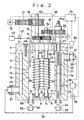
- Fig. 2 shows the bioreactor in a sectional view along the line A-A of Fig. 1 under omission of the substrate supplying device.
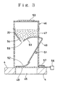
- Fig. 3 shows the substrate supplying device of the bioreactor in a sectional view along the line A-A of Fig. 1.
-
- In the bioreactor according to the present invention, the reaction vessel and components contacting with the reaction mixture may preferably be made of a material inert to the reaction mixture in both biological and chemical natures without exhibiting any toxicity to the microorganism and any catalytic poison to the reaction, such as a polytetrafluoroethylene or an acrylic resin.
- Any design may be applied to the screws, so long as a plurality of screws are arranged substantially in parallel and in an adjoining relationship to each other in such a manner that the contents of the reaction vessel is captured by two adjoining screws kept in rotation in between the confronting screw threads and is guided in the vertical direction in the reaction vessel. However, it is preferable that the two parallel screws each have a successive helical screw thread or fin turning in the opposing sense to each other and confronting each other and are disposed to permit their rotation in the reverse sense to each other, wherein it is especially preferable that the two screws have each a pitch nearly the same with each other. Here, the screws may be made of a material inert to the reaction environment and coupled together with rough-pitched screw thread or fin of reverse turning sense with each other, wherein the two screws are connected to a gearing disposed in an upper portion of the reaction vessel and are driven in a motion-coupled relation to effect rotation of these screws in the reverse sense to each other, to thereby cause the reaction vessel contents to be guided in vertical direction either upwards or downwards to reach an efficient agitation of the reaction mixture.
- For driving the screws, it is preferable to use a driving unit composed of a driving motor and a transmission mechanism for transmitting the driving power to the screws in reverse rotational sense through the gearing disposed above them.
- In the case that the plurality of screws are arranged in the reaction vessel at a close neighborhood of the inner wall surface of the reaction vessel and that a device for withdrawing the reaction mixture is arranged at a portion at which the reaction mixture is liberated from the screws, a sieved reaction product can be taken out of the bioreactor. For the device for excreting the reaction mixture, a screw conveyer may be adopted, while use of other pertinent apparatuses may of course be permitted.
- For the temperature conserving device for maintaining the reaction vessel at a predetermined temperature, an arrangement with a water jacket surrounding the reaction vessel through which water at a constant tempeature is circulated from a constant temperature bath may be preferable.
- For the device for supplying the reaction vessel with substrate, every voluntary one may be chosen in accordance with the mode of the reaction, while it is possible to employ such an embodiment in which the substrate is supplied from, for example, a hopper at a constant rate by dosing a predetermined amount of the substrate in each time interval.
- It is preferable to control the operations of the driving unit for the screws, the temperature preserving device, the substrate supplying device and the reaction product excreting device using a control unit including a computer.
- For conducting a biological or biochemical reaction using the bioreactor according to the present invention, the reaction vessel is supplied with a substrate while maintaining the reaction vessel at a predetermined temperature by operating the temperature conserving device and the reaction is carried out on the substrate in the presence of one or more microorganisms or one or more chemical substances, such as enzymes, under actuation of the driving unit for the screws. By the rotation of these screws, the contents of the reaction vesssel are guided vertically in the reaction vessel either upwards or downwards while being milled and sieved, to effect dispersion and mixing of the substrate. By selecting a narrower distance between the adjoining screws, the reaction mixture captured between the confronting screw theads or the helical fins will compressedly be forced towards the advancement of the rotating screws, whereby the solid particles of the substrate will be subjected to an action of attrition with each other and are thus milled mechanically.
- When the screws are arranged at a close neighborhood of the reaction vessel inner wall surface, a squeezing action is imparted to the reaction mixture on the side of the inner wall surface of the reaction vessel to thereby cause the smaller size particles formed by the milling action to come together, whereby a sieving of the solid particles are attained.
- The reaction vessel contents guided in the vertical direction are then deflected at the upper or lower portion of the vessel laterally and cause a convectional flow, whereby the substrate particles are dispersed and mixed uniformly. In this manner, reactions can be realized under a condition in which the substrate is dispersed and mixed uniformly, even if a uniform dispersion of the substrate is attainable only difficultly, such as in the case where the substrate is present as insoluble solid particles and tends to float up or sediment down in the reaction medium or in the case where it appears as a highly concentrated or highly viscous fluid. A part of the reaction mixture is excreted from the reaction vessel through the device for excreting the reaction mixture.
- The reaction can be conducted in accordance with a specific program set in the computer of the control unit and it is possible to conduct the reaction under a predetermined condition continuously for a long period of time. By controlling the agitation condition in the reaction vessel, it is possible to employ a mild agitation, whereby a reaction conducted while maintaining a feeble microorganism, such as a protozoa, may be realized.
- In the reactions, substrates having a floating or sedimenting nature may effectively be dispersed in the reaction medium, e.g. a culture medium, by an agitating effect due to the convectional flow and by the milling effect due to the compressive attrition of the particles. When the substrate is present as an insoluble solid particles, a mechanical milling of the substrate can be attained and the reaction can be conducted without incorporating a special pretreatment, such as an esterification for a substrate of low density oil or fat.
- If the reaction vessel is designed in a construction permitting maintenance of a gas-tight condition, a voluntary gas, such as an anaerobic gas, can be chosen to thereby enable to carry out a culture of, for example, an obligate anaerobic microorganism, easily.
- As described above, according to the bioreactor of the present invention, the substrate can effectively be milled to reach a uniform dispersion and mixing in the reaction medium and the reaction product can be withdrawn from the reaction vessel under separation by sieving, under a condition in which the substrate is dispersed and mixed uniformly, even if a uniform dispersion of the substrate is attainable only difficultly, such as in the case where the substrate is present as insoluble solid particles and tends to float up or sediment down in the reaction medium or in the case where it appears as a highly concentrated or highly viscous fluid, whereby a continuous operation of the bioreactor can be achieved under preservation of invariability of the reaction condition in the vessel for a long period of time.
- Below, the present invention is described by way of a preferred embodiment with reference to the appended Drawings. This embodiment illustrates a bioreactor adapted for a biological or biochemical reaction using a powder of cereal seeds (sesame, rice or the like) as the substrate.
- Fig. 1 is a plan view of the bioreactor, Fig. 2 is a sectional view thereof along the line A-A with its hopper being neglected and Fig. 3 shows the hopper in the section along the line A-A, wherein the plane of section is locally changed as indicated in Fig. 1 to help understanding.
- In Figs. 1 and 2, the
numeral 1 denotes the reaction vessel having acylindrical reaction chamber 2 surrounded by a double wall consisting of aninner wall 1a and anouter wall 1b constituting therebetween awater jacket 3. Thereaction vessel 1 is tightly closed by alid 4 fixed thereon withscrew bolts 5. Thereaction vessel 1 and thelid 4 are made of an inert material, such as an acrylic resin and are arranged in a gas-tight construction. Closely adjacent to theinner wall surface 2a of thereaction chamber 2, there are arranged twoscrews 6 and 7 in an upright posture, of whichshafts elements 8 and 9 on the bottom wall lc of the vessel and at their upper portions in bearingelements lid 4. Thescrews 6 and 7 are arranged in a closely adjoining relation to each other and have each ahelical fin portion 13 of the screws. Thescrews 6 and 7 are made of an inert material, such as polyacetal resin. - The
shafts screws 6 and 7 are provided each at the portion projecting above thelid 4 with atoothed wheel shaft 6a is further provided above thetoothed wheel 14 with atiming wheel 16 to be served for the transmission of the driving power from apulse motor 18 via atiming belt 17. Theshaft 7a is further provided above thetoothed wheel 15 with anothertoothed wheel 19. - Within the inner wall la is arranged at a portion in front of the nearest confronting
portion 13 of thescrews excretion path 21 for excreting the reaction product, communicating at its upper part to thereaction chamber 2 through a communicatingopening 22 and at its lower part to anexcretion line 23 via avalve 24. Theexcretion path 21 is provided therein with ascrew conveyer 25 of whichshaft 25a is rotatably supported at its upper portion in abearing element 27 in thelid 4. Theshaft 25a is provided at the portion projecting above thelid 4 with atoothed wheel 28 which is held in engagement with thetoothed wheel 19. - At a lower portion of the
outer wall 1b, aninlet 31 for a constant temperature water to thewater jacket 3 and, at an upper portion on the opposite side thereof, anexit 32 of thewater jacket 3 is disposed, respectively, both of which are connected to aconstant temperature bath 34 via acirculation line 33 and acirculation pump 35. Theconstant temperature bath 34 is controlled so as to maintain a constant temperature by the temperature signals from aheat sensor 39. A culturesolution supply line 36 opens into thereaction chamber 2 through thelid 4 to permit supply of the culture solution by afeed pump 37. Also agas supply line 41 connected to agas bomb 43 via acontrol valve 42 opens into thereaction chamber 2 to permit supply of the gas to thereaction mixture 40 in the chamber through thelid 4. - A
substrate supply inlet 45 is disposed near the center of thelid 4, above which asubstrate supply unit 46 is arranged. As shown in Fig. 3, thesubstrate supply unit 46 is provided with ashutter plate 48 at the bottom of itscasing 47 and with a swingingtype weighing device 49 arranged to permit swinging around theaxis 51 in its upper portion. The lower portion of the weighingdevice 49 is connected with theshutter plate 48 by aflexible connection member 52. Above the weighingdevice 49 is formed a movablearcuate hopper part 53 so as to function the operation of opening and closure of thepassage 55 between it and a fixedhopper part 54. Theshutter plate 48 serves for opening and closing the supply unit by actuating asolenoid 56 to retract the shutter plate and by deactivating it to restore into the closed position by acompression spring 57. 50 represents an inlet for replenishing the substrate. - As seen in Fig. 2, the
reaction vessel 1 is provided in its bottom 1c with anexhaustion path 58 communicating to anexhaustion line 59 via avalve 60. 10 denotes a control unit including a computer, an input unit, an output unit etc., which is connected electrically for controlling thepulse motor 18, theconstant temprature bath 34, thecirculation pump 35, thefeed pump 37, thecontrol valve 42, thesolenoid 56 and so on. - The biological or biochemical reaction using the bioreactor described above is realized in the following manner: The
constant temperature bath 34 is first adjusted to a predetermined temperature by a command from thecontrol unit 10, whereupon the water having the so-adjusted constant temperature is allowed to enter into thewater jacket 3 by actuating thecirculation pump 35 through thecirculation line 33 and thewater inlet 31 and is caused to circulate through them to maintain the temperature of the inside of thereaction chamber 2 at the corresponding constant temperature. Then, the culture solution (a buffer, a liquid culture medium or the like) is supplied to thereaction chamber 2 by actuating thefeed pump 37 by a command signal from thecontrol unit 10. In a similar manner, thecontrol valve 42 is actuated to supply thereaction chamber 2 with a gas (such as N2, CO2 or the like) from thegas bomb 43 via thegas supply line 41. - On the other hand, the
substrate supplying device 46 is operated by actuating thesolenoid 56 at a predetermined time interval by a command signal from thecontrol unit 10 to cause theshutter plate 48 to open and the weighingdevice 49 to swing open to effect dosage of the substrate, whereby thereaction chamber 2 is supplied with the substrate through thesubstrate supply inlet 45. Here, the weighingdevice 49 operates to close thepassage 55 by swinging the movable part around theaxis 51 to effect weighing of one dosage of thesubstrate 20, which is supplied to thereaction chamber 2 through thesupply inlet 45, whereupon theshutter plate 48 returns to the original position by the compression force of thespring 57, whereby thepassage 55 opens again to allow thesubstrate 20 to fall down on theshutter plate 48. - In the state described above, the
pulse motor 18 is actuated by a command signal from thecontrol unit 10 to cause thescrews 6 and 7 to rotate and the reaction is conducted in the presence of one or more microorganisms or one or more chamical substances such as enzymes. Here, the torque of thepulse motor 18 is transmitted to thetiming wheel 16 via thetiming belt 17, wherein the torque is further transmitted to theshaft 7a by thetoothed wheels shaft 6a. By this, thescrews 6 and 7 are caused to rotate in the opposing sense to each other, so that the reaction mixture existing at around them are guided in vertical direction whether upwards or downwards. - The
reaction mixture 40 existing in between the opposinghelical fins portion 13 of the twoscrews 6 and 7 is subjected to a compressive transportational action due to the narrow space restricted by thescrews 6 and 7 as well as due to the restriction of vertical movement of the reaction mixture by the presence of the fins, whereby a milling of the particles occurs due to an attritional effect between the particles with each other, resulting in a reduction of the particle size. Within the space surrounded by the screws and the inner wall surface la on the side of the communicatingopening 22, alifting flow path 2a is built up. In this area, small sized particles formed by the milling and passed through the confrontingportion 13 come together, whereby a sieving action occurs. All the reaction mixture portions lifted at around thescrews 6 and 7 including that flown up in thelifting flow path 2a are deflected into a horizontal flow at the upper end to thereby cause formation of a convectional flow so that the reaction mixture containing the substrate will be homogenized. - Even if the substrate is insoluble and tends to sediment down and even present in a high concentration, a uniform mixing thereof is attained by the rotation of the
screws 6 and 7. If the substrate tends to float up, it can be forced to flow down by rotating the screws in the reverse turn. - On rotating the
shaft 7a, thescrew conveyer 25 is rotated by the rotation of thetoothed wheels screws 6 and 7, whereby small-sized particles will come together in thelifting flow path 2a and a part of the reaction product flown up in thelifting flow path 2a enters theexcretion path 21 from the communicatingopening 22 and is forced to flow down and excreted from theexcretion line 23 by rotation of thescrew conveyer 25. The amount to be excreted from thepath 21 is adjusted by the revolution rate of thescrew conveyer 25 and the degree of opening of thevalve 24. Theexhaustion line 59 and thevalve 60 serve for exhausting the entire reaction mixture when the operation of the bioreactor is stopped. - The above-described bioreactor permits a voluntary selection of the revolution rate of the screws in the range from a mild rotation to a high speed rotation, by controlling the number of pulses supplied to the
pulse motor 18, wherein it is possible, therefore, to generate a large torque in a low speed operation for evading damages on the microorganism or the enzyme to promote the reaction. By the convective flow produced by thescrews 6 and 7, the substrate can effectively be dispersed in the culture medium regardless of the specific weight value by the convectional action caused by thescrews 6 and 7 and the internal mixing of the reaction mixture can efficiently be attained even for a highly viscous substance due to the permissible high torque. - In this manner, the bioreactor according to the present invention can afford to attain an effective dispersion of substrates which tend to float up or sediment down in the reaction mixture within the
reaction vessel 2, whereby maintenance of the uniformity of the reaction mixture can be realized by effecting agitation in the reaction vessel with a sufficient torque even in a highly viscous condition. By keeping the reaction vessel in a gas-tight condition, special gas phase systems, such as those to be incorporated in an aerobic or in an anaerobic reaction, can be selected for the reaction system. Due to the permission of a computer control of the condition of agitation of the reaction mixture, a wide range of reactions such as from a cell culture requiring a mild agitation to a biochemical reaction requiring vigorous agitation can be dealt with voluntarily with better reproducibility. Even for the substrate of insoluble solid, there is no need for converting the substrate into a soluble derivative, since the bioreactor according to the present invention provides a mechanical milling of the substrate with thescrews 6 and 7. - As experimental example, a biological reaction was carried out, in the presence of microorganisms existing in the ruminant stomach of a sheep under an anaerobic condition at 39 °C using unmilled rice grains as a substrate having higher specific gravity, on the one hand, and using sesame seeds as a substrate having lower specific gravity, on the other hand.
- For the case of rice grain, the
screws 6 and 7 were rotated so as to cause an upflow of the reaction mixture and, for the case of sesame seeds, thescrews 6 and 7 were rotated reversely, to carry out the biologcal reaction. In both the cases, the substrate was dispersed in the bioreactor and was taken up well by the microorganisms. In the case of sesame seeds, the reaction product was excreted downwards from the reaction vessel by using a reversing screw for thescrew conveyer 25. - In an ordinary shaking biological reaction using test tubes, both the rice grains and the sesame seeds were scarcely dispersed in the test tube and the rate of intake by the protozoa was low.
- While the above Example deals with a biological reaction of microorganisms with a substrate, it is able to apply the bioreactor according to the present invention also to other biological and biochemical reactions with high substrate concentrations, such as fermentation, waste water treatment and organic and inorganic biochemical reactions.
Claims (2)
- A bioreactor for realizing biological and/or biochemical reactions on substrates in the presence of microorganism(s) or chemical substance(s), comprisinga reactor vessel (1) for carrying out a reaction or reactions therein,a plurality of screws (6,7) arranged in the reaction vessel upright parallel and adjacent to one another and to the reaction vessel inner wall surface (2a) so as to build up a vertical flow path for a reaction product within the space surrounded by the screws and the inner wall surface, wherein the plurality of adjacent screws are so arranged that the helical screw thread of one screw is of opposite sense to that of an adjacent screw,means for rotating (14,15) adjacent screws in opposite senses of rotation to one another to thereby guide a reaction mixture in the reaction vessel upwards so as to cause mixing of the reaction mixture and a milling of the particles due to an attritional effect between the particles and so as to cause a sieving action by passing small sized particles into the vertical flow path through a confronting portion of adjacent screws,a means (35) for maintaining the reaction vessel at a predetermined temperature,a device (46) for supplying the reaction vessel with the substrate, anda device (58) for excreting the reaction mixture from the reaction vessel.
- A method for realizing biological and/or biochemical reactions in the presence of microorganism(s) or chemical substance(s), comprisingintroducing a substrate into a reaction vessel of a bioreactor containing one or more microorganisms or one or more chemical substances, said vessel being equipped with a plurality of screws arranged in the vessel upright, parallel and adjacent to one another and to the reaction vessel inner wall surface to build up a vertical flow path of a reaction product within the space surrounded by the screws and the inner wall surface, wherein said plurality of adjacent screws are so arranged that the helical screw thread of one screw is of opposite sense to that of an adjacent screw,conducting the reaction or reactions under operation of the bioreactor so as to rotate the adjacent screws in opposite sense of rotation to one another to thereby guide a reaction mixture in the reaction vessel upwards, so as to cause a mixing of the reaction mixture and a milling of the particles due to an attritional effect between the particles and so as to cause a sieving action by passing small sized particles into the vertical flow path through the confronting portion of adjacent screws, and excreting the reaction product from the vertical flow path.
Applications Claiming Priority (3)
| Application Number | Priority Date | Filing Date | Title |
|---|---|---|---|
| JP43316/95 | 1995-03-02 | ||
| JP04331695A JP3215862B2 (en) | 1995-03-02 | 1995-03-02 | Bioreactor and method of using the same |
| JP4331695 | 1995-03-02 |
Publications (2)
| Publication Number | Publication Date |
|---|---|
| EP0730025A1 EP0730025A1 (en) | 1996-09-04 |
| EP0730025B1 true EP0730025B1 (en) | 2001-05-30 |
Family
ID=12660410
Family Applications (1)
| Application Number | Title | Priority Date | Filing Date |
|---|---|---|---|
| EP95301717A Expired - Lifetime EP0730025B1 (en) | 1995-03-02 | 1995-03-15 | Bioreactor |
Country Status (4)
| Country | Link |
|---|---|
| US (1) | US5587298A (en) |
| EP (1) | EP0730025B1 (en) |
| JP (1) | JP3215862B2 (en) |
| DE (1) | DE69521114T2 (en) |
Families Citing this family (19)
| Publication number | Priority date | Publication date | Assignee | Title |
|---|---|---|---|---|
| JP3382928B2 (en) * | 1999-12-28 | 2003-03-04 | 彰 堀金 | Method and apparatus for manufacturing an organic processed product |
| DE60009434T2 (en) | 1999-12-28 | 2005-03-03 | Tsukuba Food Science, Inc., Ushiku | Method and device for producing a processed product from organic material |
| JP4179579B2 (en) | 2000-05-08 | 2008-11-12 | 東洋合成工業株式会社 | Method for producing 1,2-naphthoquinonediazide photosensitizer |
| US7326564B2 (en) | 2001-02-20 | 2008-02-05 | St. Jude Medical, Inc. | Flow system for medical device evaluation and production |
| US7635586B2 (en) | 2003-11-26 | 2009-12-22 | Broadley-James Corporation | Integrated bio-reactor monitor and control system |
| US7435581B2 (en) * | 2003-11-26 | 2008-10-14 | Broadley-James Corporation | Integrated bio-reactor monitor and control system |
| US20080032396A1 (en) * | 2006-08-02 | 2008-02-07 | Becton, Dickinson And Company | Bioreactor and Method |
| US9057044B2 (en) | 2006-08-30 | 2015-06-16 | Meir Israelowitz | Laminar flow reactor |
| DE102007007299B4 (en) * | 2007-02-07 | 2010-07-29 | Lipp Bio Plus Gmbh | Device for stirring the contents of a fermentation or digestion tank and fermentation or digester with such a device |
| WO2009042671A1 (en) * | 2007-09-24 | 2009-04-02 | The Board Of Trustees Of The University Of Illinois | Three-dimensional microfabricated bioreactors with embedded capillary network |
| JP5373497B2 (en) * | 2009-07-21 | 2013-12-18 | 日本分光株式会社 | Measuring device with temperature chamber control function |
| CN102125253B (en) * | 2010-11-29 | 2013-06-12 | 雀巢公司 | Method for preparing seasoner semifinished product and reactor device for implementing same |
| US9872448B2 (en) * | 2012-08-06 | 2018-01-23 | Council Of Scientific & Industrial Research | Bioreactor vessel for large scale growing of plants under aseptic condition |
| GB2527048B (en) * | 2014-06-09 | 2018-03-07 | Anaero Tech Ltd | Static batch reactor system |
| US10597623B2 (en) * | 2015-11-13 | 2020-03-24 | The Johns Hopkins University | Multiwell cell culture system having rotating shafts for mixing culture media and method of use thereof |
| DK3430119T3 (en) * | 2016-03-14 | 2023-09-18 | Omnibrx Biotechnologies Private Ltd | A BIOREACTOR SYSTEM AND ITS OPERATION |
| CN106267882B (en) * | 2016-08-30 | 2018-09-18 | 李斌 | A kind of microwave coupling leaching device |
| PL3712239T3 (en) * | 2019-03-22 | 2024-03-25 | BüHLER GMBH | EMPTYING THE RESIDUE |
| US12404496B2 (en) | 2019-06-28 | 2025-09-02 | Vanderbilt University | Bioreactor systems |
Family Cites Families (19)
| Publication number | Priority date | Publication date | Assignee | Title |
|---|---|---|---|---|
| NL8368C (en) * | ||||
| US1458492A (en) * | 1920-11-19 | 1923-06-12 | Paul L Mathews | Apparatus for mixing |
| DE909151C (en) * | 1950-05-28 | 1955-03-10 | Leistritz Maschfabrik Paul | Screw press |
| US3343922A (en) * | 1963-09-23 | 1967-09-26 | Vickers Zimmer Ag | Chemical reactor |
| JPS4823255B1 (en) * | 1970-04-27 | 1973-07-12 | ||
| GB1315741A (en) * | 1970-06-08 | 1973-05-02 | Du Pont Canada | Mixer |
| FR2218350B1 (en) * | 1973-02-16 | 1976-05-14 | Rhone Progil | |
| US4034967A (en) * | 1975-08-27 | 1977-07-12 | Gustairs John A | Mixer |
| IT1056974B (en) * | 1976-03-09 | 1982-02-20 | Nut Foods International Srl | STATIC MIXER APPARATUS |
| DE2638086A1 (en) * | 1976-08-24 | 1978-03-02 | Siemens Ag | INTEGRATED POWER SUPPLY |
| SU768447A1 (en) * | 1978-06-28 | 1980-10-07 | Московский Ордена Трудового Красного Знамени Институт Химического Машиностроения | Apparatus for ajitating loose and viscous materials |
| SU778765A1 (en) * | 1978-12-22 | 1980-11-15 | Предприятие П/Я М-5397 | Biplanetary mixer |
| SU803957A1 (en) * | 1979-04-23 | 1981-02-15 | Московский Ордена Трудового Красногознамени Институт Химическогомашиностроения | Mixer |
| JPS5832619A (en) * | 1981-08-19 | 1983-02-25 | Asahi Chem Ind Co Ltd | Preparation of polyoxymethylene |
| CS246370B1 (en) * | 1984-11-10 | 1986-10-16 | Miloslav Kolinsky | Method of vinyl polymers one-stage production and reactor for application of this method |
| JPS61264004A (en) * | 1985-05-17 | 1986-11-21 | Mitsubishi Heavy Ind Ltd | Surface-refreshing horizontal reactor |
| JPS63117038A (en) * | 1986-11-04 | 1988-05-21 | Hitachi Ltd | Horizontal reactor |
| DE4001986C1 (en) * | 1990-01-24 | 1991-09-19 | Hermann Berstorff Maschinenbau Gmbh, 3000 Hannover, De | |
| DD292437A5 (en) * | 1990-03-05 | 1991-08-01 | Veb Wasserversorgung Und Abwasserbehandlung Rostock,De | DEVICE FOR VENTILATION AND CONVERSION OF LIQUIDS |
-
1995
- 1995-03-02 JP JP04331695A patent/JP3215862B2/en not_active Expired - Lifetime
- 1995-03-15 DE DE69521114T patent/DE69521114T2/en not_active Expired - Fee Related
- 1995-03-15 EP EP95301717A patent/EP0730025B1/en not_active Expired - Lifetime
- 1995-03-24 US US08/409,446 patent/US5587298A/en not_active Expired - Fee Related
Also Published As
| Publication number | Publication date |
|---|---|
| JPH08228762A (en) | 1996-09-10 |
| DE69521114D1 (en) | 2001-07-05 |
| JP3215862B2 (en) | 2001-10-09 |
| DE69521114T2 (en) | 2001-09-13 |
| US5587298A (en) | 1996-12-24 |
| EP0730025A1 (en) | 1996-09-04 |
Similar Documents
| Publication | Publication Date | Title |
|---|---|---|
| US5587298A (en) | Bioreactor | |
| CA2653453A1 (en) | Conical screw blender | |
| JPH0365175A (en) | Bioreactor | |
| KR20210036509A (en) | Apparatus for processing food waste using multiple mixers and microorganism | |
| US5375783A (en) | Planetary grinding apparatus | |
| US3660244A (en) | Fermentation apparatus | |
| Dehkordi | Novel type of two‐impinging‐jets reactor for solid–liquid enzyme reactions | |
| CN220331650U (en) | High-speed masterbatch mixer | |
| JPS63194722A (en) | Apparatus for mixing heterogenous substance | |
| SU1666171A1 (en) | Reactor with multibank agitators for processing liquid mediums | |
| CN207699573U (en) | A kind of installation for fermenting | |
| JPS6422331A (en) | Dispersing device | |
| CN216677900U (en) | Combined mechanical stirrer | |
| KR20030034674A (en) | A vortexer for experimentation | |
| CN1174795C (en) | Ultrasonic oscillation bottle rolling device | |
| CN222900882U (en) | A agitated vessel for bio-pharmaceuticals | |
| CN224142242U (en) | A reaction vessel for chemical production | |
| CN224100624U (en) | A fructose processing auxiliary material addition device | |
| CN218307926U (en) | A agitating unit for enamel reactor | |
| JPS62183843A (en) | Dispersing stirrer | |
| JPH07136621A (en) | Garbage Disposal Processor | |
| JPH10323549A (en) | Stirrer for organic matter processing | |
| CN224172597U (en) | Device based on biological enzyme catalytic treatment contains phenol waste water | |
| CN216445332U (en) | Fermentation tank for cereal food puffing | |
| SU778765A1 (en) | Biplanetary mixer |
Legal Events
| Date | Code | Title | Description |
|---|---|---|---|
| PUAI | Public reference made under article 153(3) epc to a published international application that has entered the european phase |
Free format text: ORIGINAL CODE: 0009012 |
|
| AK | Designated contracting states |
Kind code of ref document: A1 Designated state(s): DE GB |
|
| 17P | Request for examination filed |
Effective date: 19970221 |
|
| 17Q | First examination report despatched |
Effective date: 20000315 |
|
| GRAG | Despatch of communication of intention to grant |
Free format text: ORIGINAL CODE: EPIDOS AGRA |
|
| GRAG | Despatch of communication of intention to grant |
Free format text: ORIGINAL CODE: EPIDOS AGRA |
|
| GRAH | Despatch of communication of intention to grant a patent |
Free format text: ORIGINAL CODE: EPIDOS IGRA |
|
| GRAH | Despatch of communication of intention to grant a patent |
Free format text: ORIGINAL CODE: EPIDOS IGRA |
|
| GRAA | (expected) grant |
Free format text: ORIGINAL CODE: 0009210 |
|
| AK | Designated contracting states |
Kind code of ref document: B1 Designated state(s): DE GB |
|
| REF | Corresponds to: |
Ref document number: 69521114 Country of ref document: DE Date of ref document: 20010705 |
|
| REG | Reference to a national code |
Ref country code: GB Ref legal event code: IF02 |
|
| PLBE | No opposition filed within time limit |
Free format text: ORIGINAL CODE: 0009261 |
|
| STAA | Information on the status of an ep patent application or granted ep patent |
Free format text: STATUS: NO OPPOSITION FILED WITHIN TIME LIMIT |
|
| 26N | No opposition filed | ||
| PGFP | Annual fee paid to national office [announced via postgrant information from national office to epo] |
Ref country code: GB Payment date: 20040310 Year of fee payment: 10 |
|
| PGFP | Annual fee paid to national office [announced via postgrant information from national office to epo] |
Ref country code: DE Payment date: 20040325 Year of fee payment: 10 |
|
| PG25 | Lapsed in a contracting state [announced via postgrant information from national office to epo] |
Ref country code: GB Free format text: LAPSE BECAUSE OF NON-PAYMENT OF DUE FEES Effective date: 20050315 |
|
| PG25 | Lapsed in a contracting state [announced via postgrant information from national office to epo] |
Ref country code: DE Free format text: LAPSE BECAUSE OF NON-PAYMENT OF DUE FEES Effective date: 20051001 |
|
| GBPC | Gb: european patent ceased through non-payment of renewal fee |
Effective date: 20050315 |