EP0729912B1 - Chain hoist with brake actuated clutch - Google Patents
Chain hoist with brake actuated clutch Download PDFInfo
- Publication number
- EP0729912B1 EP0729912B1 EP96103101A EP96103101A EP0729912B1 EP 0729912 B1 EP0729912 B1 EP 0729912B1 EP 96103101 A EP96103101 A EP 96103101A EP 96103101 A EP96103101 A EP 96103101A EP 0729912 B1 EP0729912 B1 EP 0729912B1
- Authority
- EP
- European Patent Office
- Prior art keywords
- clutch
- brake
- hoist according
- members
- rotationally fixed
- Prior art date
- Legal status (The legal status is an assumption and is not a legal conclusion. Google has not performed a legal analysis and makes no representation as to the accuracy of the status listed.)
- Expired - Lifetime
Links
Images


Classifications
-
- F—MECHANICAL ENGINEERING; LIGHTING; HEATING; WEAPONS; BLASTING
- F16—ENGINEERING ELEMENTS AND UNITS; GENERAL MEASURES FOR PRODUCING AND MAINTAINING EFFECTIVE FUNCTIONING OF MACHINES OR INSTALLATIONS; THERMAL INSULATION IN GENERAL
- F16D—COUPLINGS FOR TRANSMITTING ROTATION; CLUTCHES; BRAKES
- F16D67/00—Combinations of couplings and brakes; Combinations of clutches and brakes
- F16D67/02—Clutch-brake combinations
- F16D67/06—Clutch-brake combinations electromagnetically actuated
-
- B—PERFORMING OPERATIONS; TRANSPORTING
- B66—HOISTING; LIFTING; HAULING
- B66D—CAPSTANS; WINCHES; TACKLES, e.g. PULLEY BLOCKS; HOISTS
- B66D3/00—Portable or mobile lifting or hauling appliances
- B66D3/18—Power-operated hoists
- B66D3/20—Power-operated hoists with driving motor, e.g. electric motor, and drum or barrel contained in a common housing
- B66D3/22—Power-operated hoists with driving motor, e.g. electric motor, and drum or barrel contained in a common housing with variable-speed gearings between driving motor and drum or barrel
Definitions
- An electric chain hoist is described in DE-A-33 30 560.
- This electric chain hoist contains in one housing an induction motor provided with a cylindrical armature, a transmission input shaft via a slip clutch drives.
- the output shaft of the gearbox is non-rotatably coupled with the chain sprocket of the electric chain hoist.
- the brake acts through the Slip clutch through and can therefore be used for the chain generate no greater braking torque than the slip clutch allows maximum.
- it's stiction is greater than the sliding friction, it can happen that the hoist no longer has a load hanging on the hook can hold on even though the brake is engaged because the clutch slips.
- Such a situation can occur when the clutch first when lifting the load is operated in the field of static friction, then but due to a disturbance, for example a momentary one
- the load gets caught on an object or due to longitudinal vibrations in the chain, the torque limit of the Slip clutch is exceeded, which then in the Sliding friction passes.
- Even if the anchor stopped now is lowered and the holding brake is applied the load continues to decrease, because the slip clutch can be off the state of sliding friction may not return to the state of stiction.
- the braking torque can be independent of the slip torque of the slip clutch be adjusted and the hoist is thereby able to hold loads securely even when at Limit load conditions the slip clutch slipping has come.
- the brake acts on the new hoist Part of the powertrain that from the engine's perspective lies behind the slip clutch.
- the device which generates the brake bias, at the same time also acts on the slip clutch.
- This measure makes the brake the maximum slip torque the slip clutch increased.
- With appropriate dimensioning can be ensured that the slip clutch with the brake not released and the motor current switched on remains in the state of static friction and the tarnishing of the Motor blocked. If, based on this condition, the When the brake is released, the hoist runs with a slip clutch to who is still in the state of static friction located. So in a state in which they are can transmit greater torque.
- the timing of switching on the motor current and brake release is therefore relative not critical. You just need to keep the condition to release the brake only after the motor current was switched on. The response times of the brake need no longer considered in the new solution become. This time is subject to considerable specimen scatter and depends essentially on which one Overvoltage in a magnetically operated brake Brake magnet is excited. So fluctuate at otherwise constant Conditions the response times of the brake with the current one Mains voltage, what about the known solutions can lead to, depending on how high the mains voltage the hoist occasionally has a slipping clutch would start, while with the new solution that Always ensure that the clutch does not slip can be.
- Relationships can be reproduced very precisely reach if the braking surfaces are flat.
- Fig. 1 shows a highly schematic chain hoist 1 with a housing 2, in which an engine (Fig. 2) is arranged.
- a round link chain appears on an underside 5 from, at the lower end of a hook harness 6 is appropriate.
- the chain hoist 1 is attached by means of a hook 7 on a not shown stationary structure.
- this includes Engine an asynchronous motor 9 with a field winding 11, in its cylindrical bore 12 a cylindrical Squirrel-cage runner 13 is running. Furthermore, one belongs to the engine chain nut 14 recognizable only in section, on the a two-stage planetary gear from the side of the engine 9 15 is arranged. In addition to the two-stage Planetary gear 15 there is a combined clutch and braking device 16 in the drive train lies between the motor 9 and the chain sprocket 14. Through the Coupling device will powertrain in two Divided sections.
- the housing 2 of the chain hoist 1 consists of a Housing center piece 17 on its outer peripheral surface in the circumferential direction ribs 18 carries the Housing 2, seen in the transverse direction, an approximately rectangular Give contour. Because of the ribs 18, it has one over the Length continuous constant exterior shape while actually however, the actual body of the case in the is essentially tubular.
- the left end of the middle piece 17 is by means of a lid 19 closed, the complementary Centering shoulders 21 in the correct position on the center piece 17 is held.
- Connects to the right front end the middle piece 17 has the same outer contour shape Brake housing 22 in which the braking device 16 is housed.
- the brake housing 22 is also included corresponding cooling fins 23 provided in the circumferential direction lie.
- the end of the brake housing remote from the center piece 17 22 is closed with a further end cover 24, which essentially corresponds to the end cover 19 is mirror image.
- Both end covers 19 and 24 are on the same side over the side of the housing 2, resulting in an approx C-shaped side opening forms.
- a control housing 25 which is not illustrated terminals, contactors, electronic Controls and the like. Contains.
- the side protruding covers 19, 24 protect the control housing 25, which is usually made of a plastic, and balance the chain hoist 1 with respect to its longitudinal axis. If the weight of the lid 19, 24 is not sufficient additional weights in the lids 19, 24 attached become.
- a circular bore 26 into which the The laminated core of the stator 11 is shrunk in place with a friction fit is.
- the armature 13 is non-rotatably seated on a hollow shaft 27 at the left end using a deep groove ball bearing 28 is mounted in a cylindrical and to the bore 26 coaxial bearing bore 29 is seated.
- This hole 29 is in an inwardly facing tubular Extension 31 of the end cover 19.
- a deep groove ball bearing 32 available, the one with an adhesive seat in a bearing bore 33 plugged.
- the bearing bore 33 is in a Bore 26 protruding tubular extension 34, the a partition 35 formed in the center piece 17 protrudes.
- a further partition 36 whereby between the two partition walls 35 and 36 a chain sprocket housing 37 is divided.
- the chain sprocket 14 running therein is in one piece formed with a hollow shaft 38 on both sides the chain sprocket 14 in two deep groove ball bearings 39 and 41 is rotatably mounted.
- the two deep groove ball bearings 39 and 41 are in associated bearing bores 42 and 43.
- Die Bearing bore 42 is coaxial with the bearing bore 33 in the tubular extension 34 housed while the bearing bore 43 in a corresponding thickening of the partition 36 is housed.
- the diameter of the bearing bore 43 is chosen so that, based on Fig. 2 from the right forth both the deep groove ball bearing 39 and the chain sprocket 14 can be inserted because of the diameter of the bearing bore 43 is larger than the maximum diameter of the Chain sprocket 14.
- the the Chain sprocket 14 adjacent stage comprises three planet gears 46, the axes 47 of an associated planet carrier 48 are rotatably mounted and mesh with the ring gear 45.
- the Planet carrier 48 is by means of a profile toothing 49 rotatably with one to the right over the deep groove ball bearing 41 projecting stub of the hollow shaft 38 connected.
- the length of the Sun gear 51 is larger than the width of the planet gears 46 so that it projects to the right over the planet gears 46, if there is a washer 52 on the left adjacent end face of the shaft 38 starts.
- the protruding one Part of the sun gear 51 is complementary toothed bore 53 of a planet carrier 54 of the first stage of the two-stage planetary gear 15 its axes 55 in turn have a total of three planet gears 56, the associated sun gear 57 floating store that also protrudes to the right and into the Brake housing 22 protrudes.
- the gear connection between the engine 9 and the planetary gear 15 is done with the help of a plug or intermediate shaft 58, which is continuous on its outside is provided with a profile toothing.
- a plug or intermediate shaft 58 which is continuous on its outside is provided with a profile toothing.
- the end of the hollow shaft 27 of the armature 13 is located profile toothed section 61, to the profile toothing the stub shaft 58 is complementary. From here the Stub shaft 58 through the hollow shaft 27, through the hollow shaft 38 the chain sprocket 14, from there through the hollow sun gear 51 and through the sun gear 57 into the clutch and Brake unit 16.
- the stub shaft 58 At its left end on the engine side the stub shaft 58 through a in a corresponding groove seated snap ring 62, which is over a washer 63 supports the end face of the hollow shaft 27 in the direction axially secured to the right. Otherwise, the stub shaft 58 compared to the sun gear 51, the sun gear 57 and the Chain sprocket shaft 38 freely rotatable.
- the combined clutch and brake unit 16 has two parallel, flat and ring-shaped clutch plates 64 and 65 on that frictionally with each other are engaged, for which purpose, as shown, corresponding Wear friction linings.
- the two brake discs 64 or 65 which does not have a friction lining, is relatively strong educate to give her a large heat capacity so that the clutch grinds for a long time can without damaging the friction lining.
- the clutch disc 64 is the driven disc, which is why it is provided with a hub 66, which with the help one complementary to the profile teeth of the stub shaft 58 Profile teeth axially displaceable on the stub shaft, but is coupled to the stub shaft 58 in a rotationally fixed manner.
- the other clutch disc, clutch disc 65 is the clutch disc on the output or output side, which can be rotated loosely with respect to the stub shaft 58, for what purpose a bearing ring 67 is provided for the profile of the stub shaft 58 is.
- the clutch disc 65 is also provided with a hub 68 provided that an internal toothing corresponding to the external toothing of the sun gear 57 carries.
- the sun gear 57 is as shown, towards the clutch and brake unit 16 extended and stuck with this extended Section in the hub 68 of the clutch disc 65. On in this way it becomes axially displaceable but non-rotatable Connection between the clutch disc 65 and the Sun gear 57 manufactured.
- the bearing is carried out with the help of a ball bearing 69, that in a bore 71 of a partition 72 of the brake housing 22 sits.
- the hub is in this deep groove ball bearing 69 68 rotatably mounted.
- the bearing bore 71 for the ball bearing 69 is provided with an investment shoulder and also the hub 68 carries an abutment shoulder 73 so that one of right to left acting on the clutch disc 65 Axial force is introduced into the housing 2 via these shoulders can be.
- the two clutch plates 64 and 65 are simultaneously Brake discs, which is why they are on their outside pointing, i.e. surfaces pointing away from each other Brake pads 76 are provided, the diameter of which Diameters of the clutch linings of the clutch plates 64 or 65 matches. These brake pads 76 cooperate a stationary braking device 77 together.
- This stationary brake device 77 includes one in the brake housing 22 axially displaceable electromagnet 78 with a pot-shaped iron yoke 79 and one located therein Magnet winding 81.
- the iron yoke 79 is in the brake housing 22 secured against rotation with the help of in the housing contained guide grooves in which corresponding extensions of the Eisenjoch 79 are slidably received.
- the Eisenjoch 79 is arranged so that its open Side towards the two clutch plates 64 and 65 shows.
- the iron yoke 79 contains a through hole 82, through which the insertion shaft 58 protrudes.
- annular one Brake plate 83 In front of the opening of the iron yoke 79 is an annular one Brake plate 83 arranged using a compression spring 84 biased towards the clutch disc 64 is.
- This spring 84 in the form of a helical Compression spring is supported on an opposite one back shoulder of bore 82.
- Another annular brake plate 85 is located between the Clutch disc 65 and the partition 72. This brake disc is secured against rotation by means of several screws 86, however, axially slidably connected to the yoke 79.
- yoke 79 contains threaded bushes into which the Screws 86 are screwed in.
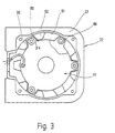
- Fig. 3 shows a front view of the Rear of brake unit 77.
- the brake housing 22 On its inside 91 Plurality of parallel to the axis of the stub shaft 58 extending ribs 92, each pair of grooves 93 limit.
- these grooves 93 are longitudinally displaceable Extensions 94 attached to the magnetic yoke 79, the Brake plate 83 and the brake plate 85 are provided.
- the brake unit 77 is secured against rotation in the brake housing 22 and can not be in one with a ventilated fair tilt to such an extent that uneven wear in the lower area of the brake plates 83 and 85 could come about.
- the chain sprocket 14 is inserted, which, as mentioned above, with its associated shaft 38 is in one piece, and the bearing 39 and 41. Then the planetary gear 15 installed and the brake housing 22nd put on. The prepared brake unit 16 can then to be fastened in the brake housing 22.
- the stub shaft 58 is from the engine side forth introduced until they the position shown in Fig. 2 occupies.
- the compression spring 74 is attached and with the help of the screwed nut 75 accordingly biased.
- front cover 24 can be put on, with which the mechanical assembly is done so far is.
- the stub shaft 58 is supported by the snap ring 72 on the hollow shaft 27 of the engine 9.
- the so on the hollow shaft 27th acting axial force is via the deep groove ball bearing 32 in initiated the housing centerpiece 17, the force on the partition 72 of the brake housing 22 transmits.
- At the Partition 72 is on the corresponding shoulder Ball bearing 69 to which the shoulder 73 of the hub 68 triggers.
- the power flow closes from the hub 68 the clutch disc 65 to the clutch disc 64 and from there via the hub 66 to the compression spring 74.
- the compression spring 84 generates the force with which two clutch plates 64 and 65 frictionally engaged stand when there is no additional pressure on the two clutch discs 64 and 65 acts.
- the pressure force caused by the spring 84 goes via the clutch disc 65 to the clutch disc 64 and from there to the brake plate 83, which is in the area supports its bore on the compression spring 84.
- the two clutch plates 64 and 65 are from the Brake plates 83 and 84 gripped like a pliers and by with a force corresponding to the outside the biasing force of the compression spring 84 compressed.
- At non-energized magnet 78 act on the two clutch plates 64 and 65 two springs, namely the Compression spring 74 and the compression spring 84.
- the Electromagnet 78 turned on, the effect of Compression spring 84 from the two clutch plates 64 and 65 taken away. These are then only in accordance with the Biasing force of the compression spring 74 in frictional engagement with one another biased.
- the new solution has the essential one Advantage that the braking torque with which the chain sprocket 14th can be braked, not by the slipping torque of the Safety clutch is dependent.
- both the input side as well as the clutch plate 64, 65 on the output side is each provided with its own brake pad 76, so that safe braking is guaranteed even then if the slip clutch itself fails to work would. Since both clutch discs 64 and 65 with one own friction brake pad 76 are provided by the associated brake plates 83 and 85 each clutch disc 64, 65 slowed down on their own, i.e. it becomes both the motor side as well, more importantly, the driven side and thus the chain sprocket side braked.
- the floating mounting of the brake unit 78 should ensure that both brake plates 83 and 85 in the same Can tighten and no bending forces on the occur both clutch discs 64 and 65.
Abstract
Description
In der DE-A-33 30 560 ist ein Elektrokettenzug beschrieben. Dieser Elektrokettenzug enthält in einem Gehäuse einen mit einem zylindrischen Anker versehenen Induktionsmotor, der über eine Rutschkupplung eine Getriebeeingangswelle antreibt. Die Ausgangswelle des Getriebes ist mit der Kettennuß des Elektrokettenzuges drehfest gekuppelt.An electric chain hoist is described in DE-A-33 30 560. This electric chain hoist contains in one housing an induction motor provided with a cylindrical armature, a transmission input shaft via a slip clutch drives. The output shaft of the gearbox is non-rotatably coupled with the chain sprocket of the electric chain hoist.
Auf der von der Getriebeeingangswelle abliegenden Seite des Ankers befindet sich eine Konusbremse, die durch Federmittel in die Bremsstellung vorgespannt ist. Zum Lüften der Bremse ist ein Tauchanker vorgesehen, der zu dem Motoranker koaxial ist und angezogen wird, wenn der Motor in Umdrehungen versetzt wird.On the one remote from the transmission input shaft There is a cone brake on the side of the armature that passes through Spring means is biased into the braking position. To the A brake anchor is provided to release the brake the motor armature is coaxial and is tightened when the Engine is rotated.
Aufgrund der Anordnung wirkt die Bremse durch die Rutschkupplung hindurch und kann folglich für die Kette kein größeres Bremsmoment erzeugen, als es die Rutschkupplung maximal zuläßt. Da für gewöhnlich die Haftreibung größer ist als die gleitende Reibung, kann es geschehen, daß das Hebezeug eine am Haken hängende Last nicht mehr festhalten kann, obwohl die Bremse eingerückt ist, weil die Kupplung durchrutscht. Eine solche Situation kann auftreten, wenn beim Anheben der Last die Kupplung zunächst im Bereich der Haftreibung betrieben wird, dann aber durch eine Störung, beispielsweise ein momentanes Verhaken der Last an einem Gegenstand oder durch Longitudinalschwingungen in der Kette, die Drehmomentgrenze der Rutschkupplung überschritten wird, die daraufhin in die Gleitreibung übergeht. Selbst wenn jetzt der Anker gestoppt wird und die Haltebremse zugespannt wird, senkt sich die Last weiter ab, denn die Rutschkupplung kann aus dem Zustand der gleitenden Reibung möglicherweise nicht mehr in den Zustand der Haftreibung zurückkehren.Due to the arrangement, the brake acts through the Slip clutch through and can therefore be used for the chain generate no greater braking torque than the slip clutch allows maximum. Usually it's stiction is greater than the sliding friction, it can happen that the hoist no longer has a load hanging on the hook can hold on even though the brake is engaged because the clutch slips. Such a situation can occur when the clutch first when lifting the load is operated in the field of static friction, then but due to a disturbance, for example a momentary one The load gets caught on an object or due to longitudinal vibrations in the chain, the torque limit of the Slip clutch is exceeded, which then in the Sliding friction passes. Even if the anchor stopped now is lowered and the holding brake is applied the load continues to decrease, because the slip clutch can be off the state of sliding friction may not return to the state of stiction.
Es ist deswegen zweckmäßig, die Bremse in jenen Teil des Antriebsstranges des Hebezeugs zu legen, der, vom Motor aus gesehen, hinter der Rutschkupplung liegt.It is therefore advisable to put the brakes on that part to lay the drive train of the hoist, which, from Seen engine, behind the slip clutch.
Eine solche Lösung ist beispielsweise aus der nicht vorveröffentlichten DE-A-44 08 578 bekannt. Das Bremsmoment kann unabhängig von dem Rutschmoment der Rutschkupplung eingestellt werden, und das Hebezeug ist dadurch in der Lage, Lasten sicher zu halten, selbst wenn bei Grenzlastbedingungen die Rutschkupplung ins Rutschen gekommen ist.Such a solution is not from, for example previously published DE-A-44 08 578 known. The braking torque can be independent of the slip torque of the slip clutch be adjusted and the hoist is thereby able to hold loads securely even when at Limit load conditions the slip clutch slipping has come.
Bei dieser Lösung muß allerdings die zeitliche Relation zwischen dem Anlaufen des Motors und dem Lüften der Bremse sehr exakt eingehalten werden. Würde beispielsweise die Bremse beim Anheben einer Last schneller geöffnet werden als der Motor anlaufen kann, würde sich zunächst die Last absenken, ehe sie vom Motor gehoben wird. Falls umgekehrt erst der Motor anläuft und dann die Bremse gelüftet wird, bringt die angezogene Bremse die Rutschkupplung zum Durchrutschen und es kann mit dem Hebezeug nur noch eine kleinere Last entsprechend dem Reibkoeffizient bei der gleitenden Reibung angehoben werden. With this solution, however, the temporal relation between starting the engine and venting the Brake are adhered to very precisely. For example, would the brake opens faster when lifting a load would be when the motor can start up first lower the load before lifting it from the engine. If conversely, first the motor starts and then the brake is released, the applied brake brings the slip clutch to slip through and it can with the hoist only a smaller load according to the coefficient of friction in the case of sliding friction.
Die Lösung nach der DE-A-37 10 332 vermeidet dieses Problem, indem ein Verschiebeankermotor verwendet wird, der die Synchronität zwischen Motor und Bremse zwangsläufig sicherstellt. Allerdings sind solche Verschiebeankermotoren mit konischem Anker sehr aufwendig in der Herstellung.The solution according to DE-A-37 10 332 avoids this Problem by using a sliding anchor motor the inevitably the synchronism between motor and brake ensures. However, such sliding armature motors are with conical anchor very elaborate in the Manufacturing.
Ausgehend hiervon ist es Aufgabe der Erfindung, ein Hebezeug zu schaffen, bei dem das Bremsmoment von dem eingestellten Rutschmoment der Rutschkupplung unabhängig ist und bei dem nicht die Gefahr besteht, daß die Bremse die Rutschkupplung zum Gleiten bringt.Based on this, it is an object of the invention to To create a hoist in which the braking torque of the set slip torque of the slip clutch independently is and at which there is no risk that the brake makes the slip clutch slide.
Diese Aufgabe wird erfindungsgemäß durch das Hebezeug
mit den Merkmalen des Anspruches 1 gelöst.This object is achieved by the hoist
solved with the features of
Die Bremse wirkt bei dem neuen Hebezeug auf jenen Teil des Antriebsstrangs, der aus der Sicht des Motors hinter der Rutschkupplung liegt. Durch entsprechende konstruktive Gestaltung ist dafür gesorgt, daß die Vorrichtung, die die Bremsvorspannung erzeugt, gleichzeitig auch auf die Rutschkupplung einwirkt. Bei nicht gelüfteter Bremse wird durch diese Maßnahme das maximale Rutschmoment der Rutschkuplung erhöht. Bei entsprechender Dimensionierung kann sichergestellt werden, daß die Rutschkupplung bei nicht gelüfteter Bremse und eingeschaltetem Motorstrom im Zustand der Haftreibung bleibt und das Anlaufen des Motors blockiert. Wenn, ausgehend von diesem Zustand, die Bremse gelüftet wird, läuft das Hebezeug mit einer Rutschkupplung an, die sich nach wie vor im Zustand der Haftreibung befindet. Also in einem Zustand, in dem sie das größere Drehmoment übertragen kann.The brake acts on the new hoist Part of the powertrain that from the engine's perspective lies behind the slip clutch. By appropriate constructive design ensures that the device, which generates the brake bias, at the same time also acts on the slip clutch. When not ventilated This measure makes the brake the maximum slip torque the slip clutch increased. With appropriate dimensioning can be ensured that the slip clutch with the brake not released and the motor current switched on remains in the state of static friction and the tarnishing of the Motor blocked. If, based on this condition, the When the brake is released, the hoist runs with a slip clutch to who is still in the state of static friction located. So in a state in which they are can transmit greater torque.
Die zeitliche Steuerung des Einschaltens des Motorstroms und des Lüftens der Bremse ist folglich relativ unkritisch. Es braucht nur die Bedingung eingehalten zu werden, die Bremse erst zu lüften, nachdem der Motorstrom eingeschaltet wurde. Die Ansprechzeiten der Bremse brauchen bei der neuen Lösung nicht mehr berücksichtigt zu werden. Gerade diese Zeit unterliegt beträchtlichen Exemplarstreuungen und hängt wesentlich davon ab, mit welcher Überspannung bei einer magnetisch betätigten Bremse der Bremsmagnet erregt wird. So schwanken bei sonst konstanten Bedingungen die Ansprechzeiten der Bremse mit der momentanen Netzspannung, was bei den bekannten Lösungen dazu führen kann, daß, je nachdem, wie hoch die Netzspannung ist, das Hebezeug gelegentlich mit durchrutschender Kupplung anlaufen würde, während bei der neuen Lösung das Anlaufen mit nicht durchrutschender Kupplung immer sichergestellt werden kann.The timing of switching on the motor current and brake release is therefore relative not critical. You just need to keep the condition to release the brake only after the motor current was switched on. The response times of the brake need no longer considered in the new solution become. This time is subject to considerable specimen scatter and depends essentially on which one Overvoltage in a magnetically operated brake Brake magnet is excited. So fluctuate at otherwise constant Conditions the response times of the brake with the current one Mains voltage, what about the known solutions can lead to, depending on how high the mains voltage the hoist occasionally has a slipping clutch would start, while with the new solution that Always ensure that the clutch does not slip can be.
Konstruktiv sehr einfach werden die Verhältnisse, wenn die Rutschkupplung aus der Sicht der Bremse als zweiteilige Bremsscheibe ausgebildet ist, so daß sich die Anpreßkraft der Kupplungsscheiben automatisch erhöht, wenn die Bremse zugespannt ist. Eine solche Anordnung läßt sich erreichen, wenn das wenigstens eine ausgangsseitige Kupplungsglied gleichzeitig das wenigstens eine drehbare Bremsglied ist oder mit diesem drehfest gekuppelt ist.The construction becomes very simple, if the slip clutch from the perspective of the brake than two-piece brake disc is designed so that the Clutch disc contact pressure increases automatically when the brake is applied. Such an arrangement can be achieve when the at least one output-side coupling member at the same time the at least one rotatable Brake member is or is rotatably coupled with this.
Sehr genau reproduzierbare Verhältnisse lassen sich erreichen, wenn die Bremsflächen Planflächen sind.Relationships can be reproduced very precisely reach if the braking surfaces are flat.
Ein vorzeitiger Verschleiß der Reibflächen einerseits und eine komplizierte Montage andererseits lassen sich vermeiden, wenn entweder die Kupplungseinrichtung oder die Bremseinrichtung axial schwimmend, aber im übrigen kippfrei gelagert sind. Beim Zuspannen der Bremse kann sich bei einer schwimmenden Lagerung der Kupplungseinrichtung diese axial entsprechend zwischen den Bremsflächen zentrieren, oder umgekehrt, bei einer axial festgelegten Kupplungseinrichtung kann sich die gesamte Bremseinrichtung entsprechend axial verschieben. Bei geöffneter Bremse wird durch die kippfreie schwimmende Lagerung ein Streifen einzelner Teile der Reibflächen vermieden. On the one hand, premature wear of the friction surfaces and a complicated assembly on the other hand avoid if either the coupling device or the Brake device floating axially, but otherwise free of tipping are stored. When the brake is applied, the with a floating bearing of the coupling device center them axially between the braking surfaces, or vice versa, at an axially fixed Coupling device can be the entire braking device move axially accordingly. With the brake open becomes a streak due to the tilt-free floating storage individual parts of the friction surfaces avoided.
Im übrigen sind Weiterbildungen der Erfindung Gegenstand von Unteransprüchen.In addition, developments of the invention are the subject of subclaims.
In der Zeichnung sind Ausführungsbeispiele des Gegenstandes
der Erfindung dargestellt. Es zeigen:
Fig. 1 zeigt stark schematisiert einen Kettenzug
1 mit einem Gehäuse 2, in dem ein Triebwerk (Fig. 2)
angeordnet ist. An einer Unterseite tritt eine Rundgliederkette
5 aus, an deren unterem Ende ein Hakengeschirr 6
angebracht ist. Die Befestigung des Kettenzuges 1 geschieht
mittels eines Hakens 7 an einer nicht gezeigten
ortsfesten Struktur.Fig. 1 shows a highly
Wie der Schnitt nach Fig. 2 erkennen läßt, umfaßt das
Triebwerk einen Asynchronmotor 9 mit einer Feldwicklung
11, in deren zylindrischer Bohrung 12 ein zylindrischer
Käfigläufer 13 läuft. Ferner gehört zu dem Triebwerk eine
lediglich im Schnitt erkennbare Kettennuß 14, auf deren
von dem Motor 9 abliegenden Seite ein zweistufiges Planetengetriebe
15 angeordnet ist. Neben dem zweistufigen
Planetengetriebe 15 befindet sich eine kombinierte Kupplungs-
und Bremseinrichtung 16, die im Antriebsstrang
zwischen dem Motor 9 und der Kettennuß 14 liegt. Durch die
Kupplungseinrichtung wird der Antriebsstrang in zwei
Abschnitte aufgeteilt.As can be seen from the section of FIG. 2, this includes
Engine an
Das Gehäuse 2 des Kettenzugs 1 besteht aus einem
Gehäusemittelstück 17, das auf seiner Außenumfangsfläche
in Umfangsrichtung verlaufende Rippen 18 trägt, die dem
Gehäuse 2, in Querrichtung gesehen, eine etwa rechteckige
Kontur verleihen. Wegen der Rippen 18 hat es eine über die
Länge durchlaufende konstante Außengestalt, während tatsächlich
jedoch der eigentliche Körper des Gehäuses im
wesentlichen rohrförmig ist.The
Das linke Stirnende des Mittelstücks 17 ist mittels
eines Deckels 19 verschlossen, der über komplementäre
Zentrierschultern 21 lagerichtig auf dem Mittelstück 17
gehalten ist. An dem rechten Stirnende schließt sich an
das Mittelstück 17 ein dieselbe Außenumrißgestalt aufweisendes
Bremsgehäuse 22 an, in dem die Bremseinrichtung
16 untergebracht ist. Auch das Bremsgehäuse 22 ist mit
entsprechenden Kühlrippen 23 versehen, die in Umfangsrichtung
liegen.The left end of the
Das von dem Mittelstück 17 abliegende Ende des Bremsgehäuses
22 ist mit einem weiteren Stirndeckel 24 verschlossen,
der im wesentlichen zu dem Stirndeckel 19
spiegelbildlich ist.The end of the brake housing remote from the
Beide Stirndeckel 19 und 24 stehen zur gleichen Seite
über das Gehäuse 2 seitlich über, wodurch sich eine etwa
C-förmige seitliche Öffnung bildet. In dieser seitlichen
Öffnung ist ein Steuergehäuse 25 untergebracht, das nicht
veranschaulichte Anschlußklemmen, Schaltschütze, elektronische
Steuerungen und dergl. enthält. Die seitlichen
überstehenden Deckel 19, 24 schützen das Steuergehäuse 25,
das üblicherweise aus einem Kunststoff besteht, und balancieren
den Kettenzug 1 bezüglich seiner Längsachse. Falls
das Gewicht der Deckel 19, 24 nicht ausreicht, können
zusätzliche Gewichte in den Deckeln 19, 24 angebracht
werden.Both end covers 19 and 24 are on the same side
over the side of the
Ausgehend von dem Stirndeckel 19 führt in das Mittelstück
17 eine kreisförmige Bohrung 26 hinein, in der das
Blechpaket des Stators 11 reibschlüssig festsitzend eingeschrumpft
ist. Der Anker 13 sitzt drehfest auf einer Hohlwelle
27, die am linken Ende mit Hilfe eines Rillenkugellagers
28 gelagert ist, das in einer zylindrischen und zu
der Bohrung 26 koaxialen Lagerbohrung 29 sitzt. Diese Bohrung
29 befindet sich in einem nach innen weisenden rohrförmigen
Fortsatz 31 des Stirndeckels 19. Zur Lagerung des
anderen Endes der Hohlwelle 27 ist ein Rillenkugellager 32
vorhanden, das mit Haftsitz in einer Lagerbohrung 33
steckt. Die Lagerbohrung 33 befindet sich in einem in die
Bohrung 26 ragenden rohrförmigen Fortsatz 34, der aus
einer in dem Mittelstück 17 eingeformten Trennwand 35
vorsteht.Starting from the
Im Abstand zu der Trennwand 35 enthält das Mittelstück
17 eine weitere Trennwand 36, wodurch zwischen den
beiden Trennwänden 35 und 36 ein Kettennußgehäuse 37
abgeteilt ist. Die darin laufende Kettennuß 14 ist einstückig
mit einer Hohlwelle 38 ausgebildet, die beidseits
der Kettennuß 14 in zwei Rillenkugellagern 39 und 41
drehbar gelagert ist. Die beiden Rillenkugellager 39 und
41 stecken in zugehörigen Lagerbohrungen 42 und 43. Die
Lagerbohrung 42 ist koaxial zu der Lagerbohrung 33 in dem
rohrförmigen Fortsatz 34 untergebracht, während die Lagerbohrung
43 in einer entsprechenden Verdickung der Trennwand
36 untergebracht ist. Der Durchmesser der Lagerbohrung
43 ist so gewählt, daß, bezogen auf Fig. 2 von rechts
her sowohl das Rillenkugellager 39 als auch die Kettennuß
14 eingeführt werden können, da der Durchmesser der Lagerbohrung
43 größer ist als der maximale Durchmesser der
Kettennuß 14.At a distance from the
Rechts von der Trennwand 36 erweitert sich der Innenraum
des Gehäuses 2 und es befindet sich dort eine zu den
Lagerbohrungen 42 und 43 koaxiale Bohrung 44, in die ein
Hohlrad 45 eingeschrumpft ist, das für beide Stufen des
zweistufigen Planetengetriebes 15 gemeinsam ist. Die der
Kettennuß 14 benachbarte Stufe umfaßt drei Planetenräder
46, die auf Achsen 47 eines zugehörigen Planetenträgers 48
drehbar gelagert sind und mit dem Hohlrad 45 kämmen. Der
Planetenträger 48 ist mit Hilfe einer Profilverzahnung 49
drehfest mit einem nach rechts über das Rillenkugellager
41 überstehenden Stummel der Hohlwelle 38 verbunden.The interior widens to the right of the
Mit Hilfe der drei Planetenräder 46 der zweiten Stufe
ist deren Sonnenrad 51 schwimmend gelagert. Die Länge des
Sonnenrades 51 ist größer als die Breite der Planetenräder
46, so daß es nach rechts über die Planetenräder 46 vorragt,
wenn es links über eine Zwischenscheibe 52 an der
benachbarten Stirnseite der Welle 38 anläuft. Der überstehende
Teil des Sonnenrades 51 steckt in einer komplementär
verzahnten Bohrung 53 eines Planetenträgers 54 der
ersten Stufe des zweistufigen Planetengetriebes 15. Auf
dessen Achsen 55 sitzen wiederum insgesamt drei Planetenräder
56, die ein zugehöriges Sonnenrad 57 schwimmend
lagern, das ebenfalls nach rechts übersteht und in das
Bremsgehäuse 22 ragt.With the help of the three
Die getriebliche Verbindung zwischen dem Motor 9 und
dem Planetengetriebe 15 geschieht mit Hilfe einer Steck-
oder Zwischenwelle 58, die an ihrer Außenseite durchgehend
mit einer Profilverzahnung versehen ist. In dem linken
Ende der Hohlwelle 27 des Ankers 13 befindet sich ein
profilverzahnter Abschnitt 61, der zu der Profilverzahnung
der Steckwelle 58 komplementär ist. Von hier aus führt die
Steckwelle 58 durch die Hohlwelle 27, durch die Hohlwelle
38 der Kettennuß 14, von dort durch das hohle Sonnenrad 51
und durch das Sonnenrad 57 bis in die Kupplungs- und
Bremseinheit 16. An ihrem linken motorseitigen Ende ist
die Steckwelle 58 durch einen in einer entsprechenden Nut
sitzenden Sprengring 62, der sich über eine Beilagscheibe
63 der Stirnseite der Hohlwelle 27 abstützt, in Richtung
nach rechts axial gesichert. Im übrigen ist die Steckwelle
58 gegenüber dem Sonnenrad 51 dem Sonnenrad 57 und der
Kettennußwelle 38 frei drehbar.The gear connection between the
Die kombinierte Kupplungs- und Bremseinheit 16 weist
zwei zueinander parallele, plane und ringförmige Kupplungsscheiben
64 und 65 auf, die reibschlüssig miteinander
in Eingriff stehen, wozu sie, wie dargestellt, entsprechende
Reibbeläge tragen. Aus wärmetechnischen Gründen ist
es zweckmäßig, diejenige der beiden Bremsscheiben 64 oder
65, die keinen Reibbelag trägt, verhältnismäßig stark
auszubilden, um ihr eine große Wärmekapazität zu geben,
damit die Kupplung die vorgeschrieben lange Zeit schleifen
kann, ohne daß der Reibbelag beschädigt wird. An Stelle
der gezeigten planen Gestalt der Kupplungscheiben 64 und
65 können sie auch konusförmige Reibflächen tragen.The combined clutch and
Die Kupplungsscheibe 64 ist die angetriebene Scheibe,
weshalb sie mit einer Nabe 66 versehen ist, die mit Hilfe
einer zu der Profilverzahnung der Steckwelle 58 komplementären
Profilverzahnung auf der Steckwelle axial verschieblich,
jedoch mit der Steckwelle 58 drehfest gekuppelt ist.
Die andere Kupplungsscheibe, die Kupplungsscheibe 65, ist
die ausgangsseitige oder abtriebsseitige Kupplungsscheibe,
die gegenüber der Steckwelle 58 lose drehbar ist, wozu auf
dem Profil der Steckwelle 58 ein Lagerring 67 vorgesehen
ist. Auch die Kupplungsscheibe 65 ist mit einer Nabe 68
versehen, die eine Innenverzahnung entsprechend der Außenverzahnung
des Sonnenrades 57 trägt. Das Sonnenrad 57 ist,
wie dargestellt, in Richtung auf die Kupplungs- und Bremseinheit
16 verlängert und steckt mit diesem verlängerten
Abschnitt in der Nabe 68 der Kupplungsscheibe 65. Auf
diese Weise wird eine axial verschiebliche, jedoch drehfeste
Verbindung zwischen der Kupplungsscheibe 65 und dem
Sonnenrad 57 hergestellt.The clutch disc 64 is the driven disc,
which is why it is provided with a
Die Lagerung erfolgt mit Hilfe eines Kugellagers 69,
das in einer Bohrung 71 einer Trennwand 72 des Bremsgehäuses
22 sitzt. In diesem Rillenkugellager 69 ist die Nabe
68 drehbar gelagert. Die Lagerbohrung 71 für das Kugellager
69 ist mit einer Anlageschulter versehen und auch
die Nabe 68 trägt eine Anlageschulter 73, so daß eine von
rechts nach links auf die Kupplungsscheibe 65 wirkende
Axialkraft über diese Schultern in das Gehäuse 2 eingeleitet
werden kann.The bearing is carried out with the help of a
Um die Vorspannung zu erzeugen, mit der die beiden
Kupplungsscheiben 64 und 65 in Reibeingriff vorgespannt
sind, sitzt auf einem nach rechts über die Kupplungsscheibe
64 vorstehenden Abschnitt der Steckwelle 58 eine als
Druckfeder wirkende Schraubenfeder 74, die mittels einer
auf ein entsprechendes Gewinde der Steckwelle 58 aufgedrehte
Mutter 75 vorzuspannen ist. Gegebenenfalls liegen
zwischen der Mutter 75 und der Feder 74 einerseits bzw.
zwischen der Feder 74 und der Nabe 66 der Kupplungsscheibe
64 andererseits Beilagscheiben, die in der Zeichnung
veranschaulicht sind, jedoch kein Bezugszeichen tragen. To create the preload with which the two
Die beiden Kupplungsscheiben 64 und 65 sind gleichzeitig
Bremsscheiben, weshalb sie auf ihren nach außen
weisenden, d.h. voneinander weg zeigenden Flächen mit
Bremsbelägen 76 versehen sind, deren Durchmesser mit den
Durchmessern der Kupplungsbeläge der Kupplungsscheiben 64
oder 65 übereinstimmt. Diese Bremsbeläge 76 wirken mit
einer stationären Bremseinrichtung 77 zusammen. Diese
stationäre Bremseinrichtung 77 umfaßt einen in dem Bremsgehäuse
22 axial verschieblichen Elektromagneten 78 mit
einem topfförmigen Eisenjoch 79 und einer darin befindlichen
Magnetwicklung 81. Das Eisenjoch 79 ist in dem Bremsgehäuse
22 drehgesichert mit Hilfe von in dem Gehäuse
enthaltenen Führungsnuten, in denen entsprechende Fortsätze
des Eisenjochs 79 gleitend aufgenommen sind.The two
Das Eisenjoch 79 ist so angeordnet, daß seine offene
Seite in Richtung auf die beiden Kupplungsscheiben 64 und
65 zeigt. Außerdem enthält das Eisenjoch 79 eine Durchgangsbohrung
82, durch die die Einsteckwelle 58 hindurchragt.The
Vor der Öffnung des Eisenjoches 79 ist eine ringförmige
Bremsplatte 83 angeordnet, die mit Hilfe einer Druckfeder
84 in Richtung auf die Kupplungsscheibe 64 zu vorgespannt
ist. Diese Feder 84 in Form einer schraubenförmigen
Druckfeder stützt sich an einer gegenüberliegenden
rückwärtigen Schulter der Bohrung 82 ab. Eine weitere
ringförmige Bremsplatte 85 befindet sich zwischen der
Kupplungsscheibe 65 und der Trennwand 72. Diese Bremsscheibe
ist mit Hilfe mehrerer Schrauben 86 drehgesichert,
jedoch axial verschieblich mit dem Joch 79 verbunden. Das
Joch 79 enthält zu diesem Zweck Gewindebuchsen, in die die
Schrauben 86 eingedreht sind.In front of the opening of the
Fig. 3 zeigt schließlich eine Stirnansicht auf die
Rückseite des Bremseinheit 77. Wie dort zu erkennen ist
trägt das Bremsgehäuse 22 auf seiner Innenseite 91 eine
Vielzahl von parallel zu der Achse der Steckwelle 58
verlaufenden Rippen 92, die jeweils paarweise Nuten 93
begrenzen. In diesen Nuten 93 befinden sich längsverschieblich
Fortsätze 94, die an dem Magnetjoch 79, der
Bremsplatte 83 und der Bremsplatte 85 vorgesehen sind.
Durch Zusammenwirken dieser Fortsätze 94 mit den Nuten 93
ist die Bremseinheit 77 in dem Bremsgehäuse 22 drehgesichert
und kann bei gelüfteter Bemse auch nicht in einem
solchen Maße kippen, als daß ein ungleichmäßiger Verschleiß
im unteren Bereich der Bremsplatten 83 und 85
zustandekommen könnte.Fig. 3 shows a front view of the
Rear of
Die Montage des insoweit beschriebenen Kettenzugs 1 geschieht wie folgt:The assembly of the chain hoist 1 described so far happens as follows:
An dem Gußrohling werden zunächst die Bohrungen 26,
44 sowie die Lagerbohrungen 33, 42 und 43 koaxial zueinander
fertig bearbeitet, einschließlich der Schulter 21,
auf der später der Lagerdeckel 19 sitzt. Sodann werden der
Stator 11 und das Hohlrad 45 in die zugehörigen Bohrungen
26 bzw. 44 des Mittelstücks 17 eingeschrumpft.At first, the
Nachdem dies geschehen ist, werden das Lager 32 und
sodann der Anker 13 mit seiner Hohlwelle 27 eingesetzt.
Daraufhin wird der Lagerdeckel 19 mit dem darin sitzenden
Lager 29 auf dem Gehäusemittelstück 17 befestigt.After this is done, the
Als nächstes erfolgt das Einsetzen der Kettennuß 14,
die, wie oben erwähnt, mit ihrer zugehörigen Welle 38
einstückig ist, und der Lager 39 und 41. Anschließend wird
das Planetengetriebe 15 eingebaut und das Bremsgehäuse 22
aufgesetzt. Sodann kann die vorbereitete Bremseinheit 16
in dem Bremsgehäuse 22 befestigt werden.Next, the
Parallel zu der vorstehend beschriebenen Montage
erfolgt der Zusammenbau der kombinierten Kupplungs- und
Bremseinheit 16. Dies geschieht, indem nach dem Einsetzen
der Druckfeder 84 auf das Magnetjoch 79 die Bremsplatte
83, die Kupplungsscheibe 64, die Kupplungsscheibe 65 und
schließlich die Bremsplatte 85 mit der dargestellten
Orientierung aufgelegt werden. Sodann werden werden die
Schrauben 86 in das Magnetjoch 79 eingedreht. Das Eindrehen
der Schrauben 86 geschieht solange, bis zwischen
der betreffenden Stirnseite des Magnetjochs 79 und der
unmittelbar benachbarten Bremsplatte 83 der gewünschte
Luftspalt erreicht ist, der später bei gelüfteter Bremse
den Lüftespalt definiert. Die so vorbereitete Kupplungs-
und Bremseinheit 16 wird mit der Nabe 68 voraus in das
Kugellager 69 eingesteckt, wobei gleichzeitig das Sonnenrad
57 mit seinem vorstehenden Abschnitt in die Nabe 68
eindringt.Parallel to the assembly described above
the combined clutch and
Als letztes wird die Steckwelle 58 von der Motorseite
her eingeführt, bis sie die in der Fig. 2 gezeigte Lage
einnimmt. Auf den in der Bohrung 82 des Magnetjochs 79
befindlichen Abschnitt wird die Druckfeder 74 aufgesteckt
und mit Hilfe der aufgeschraubten Mutter 75 entsprechend
vorgespannt.Finally, the
Als letztes kann der Stirndeckel 24 aufgesetzt werden,
womit der mechanische Zusammenbau insoweit erledigt
ist.Finally, the
Die Funktionsweise des beschriebenen Kettenzugs,
insbesondere der kombinierten Brems- und Kupplungseinheit
16, ist wie folgt:The operation of the chain hoist described,
especially the combined brake and
Der Kraftfluß, der zum Vorspannen der beiden Kupplungsscheiben
64 und 65 in Reibeingriff miteinander dient,
geht, ausgehend von der Druckfeder 74 zu der Mutter 75,
die die Kraft in die Steckwelle 58 einleitet. Die Steckwelle
58 stützt sich über den Sprengring 72 an der Hohlwelle
27 des Motors 9 ab. Die so auf die Hohlwelle 27
wirkende Axialkraft wird über das Rillenkugellager 32 in
das Gehäusemittelstück 17 eingeleitet, das die Kraft auf
die Trennwand 72 des Bremsgehäuses 22 überträgt. An der
Trennwand 72 liegt an der entsprechenden Schulter das
Kugellager 69 an, an das die Schulter 73 der Nabe 68
anstößt. Der Kraftfluß schließt sich von der Nabe 68 über
die Kupplungsscheibe 65 zu der Kupplungsscheibe 64 und von
dort über deren Nabe 66 zu der Druckfeder 74. Somit wird
mit Hilfe der Druckfeder 84 die Kraft erzeugt, mit der die
beiden Kupplungsscheiben 64 und 65 reibschlüssig in Eingriff
stehen, wenn keine zusätzliche Druckkraft auf die
beiden Kupplungsscheiben 64 und 65 einwirkt.The flow of force used to pretension the two
Eine solche zusätzliche Kraft erzeugt bei dem neuen
Kettenzug die Druckfeder 84 der Bremseinrichtung 78. Wie
die Figur erkennen läßt, sitzen die beiden Kupplungsscheiben
64 und 65 zwischen den beiden ringförmigen Bremsscheiben
83 und 85. Diese beiden Bremsplatten 83 und 85 werden
mit Hilfe der Druckfeder 84 aufeinander zu vorgespannt.
Der Kraftfluß dieser Druckfeder 84 wird am rechten Ende
der Bohrung 82 über eine gezeigte, jedoch nicht mit einem
Bezugszeichen versehene Ringschulter in das Magnetjoch 79
eingeleitet. Die Kraft der Druckfeder 84 geht durch die
Schrauben 86 und über deren Kopf zu der linken Bremsplatte
85. Die Bremsplatte 85 liegt ringförmig an dem Bremsbelag
76 der Kupplungsscheibe 65 an.Such an additional force creates in the new
Chain hoist the
Die von der Feder 84 hervorgerufene Druckkraft geht
über die Kupplungsscheibe 65 zu der Kupplungsscheibe 64
und von dort zu der Bremsplatte 83, die sich im Bereiche
ihrer Bohrung an der Druckfeder 84 abstützt.The pressure force caused by the
Die beiden Kupplungsscheiben 64 und 65 werden von den
Bremsplatten 83 und 84 zangenförmig übergriffen und von
der Außenseite her zusätzlich mit einer Kraft entsprechend
der Vorspannkraft der Druckfeder 84 zusammengedrückt. Bei
nicht erregtem Magneten 78 wirken auf die beiden Kupplungsscheiben
64 und 65 zwei Federn ein, nämlich die
Druckfeder 74 und die Druckfeder 84. Wird hingegen der
Elektromagnet 78 eingeschaltet, wird die Wirkung der
Druckfeder 84 von den beiden Kupplungsscheiben 64 und 65
weggenommen. Diese werden dann nur noch entsprechend der
Vorspannkraft der Druckfeder 74 in Reibeingriff miteinander
vorgespannt.The two
Wenn bei dieser Anordnung zunächst der Strom für den
Motor 9 eingeschaltet wird und erst verzögert der Elektromagnet
78 der kombinierten Kupplungs- und Bremseinrichtung
16, dann ist bei entsprechender Dimensionierung der
beiden Druckfedern 74 und 84 die Vorspannkraft zwischen
den beiden Kupplungscheiben 64 und 66 und der Reibschluß
zwischen der mit dem Anker 13 formschlüssig gekuppelten
Kupplungsscheibe 64 und der benachbarten Bremsplatte 85 so
groß, daß der Anker 13 blockiert bleibt. Erst, wenn kurze
Zeit später der Elektromagnet 78 eingeschaltet wird, und
die Bremsplatte 83 an das Magnetjoch 79 herangezogen wird,
fällt die Bremskraft weg und der Motor 9 vermag die Steckwelle
58 in Umdrehungen zu versehen. Wenn die an die nicht
gezeigten Kette hängende Last geringer als die zulässige
Grenzlast ist, wird sich über das Planetengetriebe 15 auch
die Kettennuß 14 in Bewegung setzen. Ist hingegen die
angehängte Hakenlast zu groß, rutscht die aus den beiden
Kupplungsscheiben 64 und 65 gebildete Rutschkupplung
durch, wobei das Rutschmoment jetzt ausschließlich durch
die Vorspannung der Druckfeder 74 festgelegt ist.With this arrangement, if the current for the
Wesentlich dabei ist, daß in jedem Falle aufgrund der
getroffenen Anordnung bis zum Lüften der Bremse, also dem
Einschalten des Elektromagneten 78, die Rutschkupplung
sich im Zustand der Haftreibung befunden hat. Auch wenn
der Elektromagnet 78 erst eingeschaltet wird, nachdem der
Motor 9 eingeschaltet ist, kommt die Rutschkupplung keineswegs
vorher in den Zustand der Gleitreibung. Unabhängig
von den zeitlichen Relationen werden damit exakt reproduzierbare
Verhältnisse des Reibeingriffs zwischen den
beiden Kupplungsscheiben 64 und 65 hergestellt, die insbesondere
unabhängig davon sind, mit welcher Verzögerung
der Magnet 78 gegenüber dem Motor 9 eingeschaltet wird und
ob beide gleichzeitig aktiviert werden. It is essential that in any case due to the
arrangement made until the brake is released, i.e. the
Switching on the
Andererseits hat die neue Lösung den wesentlichen Vorteil, daß das Bremsmoment, mit dem die Kettennuß 14 abgebremst werden kann, nicht von dem Rutschmoment der Sicherheitskupplung abhängig ist.On the other hand, the new solution has the essential one Advantage that the braking torque with which the chain sprocket 14th can be braked, not by the slipping torque of the Safety clutch is dependent.
Würde an dem Haken eine zu große Last hängen, die ein
größeres Drehmoment zwischen den beiden Kupplungsscheiben
64 und 65 erzeugen würde, als es dem Überwinden der Haftreibung
zwischen diesen beiden Kupplungsscheiben 64 und 65
bei gelüfteter Bremse entsprechen würde, wäre die Last
jederzeit wieder zum Halten zu bringen. Es genügt, wenn
die Bedienperson den Kettenzug 1 abschaltet, weil sodann
umgehend der Elektromagnet 78 entregt wird, was dazu
führt, daß die Druckfeder 84 wiederum wirksam wird und die
beiden Kupplungsscheiben 64 und 65 festbremst, unabhängig
von dem über die Druckfeder 74 eingestellten Rutschmoment.If there was too much load on the hook, the one
greater torque between the two
Eine zusätzliche Sicherheit wird bei der gezeigten
Lösung dadurch erhalten, daß sowohl die eingangsseitige
als auch die ausgangsseitige Kupplungsscheibe 64, 65
jeweils mit einem eigenen Bremsbelag 76 versehen ist, so
daß selbst dann ein sicheres Bremsen gewährleistet ist,
wenn die Rutschkupplung selbst ihren Dienst versagen
würde. Da beide Kupplungsscheiben 64 und 65 mit einem
eigenen Reibbremsbelag 76 versehen sind, wird durch die
zugeordneten Bremsplatten 83 und 85 jede Kupplungsscheibe
64, 65 für sich abgebremst, d.h. es wird sowohl die Motorseite
als auch, was noch wichtiger ist, die Abtriebsseite
und damit die Kettennußseite festgebremst.Additional security is shown at the
Obtain solution that both the input side
as well as the
Würde hingegen der ausgangsseitige Bremsbelag 76 der
Kupplungsscheibe 75 versagen, während die Kupplung selbst
in Ordnung ist, würde dennoch ein zuverlässiges Bremsen
stattfinden, denn dann geschieht die Bremswirkung über die
Kupplungsscheibe 64 und die Haftreibung zwischen den
Kupplungscheiben 64 und 65, deren Reibkraft bei nicht
erregter Bremse signifikant vergrößert ist. On the other hand, would the brake lining 76 on the output
Die schwimmende Lagerung der Bremseinheit 78 soll
gewährleisten, daß beide Bremsplatten 83 und 85 in gleicher
Weise zuspannen können und keine Biegekräfte an den
beiden Kupplungsscheiben 64 und 65 auftreten.The floating mounting of the
Anstatt die Bremseinheit 78 schwimmend zu lagern, ist
es auch möglich, die beiden Kupplungsscheiben 64 und 65
auf der Steckwelle 58 schwimmend anzuordnen, wenn durch
andere Maßnahmen die Vorspannung zwischen den beiden Kupplungsscheiben
64 und 65 hergestellt wird. Die gezeigte
Anordnung hat den Vorteil, daß das Rutsch- oder Reibmoment
mit Hilfe der von außen zugänglichen Mutter 75 leicht
einstellbar ist.Instead of storing the
Claims (17)
- Hoist (1)with a drive motor (9),with a gear (15) coupled to the drive motor (9), said gear having at least one input (57) and one output shaft (38), which is connected to a load hoisting means (14), and said gear forming a drive series with the drive motor (9) and the load hoisting means (14),with a braking means (77) acting on the drive series and having at least one rotationally fixed brake member (83, 85) as well as at least one brake member (64, 65) rotating with the drive series, which can be prestressed selectively in frictional engagement with one another by a brake prestressing device (77, 82) which may be selectively disengaged,with a friction clutch (64, 65) dividing the drive series into two sections and having at least one driven clutch member (64) as well as at least one driving clutch member (65), which are both prestressed in frictional engagement with one another by a clutch prestressing device (74), wherein the brake prestressing device (78, 82) is arranged in such a way that, in the engaged state, it causes an additional force to act on the clutch members (64, 65) in the manner of an increase in prestressing force acting on the clutch members (64, 65).
- Hoist according to Claim 1, characterised in that the at least one rotatable brake member (64) is coupled with the at least one driven clutch member (64) in a rotationally fixed manner.
- Hoist according to Claim 1, characterised in that the at least one rotatable brake member (64) and the at least one driven clutch member (64) are in one piece.
- Hoist according to Claim 1, characterised in that the braking means (77) has at least two rotationally fixed brake members (83, 85).
- Hoist according to Claim 1, characterised in that the clutch means (64, 65) is disposed between the two rotationally fixed brake members (83, 85).
- Hoist according to Claim 1, characterised in that the rotationally fixed brake member or rotationally fixed brake members (83, 85) bear plane braking surfaces.
- Hoist according to Claim 1, characterised in that the rotationally fixed brake member or rotationally fixed brake members (83, 85) bear conical braking surfaces.
- Hoist according to Claim 1, characterised in that the at least two clutch members (64, 65) are disc-shaped.
- Hoist according to Claim 1, characterised in that the clutch means has two clutch members (64, 65) which are disc-shaped and bear clutch faces on their surfaces facing one another, and that the outwardly pointing surfaces of the clutch members (64, 65) are provided with braking surfaces (76).
- Hoist according to Claim 1, characterised in that the at least one fixed brake member (83, 85) and the at least one rotatable brake member (64, 65) are to be prestressed towards one another in frictional engagement by spring means (84).
- Hoist according to Claim 1, characterised in that a brake venting means (78) acting against the spring means (82) is allocated to the braking means (77).
- Hoist according to Claim 1, characterised in that the drive motor (9) acts on an input shaft (57) of the gear (15) via the clutch means (64, 65).
- Hoist according to Claim 1, characterised in that the clutch means (64, 65) is disposed in an axially floating manner with respect to shafts (58, 57), which drive the clutch means (64, 65) or which are driven by the clutch means (64, 65).
- Hoist according to Claim 1, characterised in that the brake members (83, 85) arranged to be rotationally fixed are disposed in a floating manner in a direction parallel to a rotational axis of the clutch means (64, 65).
- Hoist according to Claim 1, characterised in that the brake members (83, 85) arranged to be rotationally fixed are disposed in a direction parallel to a rotational axis of the clutch means (64, 65) in such a manner that they can tilt in the vented state of the braking means (77).
- Hoist according to Claim 1, characterised in that the clutch members (64, 65) are prestressed in frictional engagement with one another by spring means (74).
- Hoist according to Claim 1, characterised in that the venting means (78) has an electromagnet.
Applications Claiming Priority (2)
| Application Number | Priority Date | Filing Date | Title |
|---|---|---|---|
| DE19507191 | 1995-03-02 | ||
| DE19507191A DE19507191C1 (en) | 1995-03-02 | 1995-03-02 | Hoist with a clutch adjustable by the brake |
Publications (2)
| Publication Number | Publication Date |
|---|---|
| EP0729912A1 EP0729912A1 (en) | 1996-09-04 |
| EP0729912B1 true EP0729912B1 (en) | 2001-11-28 |
Family
ID=7755387
Family Applications (1)
| Application Number | Title | Priority Date | Filing Date |
|---|---|---|---|
| EP96103101A Expired - Lifetime EP0729912B1 (en) | 1995-03-02 | 1996-03-01 | Chain hoist with brake actuated clutch |
Country Status (6)
| Country | Link |
|---|---|
| US (1) | US5853165A (en) |
| EP (1) | EP0729912B1 (en) |
| JP (1) | JP3805419B2 (en) |
| AT (1) | ATE209606T1 (en) |
| DE (2) | DE19507191C1 (en) |
| ES (1) | ES2164177T3 (en) |
Families Citing this family (10)
| Publication number | Priority date | Publication date | Assignee | Title |
|---|---|---|---|---|
| DE10244864B4 (en) * | 2002-09-23 | 2004-07-29 | Demag Cranes & Components Gmbh | Chain hoist that can be hung on a support element |
| FI114503B (en) * | 2003-01-22 | 2004-10-29 | Kci Konecranes Oyj | Torque controlled brake |
| US6958030B2 (en) * | 2003-09-29 | 2005-10-25 | American Axle & Manufacturing, Inc. | Electromagnetic locking differential assembly |
| US7022040B2 (en) * | 2003-09-29 | 2006-04-04 | American Axle & Manufacturing, Inc. | Locking differential with electromagnetic actuator |
| US7227322B2 (en) * | 2004-07-29 | 2007-06-05 | Unovo, Inc. | Hoist with detachable power and control unit |
| US20080001132A1 (en) * | 2006-06-16 | 2008-01-03 | Shih Jyi Huang | Electric winch |
| US9988249B2 (en) * | 2015-05-19 | 2018-06-05 | Goodrich Corporation | Clutch for a winch or hoist |
| US9914625B2 (en) * | 2015-05-19 | 2018-03-13 | Goodrich Corporation | Winch or hoist system with clutch adjustment |
| US9488232B1 (en) | 2015-06-16 | 2016-11-08 | Columbus Mckinnon Corporation | Externally adjustable clutch |
| US10662036B2 (en) * | 2016-12-19 | 2020-05-26 | Warn Industries, Inc. | Winch including integrated contactor and motor |
Family Cites Families (10)
| Publication number | Priority date | Publication date | Assignee | Title |
|---|---|---|---|---|
| CA704675A (en) * | 1965-03-02 | Geo. W. King Limited | Electrically operated hoists | |
| DE1045742B (en) * | 1955-04-26 | 1958-12-04 | Zahnradfabrik Friedrichshafen | Drive device for work machines with short switching and braking times |
| US2947393A (en) * | 1956-12-26 | 1960-08-02 | Robert R Grover | Electric clutch and brake |
| US3016118A (en) * | 1958-12-29 | 1962-01-09 | Reeves Instrument Corp | Electromagnetic clutches and brakes |
| US3399867A (en) * | 1966-10-28 | 1968-09-03 | Eaton Yale & Towne | Weston brake hoist construction |
| US3756359A (en) * | 1971-06-23 | 1973-09-04 | Eaton Corp | Slip coupling and weston brake for hoists |
| US3853303A (en) * | 1973-06-08 | 1974-12-10 | Caterpillar Tractor Co | Winch brake assembly |
| JPS5939693A (en) * | 1982-08-25 | 1984-03-05 | 株式会社キト− | Electric traction device combining winding |
| DE3710332C1 (en) * | 1987-03-28 | 1988-07-21 | Stahl R Foerdertech Gmbh | Electric train |
| DE4408578C2 (en) * | 1994-03-14 | 1999-12-30 | Stahl R Foerdertech Gmbh | Safety coupling for a chain hoist |
-
1995
- 1995-03-02 DE DE19507191A patent/DE19507191C1/en not_active Expired - Fee Related
-
1996
- 1996-02-27 US US08/607,889 patent/US5853165A/en not_active Expired - Lifetime
- 1996-02-29 JP JP04331796A patent/JP3805419B2/en not_active Expired - Fee Related
- 1996-03-01 DE DE59608285T patent/DE59608285D1/en not_active Expired - Lifetime
- 1996-03-01 ES ES96103101T patent/ES2164177T3/en not_active Expired - Lifetime
- 1996-03-01 EP EP96103101A patent/EP0729912B1/en not_active Expired - Lifetime
- 1996-03-01 AT AT96103101T patent/ATE209606T1/en active
Also Published As
| Publication number | Publication date |
|---|---|
| US5853165A (en) | 1998-12-29 |
| JP3805419B2 (en) | 2006-08-02 |
| ATE209606T1 (en) | 2001-12-15 |
| DE19507191C1 (en) | 1996-10-02 |
| ES2164177T3 (en) | 2002-02-16 |
| DE59608285D1 (en) | 2002-01-10 |
| EP0729912A1 (en) | 1996-09-04 |
| JPH08259187A (en) | 1996-10-08 |
Similar Documents
| Publication | Publication Date | Title |
|---|---|---|
| DE3801716C2 (en) | differential gear | |
| DE69919277T2 (en) | Tubular motor for shutters and stores | |
| DE3225425C2 (en) | ||
| EP0729912B1 (en) | Chain hoist with brake actuated clutch | |
| DE3330574A1 (en) | Hoist | |
| DE19815962A1 (en) | Electrical machine, in particular for elevator drives | |
| DE3330528C2 (en) | ||
| EP0729913B1 (en) | Chain hoist with brake actuated clutch | |
| DE60204256T2 (en) | Torque releasable disc brake | |
| DE3330539A1 (en) | Hoist | |
| DE3710332C1 (en) | Electric train | |
| DE2814200C2 (en) | Spring-applied brake with electromagnetic release | |
| CH665065A5 (en) | ELECTRIC MOTOR EQUIPPED WITH FRICTION BRAKE. | |
| EP3805059B1 (en) | Disc brake comprising an electromechanical actuator, particularly an electromechanical parking brake actuator | |
| DE3231684C2 (en) | ||
| DE60124308T2 (en) | SPRING BRAKE ACTUATOR | |
| DE602004006173T2 (en) | Torque-controlled brake | |
| DE4225158A1 (en) | Electric machine system | |
| DE4408578C2 (en) | Safety coupling for a chain hoist | |
| DE3426428C1 (en) | Apparatus for the auxiliary actuation of drives, in particular gate or door drives | |
| DE3202420C2 (en) | Screwdriver | |
| DE102006041660A1 (en) | Adjusting device for the linear adjustment of an actuator | |
| DE19757500C1 (en) | Frictional slip coupling for electrical drives for lifting tools, esp. for heavy chain hoists | |
| DE4408555C2 (en) | Compact chain hoist | |
| DE60011865T2 (en) | MOTOR VEHICLE STARTER WITH FRICTION DRIVE |
Legal Events
| Date | Code | Title | Description |
|---|---|---|---|
| PUAI | Public reference made under article 153(3) epc to a published international application that has entered the european phase |
Free format text: ORIGINAL CODE: 0009012 |
|
| AK | Designated contracting states |
Kind code of ref document: A1 Designated state(s): AT BE CH DE ES FI FR GB IT LI |
|
| 17P | Request for examination filed |
Effective date: 19970214 |
|
| RAP1 | Party data changed (applicant data changed or rights of an application transferred) |
Owner name: KCI KONECRANES INTERNATIONAL PLC Owner name: R. STAHL FOERDERTECHNIK GMBH |
|
| GRAG | Despatch of communication of intention to grant |
Free format text: ORIGINAL CODE: EPIDOS AGRA |
|
| GRAG | Despatch of communication of intention to grant |
Free format text: ORIGINAL CODE: EPIDOS AGRA |
|
| GRAH | Despatch of communication of intention to grant a patent |
Free format text: ORIGINAL CODE: EPIDOS IGRA |
|
| 17Q | First examination report despatched |
Effective date: 20010412 |
|
| GRAH | Despatch of communication of intention to grant a patent |
Free format text: ORIGINAL CODE: EPIDOS IGRA |
|
| GRAA | (expected) grant |
Free format text: ORIGINAL CODE: 0009210 |
|
| AK | Designated contracting states |
Kind code of ref document: B1 Designated state(s): AT BE CH DE ES FI FR GB IT LI |
|
| REF | Corresponds to: |
Ref document number: 209606 Country of ref document: AT Date of ref document: 20011215 Kind code of ref document: T |
|
| REG | Reference to a national code |
Ref country code: CH Ref legal event code: NV Representative=s name: PATENTANWAELTE FELDMANN & PARTNER AG Ref country code: CH Ref legal event code: EP |
|
| REG | Reference to a national code |
Ref country code: GB Ref legal event code: IF02 |
|
| REF | Corresponds to: |
Ref document number: 59608285 Country of ref document: DE Date of ref document: 20020110 |
|
| REG | Reference to a national code |
Ref country code: ES Ref legal event code: FG2A Ref document number: 2164177 Country of ref document: ES Kind code of ref document: T3 |
|
| GBT | Gb: translation of ep patent filed (gb section 77(6)(a)/1977) |
Effective date: 20020128 |
|
| ET | Fr: translation filed | ||
| PLBE | No opposition filed within time limit |
Free format text: ORIGINAL CODE: 0009261 |
|
| STAA | Information on the status of an ep patent application or granted ep patent |
Free format text: STATUS: NO OPPOSITION FILED WITHIN TIME LIMIT |
|
| 26N | No opposition filed | ||
| REG | Reference to a national code |
Ref country code: CH Ref legal event code: PFA Owner name: R. STAHL FOERDERTECHNIK GMBH Free format text: R. STAHL FOERDERTECHNIK GMBH#DAIMLERSTRASSE 6#74653 KUENZELSAU (DE) $ KCI KONECRANES INTERNATIONAL PLC#KONEENKATU 8#05830 HYVINKAEAE (FI) -TRANSFER TO- R. STAHL FOERDERTECHNIK GMBH#DAIMLERSTRASSE 6#74653 KUENZELSAU (DE) $ KCI KONECRANES INTERNATIONAL PLC#KONEENKATU 8#05830 HYVINKAEAE (FI) |
|
| PGFP | Annual fee paid to national office [announced via postgrant information from national office to epo] |
Ref country code: FI Payment date: 20140319 Year of fee payment: 19 Ref country code: DE Payment date: 20140321 Year of fee payment: 19 Ref country code: CH Payment date: 20140314 Year of fee payment: 19 |
|
| PGFP | Annual fee paid to national office [announced via postgrant information from national office to epo] |
Ref country code: AT Payment date: 20140328 Year of fee payment: 19 Ref country code: ES Payment date: 20140326 Year of fee payment: 19 Ref country code: IT Payment date: 20140313 Year of fee payment: 19 |
|
| PGFP | Annual fee paid to national office [announced via postgrant information from national office to epo] |
Ref country code: GB Payment date: 20140327 Year of fee payment: 19 |
|
| PGFP | Annual fee paid to national office [announced via postgrant information from national office to epo] |
Ref country code: BE Payment date: 20140321 Year of fee payment: 19 |
|
| PGFP | Annual fee paid to national office [announced via postgrant information from national office to epo] |
Ref country code: FR Payment date: 20140331 Year of fee payment: 19 |
|
| REG | Reference to a national code |
Ref country code: DE Ref legal event code: R119 Ref document number: 59608285 Country of ref document: DE |
|
| PG25 | Lapsed in a contracting state [announced via postgrant information from national office to epo] |
Ref country code: FI Free format text: LAPSE BECAUSE OF NON-PAYMENT OF DUE FEES Effective date: 20150301 |
|
| REG | Reference to a national code |
Ref country code: CH Ref legal event code: PL |
|
| REG | Reference to a national code |
Ref country code: AT Ref legal event code: MM01 Ref document number: 209606 Country of ref document: AT Kind code of ref document: T Effective date: 20150301 |
|
| GBPC | Gb: european patent ceased through non-payment of renewal fee |
Effective date: 20150301 |
|
| PG25 | Lapsed in a contracting state [announced via postgrant information from national office to epo] |
Ref country code: IT Free format text: LAPSE BECAUSE OF NON-PAYMENT OF DUE FEES Effective date: 20150301 |
|
| REG | Reference to a national code |
Ref country code: FR Ref legal event code: ST Effective date: 20151130 |
|
| PG25 | Lapsed in a contracting state [announced via postgrant information from national office to epo] |
Ref country code: GB Free format text: LAPSE BECAUSE OF NON-PAYMENT OF DUE FEES Effective date: 20150301 Ref country code: LI Free format text: LAPSE BECAUSE OF NON-PAYMENT OF DUE FEES Effective date: 20150331 Ref country code: CH Free format text: LAPSE BECAUSE OF NON-PAYMENT OF DUE FEES Effective date: 20150331 Ref country code: DE Free format text: LAPSE BECAUSE OF NON-PAYMENT OF DUE FEES Effective date: 20151001 |
|
| PG25 | Lapsed in a contracting state [announced via postgrant information from national office to epo] |
Ref country code: FR Free format text: LAPSE BECAUSE OF NON-PAYMENT OF DUE FEES Effective date: 20150331 Ref country code: AT Free format text: LAPSE BECAUSE OF NON-PAYMENT OF DUE FEES Effective date: 20150301 |
|
| REG | Reference to a national code |
Ref country code: ES Ref legal event code: FD2A Effective date: 20160427 |
|
| PG25 | Lapsed in a contracting state [announced via postgrant information from national office to epo] |
Ref country code: ES Free format text: LAPSE BECAUSE OF NON-PAYMENT OF DUE FEES Effective date: 20150302 |
|
| PG25 | Lapsed in a contracting state [announced via postgrant information from national office to epo] |
Ref country code: BE Free format text: LAPSE BECAUSE OF NON-PAYMENT OF DUE FEES Effective date: 20150331 |