EP0729037B1 - System zur Abschätzung von Empfangssignalen in einer Mischung von Signalen - Google Patents
System zur Abschätzung von Empfangssignalen in einer Mischung von Signalen Download PDFInfo
- Publication number
- EP0729037B1 EP0729037B1 EP96200366A EP96200366A EP0729037B1 EP 0729037 B1 EP0729037 B1 EP 0729037B1 EP 96200366 A EP96200366 A EP 96200366A EP 96200366 A EP96200366 A EP 96200366A EP 0729037 B1 EP0729037 B1 EP 0729037B1
- Authority
- EP
- European Patent Office
- Prior art keywords
- coefficients
- estimated
- signals
- separation
- cumulants
- Prior art date
- Legal status (The legal status is an assumption and is not a legal conclusion. Google has not performed a legal analysis and makes no representation as to the accuracy of the status listed.)
- Expired - Lifetime
Links
Images
Classifications
-
- H—ELECTRICITY
- H04—ELECTRIC COMMUNICATION TECHNIQUE
- H04B—TRANSMISSION
- H04B7/00—Radio transmission systems, i.e. using radiation field
- H04B7/005—Control of transmission; Equalising
-
- G—PHYSICS
- G01—MEASURING; TESTING
- G01S—RADIO DIRECTION-FINDING; RADIO NAVIGATION; DETERMINING DISTANCE OR VELOCITY BY USE OF RADIO WAVES; LOCATING OR PRESENCE-DETECTING BY USE OF THE REFLECTION OR RERADIATION OF RADIO WAVES; ANALOGOUS ARRANGEMENTS USING OTHER WAVES
- G01S3/00—Direction-finders for determining the direction from which infrasonic, sonic, ultrasonic, or electromagnetic waves, or particle emission, not having a directional significance, are being received
- G01S3/02—Direction-finders for determining the direction from which infrasonic, sonic, ultrasonic, or electromagnetic waves, or particle emission, not having a directional significance, are being received using radio waves
- G01S3/04—Details
- G01S3/043—Receivers
-
- G—PHYSICS
- G01—MEASURING; TESTING
- G01S—RADIO DIRECTION-FINDING; RADIO NAVIGATION; DETERMINING DISTANCE OR VELOCITY BY USE OF RADIO WAVES; LOCATING OR PRESENCE-DETECTING BY USE OF THE REFLECTION OR RERADIATION OF RADIO WAVES; ANALOGOUS ARRANGEMENTS USING OTHER WAVES
- G01S3/00—Direction-finders for determining the direction from which infrasonic, sonic, ultrasonic, or electromagnetic waves, or particle emission, not having a directional significance, are being received
- G01S3/02—Direction-finders for determining the direction from which infrasonic, sonic, ultrasonic, or electromagnetic waves, or particle emission, not having a directional significance, are being received using radio waves
- G01S3/14—Systems for determining direction or deviation from predetermined direction
- G01S3/46—Systems for determining direction or deviation from predetermined direction using antennas spaced apart and measuring phase or time difference between signals therefrom, i.e. path-difference systems
-
- G—PHYSICS
- G01—MEASURING; TESTING
- G01S—RADIO DIRECTION-FINDING; RADIO NAVIGATION; DETERMINING DISTANCE OR VELOCITY BY USE OF RADIO WAVES; LOCATING OR PRESENCE-DETECTING BY USE OF THE REFLECTION OR RERADIATION OF RADIO WAVES; ANALOGOUS ARRANGEMENTS USING OTHER WAVES
- G01S3/00—Direction-finders for determining the direction from which infrasonic, sonic, ultrasonic, or electromagnetic waves, or particle emission, not having a directional significance, are being received
- G01S3/02—Direction-finders for determining the direction from which infrasonic, sonic, ultrasonic, or electromagnetic waves, or particle emission, not having a directional significance, are being received using radio waves
- G01S3/74—Multi-channel systems specially adapted for direction-finding, i.e. having a single antenna system capable of giving simultaneous indications of the directions of different signals
-
- G—PHYSICS
- G06—COMPUTING; CALCULATING OR COUNTING
- G06F—ELECTRIC DIGITAL DATA PROCESSING
- G06F18/00—Pattern recognition
- G06F18/20—Analysing
- G06F18/21—Design or setup of recognition systems or techniques; Extraction of features in feature space; Blind source separation
- G06F18/213—Feature extraction, e.g. by transforming the feature space; Summarisation; Mappings, e.g. subspace methods
- G06F18/2134—Feature extraction, e.g. by transforming the feature space; Summarisation; Mappings, e.g. subspace methods based on separation criteria, e.g. independent component analysis
- G06F18/21342—Feature extraction, e.g. by transforming the feature space; Summarisation; Mappings, e.g. subspace methods based on separation criteria, e.g. independent component analysis using statistical independence, i.e. minimising mutual information or maximising non-gaussianity
-
- G—PHYSICS
- G01—MEASURING; TESTING
- G01S—RADIO DIRECTION-FINDING; RADIO NAVIGATION; DETERMINING DISTANCE OR VELOCITY BY USE OF RADIO WAVES; LOCATING OR PRESENCE-DETECTING BY USE OF THE REFLECTION OR RERADIATION OF RADIO WAVES; ANALOGOUS ARRANGEMENTS USING OTHER WAVES
- G01S3/00—Direction-finders for determining the direction from which infrasonic, sonic, ultrasonic, or electromagnetic waves, or particle emission, not having a directional significance, are being received
- G01S3/80—Direction-finders for determining the direction from which infrasonic, sonic, ultrasonic, or electromagnetic waves, or particle emission, not having a directional significance, are being received using ultrasonic, sonic or infrasonic waves
- G01S3/8006—Multi-channel systems specially adapted for direction-finding, i.e. having a single aerial system capable of giving simultaneous indications of the directions of different signals
-
- G—PHYSICS
- G01—MEASURING; TESTING
- G01S—RADIO DIRECTION-FINDING; RADIO NAVIGATION; DETERMINING DISTANCE OR VELOCITY BY USE OF RADIO WAVES; LOCATING OR PRESENCE-DETECTING BY USE OF THE REFLECTION OR RERADIATION OF RADIO WAVES; ANALOGOUS ARRANGEMENTS USING OTHER WAVES
- G01S3/00—Direction-finders for determining the direction from which infrasonic, sonic, ultrasonic, or electromagnetic waves, or particle emission, not having a directional significance, are being received
- G01S3/80—Direction-finders for determining the direction from which infrasonic, sonic, ultrasonic, or electromagnetic waves, or particle emission, not having a directional significance, are being received using ultrasonic, sonic or infrasonic waves
- G01S3/802—Systems for determining direction or deviation from predetermined direction
- G01S3/808—Systems for determining direction or deviation from predetermined direction using transducers spaced apart and measuring phase or time difference between signals therefrom, i.e. path-difference systems
Definitions
- the invention relates to a source separation system. to process input signals formed by linear mixtures snapshots of primary signals from sources and to deliver at least one estimated primary signal, the mixtures involving mixing coefficients, the system comprising means for separation of sources having a plurality of inputs connected to input signals and at least one output to deliver the signal estimated primary, the means of separation of sources determining adaptively separation coefficients used to extract the estimated primary signals.
- It also relates to the application of such a system to reception of electrical, sound and electromagnetic signals.
- he can be for example an antenna, a car radio, a hands-free phone.
- the technique of separation of sources operate blind, that is, the sources are assumed to be unknown, independent, with unknown mixtures. For that we detect several samples of said mixtures from which the implementation of separation algorithms allows restore one or more estimates of the primary signals of origin.
- this document reveals a procedure for calculation of cumulants.
- this document teaches to adapt source separation system parameters so that cancel cumulative output signals that are expressed as a function of cumulants determined on the input signals from mixtures, the cumulants being of order greater than of them.
- we indirectly deduce inverse mixing coefficients to perform a inverse transform of the transform performed by applying mixing operations to signals primary.
- the teaching of this document leads to give the source separation system a direct structure. Of plus, as the input signals are statistically dependent because from mixtures, the equations which connect cumulants of exit signals to cumulants of input signals are very complex.
- An object of the invention is to simplify the treatment leading to distinguishing sources by delivering estimated primary signals.
- This goal is achieved with a separation system from sources which includes characterization means having a plurality of inputs connected to the input signals for estimate, from these, the mixing coefficients, and having at least one output for delivering coefficients estimated mixing, the separation means having at least another entry to receive the estimated coefficients of mixing, the separation means comprising means for transform the estimated mixing coefficients into separation coefficients.
- an estimate of the mixing coefficients themselves and not that of inverse mixing coefficients provides separation of much more precise sources, the estimated primary signals being closer to the primary signals.
- the means of source separation can then have a recursive structure which is more compact.
- the means of characterization include estimation means for calculating, on the signals input, cumulative estimates of order greater than two and means of calculating estimated coefficients to transform the estimates of said cumulants as estimated mixing coefficients.
- the treatment is simplified by relating the cumulants of the input signals and the cumulants of the source signals.
- the sources are statistically independent, it follows that the equations are much simpler, therefore easier to solve than in art anterior, which requires less processing resources important.
- the means of calculating estimated coefficients include a neural network for transform, according to a predetermined transformation function, the estimates of said cumulants as estimated mixing coefficients.
- An interesting field of use of the invention is one in which the primary signal sources and / or receivers are mobile resulting in varying conditions of transmission.
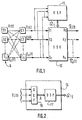
- FIG. 1 are shown the primary sources 5, S1 to Sn, constituted for example by different radio frequency transmitters. To identify and separate these transmitters, place sensors C1 - Cn at various reception points. Each of these sensors is for example an antenna followed by an amplifier and a demodulator. The sensors supply signals E 1 (t) to E n (t) originating from mixtures of primary signals X 1 (t) to X n (t) which either are delivered directly by the sources S1 to Sn, or are used to modulate signals broadcast by sources S1 to Sn.
- E 1 (t) to E n (t) originating from mixtures of primary signals X 1 (t) to X n (t) which either are delivered directly by the sources S1 to Sn, or are used to modulate signals broadcast by sources S1 to Sn.
- the mixtures that occur between signals primaries are directly related to the propagation of these signals in space. These mixtures can be made completely or approximately linear and instantaneous using suitable transmitters and sensors, in particular by choosing the types of modulators and demodulators used, as well as operating frequencies of the system, for example by choosing transmitters using amplitude modulation.
- the detected signals E 1 (t) to E n (t) enter a source separation unit 10 which delivers estimated primary signals X and 1 (t) to X and n (t), the variable t being for example time.
- the mixed input signals E 1 (t) to E n (t) are instantaneous linear mixtures resulting, in the general case, from p unknown primary signals X 1 (t) to X p (t) such that: with 1 ⁇ i ⁇ n and 1 ⁇ j ⁇ p, i and j being current variables.
- the coefficients a ij are mixing coefficients which define the contributions of the signal X j (t) to the mixed signal E i (t).
- the mixing coefficients a ij which are unknown, are constant or slowly variable.
- equation (1) becomes: for 1 ⁇ i ⁇ n, 1 ⁇ j ⁇ p and j ⁇ i.
- the normalized mixing coefficients ⁇ ij will hereinafter simply be called mixing coefficients.
- the separation unit 10 uses separation coefficients C ki . It delivers the estimated primary signals by performing the inverse transformation (k current output index): with 1 ⁇ i ⁇ n and 1 ⁇ k ⁇ n
- the separation coefficients C ki are determined in the separation unit 10 from estimated mixing coefficients ⁇ and ij which constitute an estimate of the mixing coefficients ⁇ ij which are unknown. This estimation is carried out in a characterization unit 15 which, from the input signals E i (t), delivers the estimated mixing coefficients (FIG. 1).
- the separation unit (10) can have a recursive structure using separation coefficients d ki .
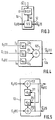
- FIG. 2 represents a diagram of the characterization unit 15. It includes an estimation unit 16 followed by a unit 17 for calculating estimated coefficients.
- the estimation unit 16 receives all of the input signals E i (t) and delivers an estimate of a set A of quantities characteristic of the input signals E i (t). These quantities characteristic of the set A are chosen so that it is possible firstly to calculate them from the input signals E i (t), and secondly to express them by using the mixing coefficients ⁇ ij and a set B of characteristic quantities relating to the normalized primary signals Y j (t) although these are unknown, the characteristic quantities of the set B being of the same nature as the characteristic quantities of the set A.
- the estimation unit 16 determines an estimate of the set A, an estimate sufficient for it to be possible to deduce therefrom estimated coefficients ⁇ and ij of mixing in the unit 17 for calculating coefficients estimated.
- the characteristic quantities constituting the set A are self-cumulants associated with each mixed signal E i (t) previously centered, as well as crossed cumulants associated with each pair of mixed signals E f (t) and E g (t) previously centered (f and g being current integer indices, 1 ⁇ f ⁇ n, 1 ⁇ g ⁇ n).
- the characteristic quantities constituting the set B are self-cumulants associated with each normalized primary signal Y i (t) previously centered. The definition of these quantities is in itself well known to those skilled in the art.
- the cumulants (auto and of order greater than 2.
- the easiest cumulants to calculate are the ones with the lowest order. Nevertheless the cumulants of order three must be large enough for the calculation is limited to these cumulants only. This condition is not meets only for a limited number of types of sources.
- the cumulants are calculated of order 4 which allows to cover a wider range of signals encountered experimentally. Those skilled in the art can choose cumulants having a different order without departing from the framework of the invention.
- cumulants For the sake of clarity, a reminder of the definitions of cumulants is provided below, being limited only to cumulants necessary for the example treated, that is to say to the self-cumulants and to order 4 cross cumulants, limiting themselves to two signals, and without involving a time difference between the two signals considered.
- the cumulants cum4 (equations 13 and 17) and the cumulants cum31 (equations 14 and 16) for example are generalized respectively such that: with 1 ⁇ j ⁇ n, j ⁇ r and j ⁇ s, and 1 ⁇ r ⁇ n, 1 ⁇ s ⁇ n, and r ⁇ s, r, s being current integer variables.
- this calculation (case with two sources and two sensors) is to determine the mixing coefficients ⁇ 12 , ⁇ 21 . In reality, the calculation is carried out to determine only estimates of the mixing coefficients ⁇ 12 , ⁇ 21 in the form of estimated coefficients ⁇ and 12 , ⁇ and 21 .
- the calculation of the estimated coefficients ⁇ and 12 , ⁇ and 21 is carried out in the characterization unit (15) represented in FIG. 2.
- the estimation unit (16) determines the estimates of the cumulants of the mixed signals, then the unit (17) for calculating estimated coefficients delivers the estimated coefficients ⁇ and 12 , ⁇ and 21 .
- the estimation unit (16) calculates the cumulants cum4 (e1) to cum4 (e2) according to equations 8 to 12.
- the estimation unit DSP can consist of a computer, a microprocessor or a digital signal processing unit.
- the coefficient calculation unit 17 which calculates the mixing coefficients ⁇ 12 and ⁇ 21 from equations 13 to 17.
- the resolution of these equations provides no not the true coefficients ⁇ 12 and ⁇ 21 but near values constituting the estimated coefficients ⁇ and 12 and a 21 because they are estimated cumulants and not exact cumulants which are used to solve equations 13 to 17.
- the coefficient calculation unit 17 can also be made up of a computer, a microprocessor or a digital signal processing device applying a method solving equations.
- the unit for calculating the coefficients 17 is then programmed to solve equations 20 and 21 for example using one of the known methods indicated previously.
- equation 22 is only to link the unknown coefficients ⁇ ij with the set A without taking into consideration the set B which, although also unknown, is not to be determined.
- This function F (.) Is characteristic of the number of primary and sensor signals necessary for the implementation of the application in question. This is an advantage because the system is by itself independent of the other parameters of the application. It is easy to see that the unit for calculating coefficients 17 can undergo prior training in a first phase for solve the function F (.). In a second phase, the data measured experimentally can be processed according to the method learned. However, it is known that it is possible to obtain a approximation of a function F (.) by a function G (.) using a multilayer neural network or a multilayer perceptron or a neural network in a tree.
- the use of a neural network is particularly interesting because it does not require solving, each time, for each batch of cumulants, the equations 13 to 17 in the separation system itself. It suffices that the neural network learns beforehand to solve the G (.) Function and then use it for each batch of cumulants, the source separation system thus becoming dedicated to the type of G (.) Function learned. To adapt the source separation system to a different number of sensors or to a different number of primary signals to be separated, it suffices to make the neural network relearn the new function G (.) Relative to this new number of sensors and / or to this new number of primary signals.
- Learning the neural network will therefore consist in determining the synaptic coefficients of the neural network in order to approximate the correspondence input signals / output signals of the neural network in accordance with the results of equations 13 to 17 precalculated. This has the advantage of not having to solve complex equations 13 to 17.
- the estimated mixing coefficients ⁇ and ij thus calculated are entered into the source separation unit 10 to disentangle the input signals E i (t) and provide estimated primary signals X and k (t).
- the source separation carried out by the source separation unit 10 can be written in the form: for a direct structure, and for a recursive structure.
- the coefficients C ki , d ki are separation coefficients which are deduced from the estimated mixing coefficients ⁇ and ij which enter the separation unit 10.
- the first of these transformations corresponds to the case where the estimated primary signal corresponding to the primary signal of kth rank is found on the k th output of the separation unit.
- the source separation unit 10 comprises the transformation unit 11 which transforms the estimated coefficients ⁇ and ij of mixtures into separation coefficients C ki , d ki and a separation subunit 12 proper which receives, on a plurality of inputs, the mixed signals E i (t) and which delivers at least one estimated primary signal X and k (t).
- FIG. 4 represents a part of a 12 k separation subunit with direct structure. It comprises a plurality of inputs I 1 to I n each receiving a mixed signal E 1 (t) to E n (t). Each of these inputs is connected to a multiplication means 13 1 to 13 n of said signal by the separation coefficient C k1 to C kn assigned to the input. The outputs of all, the multiplication means 13 1 to 13 n are connected to a summator 125 to add all the signals and deliver the estimated primary signal X and k (t).
- the separation sub-unit 12 (FIG. 3) contains as many partial sub-units 12 k as there are estimated primary signals X and k (t).
- FIG. 5 represents a separation subunit 12 having a recursive structure for an example intended to deliver two primary signals estimated X and 1 (t) and X and 2 (t) from two mixed signals E 1 (t) and E 2 (t).
- This structure includes a first adder 112 having an input connected to the signal E 1 (t) and an output which delivers the estimated primary signal X and 1 (t).
- a second adder 212 has an input connected to the signal E 2 (t) and an output which delivers the estimated primary signal X and 2 (t).
- Another input of the first summer 112 is connected to the output of the second summer 212 through a multiplication means 111 which weights the output signal of the second summer by a coefficient -d 12 .
- Another input of the second adder 212 is connected to the output of the first adder 112 through another multiplication means 211 which weights the output signal of the first adder by a coefficient -d 21 .
- the summers 112, 212 and the multiplication means 111, 211 can be part of a computer, a microprocessor or a digital signal processing unit correctly programmed to perform the functions described.
Landscapes
- Engineering & Computer Science (AREA)
- Physics & Mathematics (AREA)
- General Physics & Mathematics (AREA)
- Radar, Positioning & Navigation (AREA)
- Remote Sensing (AREA)
- Computer Vision & Pattern Recognition (AREA)
- Data Mining & Analysis (AREA)
- Theoretical Computer Science (AREA)
- Evolutionary Computation (AREA)
- Bioinformatics & Cheminformatics (AREA)
- Bioinformatics & Computational Biology (AREA)
- Evolutionary Biology (AREA)
- Artificial Intelligence (AREA)
- General Engineering & Computer Science (AREA)
- Life Sciences & Earth Sciences (AREA)
- Computer Networks & Wireless Communication (AREA)
- Signal Processing (AREA)
- Complex Calculations (AREA)
- Circuits Of Receivers In General (AREA)
- Details Of Aerials (AREA)
- Cable Transmission Systems, Equalization Of Radio And Reduction Of Echo (AREA)
- Noise Elimination (AREA)
- Mobile Radio Communication Systems (AREA)
- Compression, Expansion, Code Conversion, And Decoders (AREA)
Claims (6)
- System zur Trennung von Quellen für die Verarbeitung von Empfangssignalen (E1(t)..En(t)) in momentanen linearen Mischungen von Primärsignalen (X1(t)..Xn(t)) aus diesen Quellen (S1..S2) und zum Liefern mindestens eines abgeschätzten Primärsignals (X and1(t)) unter Verwendung von Mischungskoeffizienten bei den Mischungen, ein System mit Vorrichtung (10) zur Trennung der Quellen mit einer Vielzahl, mit den Empfangssignalen (E1(t)..En(t)) verbundenen Eingängen (I1..In) und mindestens einem Ausgang (R1) zum Liefern des abgeschätzten Primärsignals (X and1(t)), wobei die Vorrichtung (10) zur Trennung der Quellen unter adaptiver Bestimmung der Trennungskoeffizienten (Ckl..Ckn) für die Entnahme der abgeschätzten Primärsignale dient, dadurch gekennzeichnet, daß das System eine Vorrichtung (15) zur Charakterisierung enthält, mit einer Vielzahl, mit den Empfangssignalen (E1(t)..En(t)) verbundenen Eingängen, um davon die Mischungskoeffizienten abzuschätzen, und mindestens einem Ausgang, um die abgeschätzten Mischungskoeffizienten (α andij) zu liefern der, wobei die Vorrichtung (10) zur Trennung mindestens einen weiteren Eingang hat, um die abgeschätzten Mischungskoeffizienten (α andij) zu empfangen, und die Vorrichtung (10) zur Trennung eine Vorrichtung (11) zur Transformation der abgeschätzten Mischungskoeffizienten (α andij) in Trennungskoeffizienten (CKi) aufweist.
- System nach Anspruch 1, dadurch gekennzeichnet, daß die Vorrichtung (15) zur Charakterisierung eine Vorrichtung (16) zur Abschätzung aufweist, um an den Empfangssignalen Kumulationsabschätzungen einer Größenordnung über zwei zu berechnen, und eine Vorrichtung (17) zur Berechnung der abgeschätzten Koeffizienten, um die Abschätzungen der besagten Kumulationen in abgeschätzte Mischungskoeffizienten (α andij): zu transformieren.
- System nach Anspruch 2, dadurch gekennzeichnet, daß die Vorrichtung (17) zur Berechnung der abgeschätzten Koeffizienten über ein neuronales Netzwerk verfügt, um die Abschätzungen der besagten Kumulationen nach einer vorbestimmten Transformationsfunktion in abgeschätzte Mischungskoeffizienten (α andij): zu transformieren.
- System nach Anspruch 2 oder 3, dadurch gekennzeichnet, daß die Vorrichtung (10) zur Trennung eine Vorrichtung (12K) direkter Struktur ist, während die Vorrichtung (10) zur Trennung eine Einheit (11) zur Transformation der abgeschätzten Mischungskoeffizienten (α andij) in Trennungskoeffizienten (CKi), der direkten Struktur angepaßt, aufweist.
- System nach Anspruch 2 oder 3, dadurch gekennzeichnet, daß die Vorrichtung (10) zur Trennung eine Vorrichtung (12) rekursiver Struktur ist, während die Vorrichtung (10) zur Trennung eine Einheit zur Transformation der abgeschätzten Mischungskoeffizienten (α andij) in Trennungskoeffizienten (-d12, -d21), der rekursiven Struktur angepaßt, aufweist.
- Methode zur Trennung von Quellen für die Verarbeitung von Empfangssignalen (E1(t)..En(t)) in momentanen linearen Mischungen von Primärsignalen (X1(t)..Xn(t)) aus diesen Quellen (S1..S2) und zum Liefern mindestens eines abgeschätzten Primärsignals (X and1(t)) unter Verwendung von Mischungskoeffizienten bei den Mischungen, eine Methode mit Vorrichtung (10) zur Trennung der Quellen mit einer Vielzahl, mit den Empfangssignalen (E1(t)..En(t)) verbundenen Eingängen (I1..In) und mindestens einem Ausgang (R1) zum Liefern des abgeschätzten Primärsignals (X and1(t)), wobei die Methode einen Schritt zur Berechnung der Trennungskoeffizienten (Ckl..Ckn) enthält, der für die Entnahme der abgeschätzten Primärsignale dient, dadurch gekennzeichnet, daß sie besteht aus:einem Abschätzungsschritt (15), um die Mischungskoeffizienten anhand der Empfangssignale (E1(+)..En(+)) abzuschätzen, um die abgeschätzten Mischungskoeffizienten (α andij) zu erhalten; undeinem Transformationsschritt (11), um die abgeschätzten Mischungskoeffizienten (α andij) in Trennungskoeffizienten (Cki) zu transformieren.
Applications Claiming Priority (2)
| Application Number | Priority Date | Filing Date | Title |
|---|---|---|---|
| FR9502051 | 1995-02-22 | ||
| FR9502051A FR2730881A1 (fr) | 1995-02-22 | 1995-02-22 | Systeme pour estimer des signaux recus sous forme de signaux melanges |
Publications (2)
| Publication Number | Publication Date |
|---|---|
| EP0729037A1 EP0729037A1 (de) | 1996-08-28 |
| EP0729037B1 true EP0729037B1 (de) | 2001-07-04 |
Family
ID=9476403
Family Applications (1)
| Application Number | Title | Priority Date | Filing Date |
|---|---|---|---|
| EP96200366A Expired - Lifetime EP0729037B1 (de) | 1995-02-22 | 1996-02-14 | System zur Abschätzung von Empfangssignalen in einer Mischung von Signalen |
Country Status (8)
| Country | Link |
|---|---|
| US (1) | US5909646A (de) |
| EP (1) | EP0729037B1 (de) |
| JP (1) | JP3838382B2 (de) |
| KR (1) | KR100415335B1 (de) |
| DE (1) | DE69613608T2 (de) |
| FR (1) | FR2730881A1 (de) |
| HK (1) | HK1012715A1 (de) |
| TW (1) | TW428401B (de) |
Families Citing this family (18)
| Publication number | Priority date | Publication date | Assignee | Title |
|---|---|---|---|---|
| SE511496C2 (sv) | 1995-05-03 | 1999-10-11 | Ulf Lindgren | Förfarande vid signalseparation |
| US6185309B1 (en) * | 1997-07-11 | 2001-02-06 | The Regents Of The University Of California | Method and apparatus for blind separation of mixed and convolved sources |
| US6167417A (en) * | 1998-04-08 | 2000-12-26 | Sarnoff Corporation | Convolutive blind source separation using a multiple decorrelation method |
| SE521024C2 (sv) * | 1999-03-08 | 2003-09-23 | Ericsson Telefon Ab L M | Metod och anordning för att separera en blandning av källsignaler |
| JP2001053654A (ja) * | 1999-08-16 | 2001-02-23 | Matsushita Electric Ind Co Ltd | 信号分離装置、信号分離方法及び記録媒体 |
| US7310624B1 (en) * | 2000-05-02 | 2007-12-18 | International Business Machines Corporation | Methods and apparatus for generating decision trees with discriminants and employing same in data classification |
| US6701170B2 (en) * | 2001-11-02 | 2004-03-02 | Nellcor Puritan Bennett Incorporated | Blind source separation of pulse oximetry signals |
| US6990519B2 (en) * | 2001-11-08 | 2006-01-24 | Texas Instruments Incorporated | Use of a directed acyclic organization structure for selection and execution of consistent subsets of rewrite rules |
| US6993440B2 (en) * | 2002-04-22 | 2006-01-31 | Harris Corporation | System and method for waveform classification and characterization using multidimensional higher-order statistics |
| US6711528B2 (en) * | 2002-04-22 | 2004-03-23 | Harris Corporation | Blind source separation utilizing a spatial fourth order cumulant matrix pencil |
| US7366564B2 (en) | 2002-08-23 | 2008-04-29 | The United States Of America As Represented By The Secretary Of The Navy | Nonlinear blind demixing of single pixel underlying radiation sources and digital spectrum local thermometer |
| US7187326B2 (en) * | 2003-03-28 | 2007-03-06 | Harris Corporation | System and method for cumulant-based geolocation of cooperative and non-cooperative RF transmitters |
| US6993460B2 (en) | 2003-03-28 | 2006-01-31 | Harris Corporation | Method and system for tracking eigenvalues of matrix pencils for signal enumeration |
| US6954530B2 (en) * | 2003-07-09 | 2005-10-11 | Utah State University | Echo cancellation filter |
| US20100265139A1 (en) * | 2003-11-18 | 2010-10-21 | Harris Corporation | System and method for cumulant-based geolocation of cooperative and non-cooperative RF transmitters |
| KR100600313B1 (ko) * | 2004-02-26 | 2006-07-14 | 남승현 | 다중경로 다채널 혼합신호의 주파수 영역 블라인드 분리를 위한 방법 및 그 장치 |
| FR2868541B1 (fr) * | 2004-03-30 | 2006-05-26 | Thales Sa | Procede de localisation aveugle large bande d'un ou plusieurs emetteurs a partir d'un porteur defilant |
| WO2008002205A1 (en) * | 2006-06-27 | 2008-01-03 | Telefonaktiebolaget Lm Ericsson (Publ) | A radio frequency emitter detection and location method and system |
Family Cites Families (12)
| Publication number | Priority date | Publication date | Assignee | Title |
|---|---|---|---|---|
| US4513383A (en) * | 1981-09-24 | 1985-04-23 | Rockwell International Corporation | Separation of communication signals in an adaptive antenna array |
| US4780721A (en) * | 1984-07-23 | 1988-10-25 | The Commonwealth Of Australia | Adaptive antenna array |
| US4965732A (en) * | 1985-11-06 | 1990-10-23 | The Board Of Trustees Of The Leland Stanford Junior University | Methods and arrangements for signal reception and parameter estimation |
| US5150323A (en) * | 1989-08-11 | 1992-09-22 | Hughes Aircraft Company | Adaptive network for in-band signal separation |
| FR2657173B1 (fr) * | 1990-01-16 | 1992-04-10 | Thomson Csf | Procede et dispositif de separation de signaux en temps reel. |
| US5272656A (en) * | 1990-09-21 | 1993-12-21 | Cambridge Signal Technologies, Inc. | System and method of producing adaptive FIR digital filter with non-linear frequency resolution |
| IL101556A (en) * | 1992-04-10 | 1996-08-04 | Univ Ramot | Multi-channel signal separation using cross-polyspectra |
| US5459668A (en) * | 1993-06-04 | 1995-10-17 | University Of Southern California | Method and apparatus for signal analysis employing a virtual cross-correlation computer |
| US5383164A (en) * | 1993-06-10 | 1995-01-17 | The Salk Institute For Biological Studies | Adaptive system for broadband multisignal discrimination in a channel with reverberation |
| JP3424761B2 (ja) * | 1993-07-09 | 2003-07-07 | ソニー株式会社 | 音源信号推定装置および方法 |
| CN1167215C (zh) * | 1994-06-23 | 2004-09-15 | Ntt移动通信网株式会社 | 码分多址联接解调方法 |
| US5706402A (en) * | 1994-11-29 | 1998-01-06 | The Salk Institute For Biological Studies | Blind signal processing system employing information maximization to recover unknown signals through unsupervised minimization of output redundancy |
-
1995
- 1995-02-22 FR FR9502051A patent/FR2730881A1/fr not_active Withdrawn
-
1996
- 1996-02-14 EP EP96200366A patent/EP0729037B1/de not_active Expired - Lifetime
- 1996-02-14 DE DE69613608T patent/DE69613608T2/de not_active Expired - Lifetime
- 1996-02-19 JP JP03099896A patent/JP3838382B2/ja not_active Expired - Fee Related
- 1996-02-20 US US08/602,535 patent/US5909646A/en not_active Expired - Lifetime
- 1996-02-21 KR KR1019960004019A patent/KR100415335B1/ko not_active IP Right Cessation
- 1996-02-29 TW TW085102380A patent/TW428401B/zh not_active IP Right Cessation
-
1998
- 1998-12-18 HK HK98114037A patent/HK1012715A1/xx not_active IP Right Cessation
Also Published As
| Publication number | Publication date |
|---|---|
| DE69613608D1 (de) | 2001-08-09 |
| FR2730881A1 (fr) | 1996-08-23 |
| TW428401B (en) | 2001-04-01 |
| US5909646A (en) | 1999-06-01 |
| JP3838382B2 (ja) | 2006-10-25 |
| KR100415335B1 (ko) | 2004-05-20 |
| KR960032928A (ko) | 1996-09-17 |
| HK1012715A1 (en) | 1999-08-06 |
| EP0729037A1 (de) | 1996-08-28 |
| JPH08316855A (ja) | 1996-11-29 |
| DE69613608T2 (de) | 2002-05-08 |
Similar Documents
| Publication | Publication Date | Title |
|---|---|---|
| EP0729037B1 (de) | System zur Abschätzung von Empfangssignalen in einer Mischung von Signalen | |
| EP0487376B1 (de) | Verfahren und Einrichtung zur Modulationserkennung | |
| EP0749083B1 (de) | Verfahren und Einrichtung zur Frequenzspektrumbestimmung eines Signals | |
| EP0219392A1 (de) | Rechnereinrichtung von einer sich verschiebenden, nichtrekursiven, diskreten Fourier-Transformation und ihr Gebrauch in einem Radarsystem | |
| EP2321769A1 (de) | Verfahren zur erkennung von formen und system zur anwendung dieses verfahrens | |
| EP0223657B1 (de) | Rechnungseinrichtung von diskreter Fouriertransformation und seine Anwendung auf einem Radarsystem | |
| FR2759824A1 (fr) | Systeme de separation de sources non stationnaires | |
| WO2015158615A1 (fr) | Procédé de détection numérique | |
| EP0661077B1 (de) | Medizinische Vorrichtung, welche ein Nutzsignal aus Störsignalen herausfiltert | |
| EP3506174A1 (de) | System zur demodulation oder blindsuche der eigenschaften von digitalen telekommunikationssignalen | |
| EP0673113B1 (de) | Signalquellencharakterisiersystem | |
| EP0481895A2 (de) | Verfahren und Einrichtung zur Übertragung mit niedriger Bitrate einer Sprachsignals mittels CELP-Codierung | |
| EP0692883B1 (de) | Verfahren zur blinden Entzerrung, und dessen Anwendung zur Spracherkennung | |
| EP0933885A1 (de) | Verfahren zur zyklischen Detektion von digitalen cyclostationären Funksignalen mit Polarisationsdiversität | |
| EP0401927A1 (de) | Lernverfahren, neuronales Netz und Rechner zur Simulation eines solchen neuronalen Netzes | |
| EP0533540A1 (de) | Internes Verbindungsverfahren für neuronale Netzwerke | |
| FR2858512A1 (fr) | Procede et dispositif de traitement de donnees sonores en contexte ambiophonique | |
| EP0786920A1 (de) | Übertragungssystem für in Wechselbeziehung stehende Signale | |
| EP1246373A1 (de) | Verfahren und Vorrichtung zur Interferenzsbehandlung in empfangenen Signalen van einem Netzwerk | |
| EP1605440B1 (de) | Verfahren zur Quellentrennung eines Signalgemisches | |
| EP1478096B1 (de) | Selbstanpassende Vorrichtung und Verfahren zur Interferenz-Unterdruckung | |
| FR2679083A1 (fr) | Procede et dispositif automatique de separation de sources. | |
| WO2015185074A1 (fr) | Filtrage selectif amont en modulation de frequence a base de reseau de neurones | |
| EP3506173A1 (de) | System zur demodulation oder blindsuche von digitalen telekommunikationssignalen | |
| FR3131995A1 (fr) | Support de calculs sur nombres reels au niveau des commutateurs physiques |
Legal Events
| Date | Code | Title | Description |
|---|---|---|---|
| PUAI | Public reference made under article 153(3) epc to a published international application that has entered the european phase |
Free format text: ORIGINAL CODE: 0009012 |
|
| AK | Designated contracting states |
Kind code of ref document: A1 Designated state(s): DE ES FR GB IT |
|
| 17P | Request for examination filed |
Effective date: 19970228 |
|
| 17Q | First examination report despatched |
Effective date: 19991019 |
|
| RAP1 | Party data changed (applicant data changed or rights of an application transferred) |
Owner name: KONINKLIJKE PHILIPS ELECTRONICS N.V. |
|
| GRAG | Despatch of communication of intention to grant |
Free format text: ORIGINAL CODE: EPIDOS AGRA |
|
| GRAG | Despatch of communication of intention to grant |
Free format text: ORIGINAL CODE: EPIDOS AGRA |
|
| GRAH | Despatch of communication of intention to grant a patent |
Free format text: ORIGINAL CODE: EPIDOS IGRA |
|
| GRAH | Despatch of communication of intention to grant a patent |
Free format text: ORIGINAL CODE: EPIDOS IGRA |
|
| GRAA | (expected) grant |
Free format text: ORIGINAL CODE: 0009210 |
|
| AK | Designated contracting states |
Kind code of ref document: B1 Designated state(s): DE ES FR GB IT |
|
| REF | Corresponds to: |
Ref document number: 69613608 Country of ref document: DE Date of ref document: 20010809 |
|
| ITF | It: translation for a ep patent filed |
Owner name: ING. C. GREGORJ S.P.A. |
|
| GBT | Gb: translation of ep patent filed (gb section 77(6)(a)/1977) |
Effective date: 20010828 |
|
| REG | Reference to a national code |
Ref country code: GB Ref legal event code: IF02 |
|
| PG25 | Lapsed in a contracting state [announced via postgrant information from national office to epo] |
Ref country code: ES Free format text: LAPSE BECAUSE OF FAILURE TO SUBMIT A TRANSLATION OF THE DESCRIPTION OR TO PAY THE FEE WITHIN THE PRESCRIBED TIME-LIMIT Effective date: 20020131 |
|
| PLBE | No opposition filed within time limit |
Free format text: ORIGINAL CODE: 0009261 |
|
| STAA | Information on the status of an ep patent application or granted ep patent |
Free format text: STATUS: NO OPPOSITION FILED WITHIN TIME LIMIT |
|
| 26N | No opposition filed | ||
| REG | Reference to a national code |
Ref country code: GB Ref legal event code: 746 Effective date: 20021014 |
|
| REG | Reference to a national code |
Ref country code: FR Ref legal event code: D6 |
|
| PGFP | Annual fee paid to national office [announced via postgrant information from national office to epo] |
Ref country code: IT Payment date: 20060228 Year of fee payment: 11 |
|
| REG | Reference to a national code |
Ref country code: GB Ref legal event code: 732E |
|
| REG | Reference to a national code |
Ref country code: FR Ref legal event code: TP |
|
| PG25 | Lapsed in a contracting state [announced via postgrant information from national office to epo] |
Ref country code: IT Free format text: LAPSE BECAUSE OF NON-PAYMENT OF DUE FEES Effective date: 20070214 |
|
| PGFP | Annual fee paid to national office [announced via postgrant information from national office to epo] |
Ref country code: FR Payment date: 20100223 Year of fee payment: 15 |
|
| PGFP | Annual fee paid to national office [announced via postgrant information from national office to epo] |
Ref country code: GB Payment date: 20100202 Year of fee payment: 15 Ref country code: DE Payment date: 20100226 Year of fee payment: 15 |
|
| GBPC | Gb: european patent ceased through non-payment of renewal fee |
Effective date: 20110214 |
|
| REG | Reference to a national code |
Ref country code: FR Ref legal event code: ST Effective date: 20111102 |
|
| REG | Reference to a national code |
Ref country code: DE Ref legal event code: R119 Ref document number: 69613608 Country of ref document: DE Effective date: 20110901 |
|
| PG25 | Lapsed in a contracting state [announced via postgrant information from national office to epo] |
Ref country code: FR Free format text: LAPSE BECAUSE OF NON-PAYMENT OF DUE FEES Effective date: 20110228 |
|
| PG25 | Lapsed in a contracting state [announced via postgrant information from national office to epo] |
Ref country code: GB Free format text: LAPSE BECAUSE OF NON-PAYMENT OF DUE FEES Effective date: 20110214 |
|
| PG25 | Lapsed in a contracting state [announced via postgrant information from national office to epo] |
Ref country code: DE Free format text: LAPSE BECAUSE OF NON-PAYMENT OF DUE FEES Effective date: 20110901 |