EP0728899B1 - Security closure - Google Patents
Security closure Download PDFInfo
- Publication number
- EP0728899B1 EP0728899B1 EP96301154A EP96301154A EP0728899B1 EP 0728899 B1 EP0728899 B1 EP 0728899B1 EP 96301154 A EP96301154 A EP 96301154A EP 96301154 A EP96301154 A EP 96301154A EP 0728899 B1 EP0728899 B1 EP 0728899B1
- Authority
- EP
- European Patent Office
- Prior art keywords
- panel
- support member
- opening
- security closure
- building
- Prior art date
- Legal status (The legal status is an assumption and is not a legal conclusion. Google has not performed a legal analysis and makes no representation as to the accuracy of the status listed.)
- Expired - Lifetime
Links
Images


Classifications
-
- E—FIXED CONSTRUCTIONS
- E06—DOORS, WINDOWS, SHUTTERS, OR ROLLER BLINDS IN GENERAL; LADDERS
- E06B—FIXED OR MOVABLE CLOSURES FOR OPENINGS IN BUILDINGS, VEHICLES, FENCES OR LIKE ENCLOSURES IN GENERAL, e.g. DOORS, WINDOWS, BLINDS, GATES
- E06B9/00—Screening or protective devices for wall or similar openings, with or without operating or securing mechanisms; Closures of similar construction
- E06B9/02—Shutters, movable grilles, or other safety closing devices, e.g. against burglary
- E06B9/04—Shutters, movable grilles, or other safety closing devices, e.g. against burglary of wing type, e.g. revolving or sliding
Definitions
- This invention relates to a security closure for use in covering openings in a building, for example windows or the like.
- a building If a building is left vacant for more than a short period of time, for example to carry out renovation works, it becomes vulnerable to people breaking into the building for the purposes of theft squatting or vandalism.
- the normal windows of a building do not provide a high degree of security so it is known to cover the windows to make it more difficult to enter into the building.
- a rudimentary way of covering a window is to fasten a wooden board over the outside of the window but this is relatively easy to remove by someone determined to enter the building.
- a security closure is formed as a metal panel having a circumferential side wall with an inwardly turned rim.
- the panel is held with the rim against the outside of the opening by means of support beams captively retained by the inwardly turned rim of the panel and which are tied by connecting rods to anchor beams spanning the opening on the inside of the building.
- the connecting rod is tightened so the wall of the building around the opening is clamped between the panel and the anchor beam.
- the panel In order to allow the connecting tie to pass through a convenient position in the opening, for example through an open light in the window, the panel is arranged so that the support beam can slide parallel to the face of the panel whilst being retained by the rim and the support beam is designed so that the connecting tie is slidable along the support and anchor beams thereby allowing the connecting tie to be located at most positions within the plane of the panel.
- nut and bolt connections are difficult to secure quickly. In some instances the panel slips from position before the connection can be secured. This presents particular difficulties when securing closures on windows on the upper levels of buildings where the panel could fall from the building or unbalance a worker which is particularly hazardous with heavy security closures.
- the present invention includes embodiments which seek to address the above disadvantages.
- One of the benefits of the systems presently used is that personnel within the building should not be able to remove a panel once installed. This reduces the instances that the building is left unsecured by the panel removal by unauthorised personnel.
- the present invention seeks to provide a panel with an emergency release mechanism which allows at least some of the panels on a building to be released in the event of emergencies.
- the emergency release will indicate whether or not it has been used thus preventing unauthorised tampering with the emergency release system.
- the panel can be hinged away from the opening by means of the pivot provided on the end of the support member fixed to the edge of the panel.
- the security closure will be provided with a plurality of the support members.
- the hinged fixing means is fixed to the circumferential sidewall and, advantageously, the hinged fixing means provides movement of the panel away from the building prior to the said pivoting to allow a smooth movement of the panel even though the pivot axis is out of the plane of the wall.
- This prior movement may be provided by a second pivot provided in the hinged fixing means with an axis substantially parallel to the first-mentioned pivot and spaced along the support member further from the said one edge than the first-mentioned pivot.
- the releasable securing means of the or each support member comprises a connecting anchor connecting the support member to a panel fixing mounted on the panel.
- the panel fixing may comprise a lever bracket which comprises a housing mounted on the interior of the panel with an opening on the interior side of the housing through which opening the connecting anchor is arranged to fit, the connecting anchor being fitted through said opening and engaged by a lever in the housing when the support member is secured by the releasable securing means, and the connecting anchor being dis-engaged from the lever and being removable from the housing when the support member is released from releasable securing means.
- the or each releasable securing means is releasable by means of release handle operatively connected to the or each securing means, the release handle being mounted on the interior of the panel.
- the handle is advantageously positioned to be easily accessible from inside the building. This is accomplished by the handle position being independent of the releasable securing means position. This is particularly useful when the panel is installed over a window which has lights through which the handle can be made accessible.
- the independent positioning of the handle means that the fixing points of the support members fixings can be optimised in the panel as the fixings do not need to be accessible to any user.
- an indicator is provided which indicates whether or not the releasable securing means have been released.
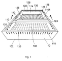
- a security closure comprises a panel 102 and an elongate, telescopic support member 104.
- the panel 102 is formed from a cut and folded sheet of galvanised steel. This embodiment has a rectangular face 106 through which are punched an array of regularly spaced through-holes 108 which make ventilation and light available to the interior of a building to which the panel 102 is applied without allowing access to the support beam 104 so as preserve the security of the closure.
- the panel has four side wall portions 111, 112, 114, 116, which bound the periphery of the rectangular front face 106.
- the side walls 110, 112, 114, 116 are trapezoidal and opposed pairs of side walls diverge away from the face plate 106.
- the top of each side wall portion 110, 112, 114, 116 is provided with an inwardly-turned, L-shaped rim 118, 120, 122, 124 as is more clearly shown in Figures 2 to 4.
- Each rim 118, 120, 122, 124 has an upper planar portion 126 (in the orientation of the closure as depicted in the Figures) parallel to the front face 106 which in use of the panel is placed in abutment with the portion of the building surrounding the opening to be closed.
- the innermost portion of each of the rims 118 is in the form of a lip downwardly extending lip 128 extending towards the front face 106 parallel with the respective side wall 110, 112, 114, 116.
- Each of the side wall portions 110, 112, 114, 116 of the panel 102 is provided with a row of regularly spaced apertures 130 which constitute part of the interlocking means preventing lateral movements of the support member 104 as will be described in more detail later.
- the apertures 130 are generally rectangular with curved top and bottom edges and have their principal axes perpendicular to the plane of the front face 106.
- the support member 104 is telescopic and comprises a first elongate beam 132 of C-shaped cross section within which is received a second elongate beam 134 of U-shaped cross section.
- the first beam 132 is in the form of a generally rectangular tube with an open channel or slot 136 in the uppermost face of the beam 132.
- a connector (not shown) can be inserted through the slot 136 and fixed to the support member 104 by means of a captive locking mechanism (not shown), for example, retained within the support member 104 in known fashion.
- the second beam 134 has a planar base 138 and a pair of opposed, parallel side walls 140 extending upwards at right angles to the base 138.
- the end of the second beam 134 which projects from within the first beam 132 is capped with a rectangular plate 142 which extends above the side walls 140.
- the end of the first elongate beam 132 furthest away from the plate 142 is capped with a similar rectangular plate 144 which similarly extends above the second elongate beam 132.
- first and second elongate beams 132 and 134 to which the plates 144 and 142, respectively are fixed are angled such that the plates 142 and 144 diverge at the same angle as each pair of opposed side walls and so are parallel to those side walls when the side beam 104 is parallel to the face plate 106 and the other two side walls 110 and 114 in the arrangement shown in the Figures.
- Cylindrical pins 146 and 148 are welded perpendicularly to the centres of each of the plates 142 and 144 respectively.
- the pins 144 and 146 are dimensioned to be receivable by the apertures 130 in side wall portions 110, 112, 114, and 116.
- the base 138 of the second beam 134 is provided with a central slot 150 which extends the length of the second elongate beam 134.
- a metal plate 152 is welded in position across the second elongate beam 134 between the side walls 140 with a through-hole in the plate 152 forming a first anchor point for a first end of a spring 154.
- the base 138 of the first beam 132 has an upstanding tab 156 formed by punching through a portion of the base 138 and dimensioned so it can move within the channel 150 in the second beam 134.
- a through-hole is provided in the tab 156 to provide a second anchor point to the second end of the spring 154.
- the spring 154 urges the plate 152 and the tab 156 together thereby urging the first portion 134 to telescope out of the first portion 132 to the position as shown in Figure 2.
- the support beam 104 can be shortened by pressing the second beam 134 into the first beam 132 by hand to the position as shown in Figure 3. When in this shortened configuration the support beam 104 can be placed within the side walls 110, 112, 114, 116 of the panel 102 beneath the rims 118, 120, 122, 124.
- the support member 4 is shown partially inserted into the panel 102 in Figure 3.
- the length and position of the pins 146 and 148 is such that the support beam 104 cannot be located beneath the rim unless the pins 146 and 148 each enters one of the apertures 130 as shown in Figure 3. If the pin 148 is not aligned with one of the apertures 130 the length of the pin 148 is such as to prevent the plate 144 from getting close enough to the sidewall 116 to allow the plate to be received under the rim portions 124 and 128.
- the other end of the support member 104 can likewise be aligned with an aperture directly opposite that in which the pin 148 has entered to allow the plate 142 to lie beneath the rim 120, 126.
- the support beam 104 telescopes outwards under the action of the spring 154 to push the plates 142, 144 into contact with the side walls 112, 116, respectively as shown in Figure 4.
- the support member 104 is now fixed in position within the panel 102 which can now be moved without the support member 104 sliding from the selected position.
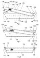
- the support member 104 When the panel 102 and support member 104 are fixed to a first side of an opening by a connector means 150 fastened to the support member 104 and secured to an anchor beam 151 (as shown in Figure 5) spanning the opening on the other side of the building 152, the support member 104 is pulled away from the front panel 106 until the plates 142, 144 of the support member 104 are engaged with the underside of the rims 120, 124, respectively, to press the rim portions against the surround of the opening being covered by the closure.
- the present invention is not restricted to a particular way of securing the security closure to the opening of the building and any convenient anchor and connecting means can be employed. However, a particularly advantageous securing system is described in the second set of embodiments described hereinafter.
- pins 146 and 148 are sufficiently shorter than shown in Figures 2 to 4 then it becomes possible to slide the support beam 14 from one aperture to another whilst the plates 142 and 144 are retained by the rims 120, 124.
- the support member can be moved parallel to the front face 106 of the panel 102 until the desired position has been found whereupon the second elongate beam 134 can be released to allow the pins to extend into another pair of opposed apertures.
- Figure 6 shows a stack of panels 102 in which the support beams 104 have been removed. This removal and the outwardly turned side walls 110, 112, 114, 116 provide particularly convenient and compact storage of the panels 102.
- a retaining member 210 comprises a plate section 212 made from steel. On inner side of the plate section 212 a housing 214 is formed. An opening in the plate section 212 is located above the housing 214.
- the housing 214 comprises side walls 215 extending perpendicularly from the plate section 212 and an end wall 216 extending between the side walls 212 parallel with the plate section. The end wall 216 has an opening aligned with the opening in the plate section 212.
- a movable plate 218 is mounted across the housing 214 between the end wall 216 and the plate section 212.
- the movable plate 218 is movable between a release position parallel with the plate section 212 and a gripping position where one end of the movable plate 18 is moved towards the plate section 212.
- the movable plate 218 has an opening aligned with the opening in the plate section 212 when the movable plate 218 is in the release position.
- the movable plate 218 being biased by spring 220 into the gripping position.
- a bar 222 is sized to fit closely through said three openings.
- One end of the bar 222 can be pushed through all three openings from the outer side of the plate section 212, or through the opening in the end wall 216 of the housing 214.
- the openings in the fixed plates 212, 216 can be made much larger as the fixed plates 212, 210 are not necessary for the gripping function of the retaining member 210, but greater movement of the movable plate 218 would be required in these circumstances.
- the movable plate 218 When the bar 222 is inserted through the openings, the movable plate 218 attempts to return to its gripping position.
- the edges 219 of the opening in the movable plate 218 frictionally engage the bar 222 to prevent movement of the bar 222 back out of the openings (in the direction of the arrow shown in Figure 8).
- a slot is provided in the plate section 212, through which a push member 226 is insertable (as shown in Figure 9).
- the push member 226 abuts against the end of the movable plate 218 on the end distant from the spring 220 when inserted through the slot.
- the push member 226 is pushed it applies a force to the said distant end of the movable plate to counter the biasing force provided by the spring 220.
- the movable plate 218 is thus moved to its release position.
- the bar 222 can then be withdrawn from the openings.
- the push member 226 is then removed from the slot.
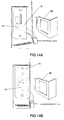
- the end of the movable plate 218 on which the spring 220 acts is directly accessible (as shown in Figure 11).
- the spring 220 is mounted on security bolt 221. This prevents compression of the spring 220 unless the bolt is undone. This stops spring 220 compression even if the bolt is hit by a hammer or otherwise forced.
- a security closure 230 is secured over a window, or other opening, of the building 232.
- a first retaining member 210 is fitted onto a support beam 228 of the security closure 230.
- the support beam 228 is secured in the rim of the security closure 230 between preset positions.
- the first retaining means 210 is slidable along the support beam 228.
- One end of the bar 222 is inserted into the openings of the retaining member 210 from the direction of the end wall of the housing 214, i.e. outwardly from the building.
- the other end of the bar 222 is inserted through a hole in the window of the building 232.
- the other end of the bar 222 is similarly inserted into another retaining member 210, inwardly to the building 232.
- the second retaining member 210 is mounted on a support structure 231 mounted in the interior of the building 232.
- the bar 222 is pushed right through second retaining member 210 to extend inwardly to the building.
- a tensioning device 234 is used (if required) to pull the said other end of the bar 222 inwardly to the building. This pulling secures the security closure 230 onto the building 232 by clamping the building 232 between the security closure 230 and the support structure 231.
- the ends of the anchor bar 222 are not threaded and so the tensioning device 234 advantageously does not damage such threaded sections.
- the retaining members 210 are both arranged so that the movable plate 218 of each of the retaining members 210 prevents removal of the bar 222 from the respective retaining member 210 in the direction towards the window. The arrangement thus prevents any slack being generated between the security closure 230 and the support structure 231.
- the only way to release the bar 222 is to undo the security bolt 221 and then compress spring 220 on the second retaining member 210. No push member 226 can be inserted through the slot of the first mentioned retaining member 210 because of the security closure 230.
- the security closure 230 is securely mounted across an opening in a very quick and easy manner.
- the security closure cannot be released as soon as the other end of the bar 222 is inserted into the second retaining means 210.
- a quick release/fitting is only required on one end of the anchor bar.
- the retaining member 210 is only fitted on one end of the anchor bar. The other end of the bar is then fixed in another manner.
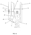
- Figure 12 and Figure 13 show a detail of a security closure with an emergency release mechanism according to the present invention fitted over an opening, such as a window, in the wall of the building 16.
- the panel 10 is normally formed from sheet metal but may be formed from other suitable materials.
- the panel 10 has a circumferential side wall 11. The circumference of the side wall 11 is arranged to completely surround the opening in the building 16.
- the security closure of the illustrated embodiment is fitted onto the building 16 by a bracing arrangement between a support beam 22 of the security closure extending across the opening on one side of the wall of the building 16 braced to an interior beam 15 extending across the opening on the opposite surface of the wall of the building 16.
- the support beam 22 is connected to the interior beam 15 by means of stud and nut arrangement 14.
- Alternative means of securing the support member 22 in relation to the opening could also be used, for example those disclosed above.
- the support beam 22 extends completely across the opening, but embodiments where the support beam 22 only extends partially across the opening or forms a brace between the opposed edges of the opening are also with the scope of the invention.
- the support beam 22 thus provides a fixed support for the panel 10.
- the panel 10 is securable to the support beam 22 in two positions.
- the panel 10 is releasably secured to the support beam 22 by the releasable securing means generally designated 18.
- the releasable securing means 18 comprises a lever bracket 19 and a connecting anchor 20.
- the lever bracket 19 is mounted on the interior surface of the panel 10.
- the connecting anchor 20 extends through the support beam 22 towards the interior surface of the panel 10.
- the connecting anchor 20 is held by the lever bracket 19 by engagement of the lever 21 on the connecting anchor 20.
- the lever 21 is disengaged from the connecting anchor 20
- the panel is movable to the position shown in Figure 13 (the "release position") where the connecting anchor 20 is removable from the lever bracket 19.
- the release mechanism on the support member 22 rather than on the interior of the panel 10.
- the panel 10 is also connected to the support member 22 by the hinged fixing means generally designated 24.
- a housing portion of the hinged fixing means 24 is shown connected to the circumferential side wall 11 by means of a security bolt 27.
- the hinged fixing means 24 could be secured to the side wall or panel in other ways, for example as shown in our aforementioned earlier patent applications.
- a second part of the hinge fixing means 24 is connected to the support member 22.
- the housing portion is connected to the second portion by pivot 25 about which the housing portion and the second portion an pivot with respect to one another along an axis extending generally parallel to the wall of the building 16.
- the second portion of the hinged fixing means 24 is fitted to the support member 22 by means of a pivot 26 which allows pivoting movement of the second portion about an axis parallel to but spaced from the first said axis.
- the panel 10 could pivot simply with the first mentioned axis, the illustrated embodiment is preferred as it allows movement of the panel 10 away from the wall before the panel 10 pivots. This allows a smoother pivoting motion of the panel 10.
- the panel 10 can pivot about the hinged fixing means 24 into the position shown in Figure 13.
- a person inside the building could then release the panel 10 and attract the attention of the emergency services from the window. If the height of the window was relatively small it would even be possible for a person to jump from the window. If the height was greater it would be possible for a ladder to be provided to the window or for the person to jump onto a safety mattress. However, this cannot be seen as an emergency escape as there would not normally be provided a means to travel from the opening/window to ground level.
- hinged fixing means 24 will be fitted to the top or side edge of a panel 10 when the security closure is considered in relation to the building 16.
- the lever 21 is normally operated via a handle mechanism 30.
- Visual indication means are normally provided to show whether or not the handle has been actuated. This provides ready indication whether or not the window has been released by an unauthorised personnel.
- the releasable securing means 18, may be biased so that the anchor bar 20 cannot be re-secured in the lever bracket 19 without disassembly of the releasable securing means 18.
- the panel 10 will be fitted to two support members 22, each having a hinged fixing means 24 along the same edge as the panel 10. Whilst it is not always necessary for each support member to have a releasable securing means 18, it is preferred if each supporting member 22 is so linked to the panel 10. In cases where each supporting member 22 is connected to the panel 10 via a releasable securing means 18, all of the releasable securing means 18 can be operated by the same handle 30 as shown in Figure 15.
- the handle 30 can be positioned anywhere on the interior surface of the panel 10. Thus, in any particular installation, the position of the handle can be determined so that the releasable securing means 18 can be transferred to its release position, through the window from inside the building 16.
Description
- This invention relates to a security closure for use in covering openings in a building, for example windows or the like.
- If a building is left vacant for more than a short period of time, for example to carry out renovation works, it becomes vulnerable to people breaking into the building for the purposes of theft squatting or vandalism. The normal windows of a building do not provide a high degree of security so it is known to cover the windows to make it more difficult to enter into the building.
- A rudimentary way of covering a window is to fasten a wooden board over the outside of the window but this is relatively easy to remove by someone determined to enter the building.
- A more secure closure for a window is disclosed in UK Patent GB-B-2,160,248 in which a security closure is formed as a metal panel having a circumferential side wall with an inwardly turned rim. The panel is held with the rim against the outside of the opening by means of support beams captively retained by the inwardly turned rim of the panel and which are tied by connecting rods to anchor beams spanning the opening on the inside of the building. The connecting rod is tightened so the wall of the building around the opening is clamped between the panel and the anchor beam.
- In order to allow the connecting tie to pass through a convenient position in the opening, for example through an open light in the window, the panel is arranged so that the support beam can slide parallel to the face of the panel whilst being retained by the rim and the support beam is designed so that the connecting tie is slidable along the support and anchor beams thereby allowing the connecting tie to be located at most positions within the plane of the panel. However, such nut and bolt connections are difficult to secure quickly. In some instances the panel slips from position before the connection can be secured. This presents particular difficulties when securing closures on windows on the upper levels of buildings where the panel could fall from the building or unbalance a worker which is particularly hazardous with heavy security closures.
- There are a number of disadvantages associated with known security closures of this type, the principle one being that the support beams are prone to sliding out of the desired position as the panel is offered to the building unless great care is taken. This problem is particularly acute with large panels where the support beam is relatively heavy and can, when falling under its own weight, become wedged if it rotates relative to the panel into a skewed position.
- The present invention includes embodiments which seek to address the above disadvantages.
- One of the benefits of the systems presently used is that personnel within the building should not be able to remove a panel once installed. This reduces the instances that the building is left unsecured by the panel removal by unauthorised personnel.
- One major disadvantage with the presently used panels and those described above is that the panels are not easily removed from either inside or outside the building. This disadvantage is most apparent when there is a fire or other emergency in the building. In these circumstances it may be that a personnel become trapped inside rooms of the buildings without access to the exits from the building. Of course, as the personnel will not be able to remove the panel from the inside of the building and emergency services cannot easily remove the panel from the outside of the building, personnel can become fatally trapped within the building.
- The present invention seeks to provide a panel with an emergency release mechanism which allows at least some of the panels on a building to be released in the event of emergencies.
- Preferably, the emergency release will indicate whether or not it has been used thus preventing unauthorised tampering with the emergency release system.
- According to the present invention there is provided a security closure for covering an opening in a building comprising a panel with a circumferential sidewall, and a support member securable to extend across the opening in fixed relation thereto, the support member being releasably securable to the interior of the panel away from one edge thereof by releasable securing means to secure the panel over the opening with the sidewall abutting the building, and the support member being fixed at said one edge by hinged fixing means which allows the panel to pivot substantially along said one edge away from the opening when the support member is released from said releasable securing means.
- As the support bar is only permanently fixed at one end to the panel the panel can be hinged away from the opening by means of the pivot provided on the end of the support member fixed to the edge of the panel.
- In many cases the security closure will be provided with a plurality of the support members.
- In the preferred embodiment of the invention, the hinged fixing means is fixed to the circumferential sidewall and, advantageously, the hinged fixing means provides movement of the panel away from the building prior to the said pivoting to allow a smooth movement of the panel even though the pivot axis is out of the plane of the wall. This prior movement may be provided by a second pivot provided in the hinged fixing means with an axis substantially parallel to the first-mentioned pivot and spaced along the support member further from the said one edge than the first-mentioned pivot.
- In the preferred embodiment of the invention, the releasable securing means of the or each support member comprises a connecting anchor connecting the support member to a panel fixing mounted on the panel. The panel fixing may comprise a lever bracket which comprises a housing mounted on the interior of the panel with an opening on the interior side of the housing through which opening the connecting anchor is arranged to fit, the connecting anchor being fitted through said opening and engaged by a lever in the housing when the support member is secured by the releasable securing means, and the connecting anchor being dis-engaged from the lever and being removable from the housing when the support member is released from releasable securing means.
- Preferably, the or each releasable securing means is releasable by means of release handle operatively connected to the or each securing means, the release handle being mounted on the interior of the panel.
- The handle is advantageously positioned to be easily accessible from inside the building. This is accomplished by the handle position being independent of the releasable securing means position. This is particularly useful when the panel is installed over a window which has lights through which the handle can be made accessible. The independent positioning of the handle means that the fixing points of the support members fixings can be optimised in the panel as the fixings do not need to be accessible to any user.
- It is advantageous if an indicator is provided which indicates whether or not the releasable securing means have been released.
- The present invention will now be described, by way of example only, with reference to Figs 12 to 16 of the accompanying drawings of which:
- Figures 1 to 6 show a first set of embodiments relating to the fixing of a support member in the panel which is not an embodiment of the claimed invention;
- Figure 1 is a schematic perspective view of a security closure;
- Figures 2 to 4 are schematic cross-sectional views of the security closure in the direction A-A of Figure 1 showing the stages of insertion and engagement of the support member with the panel of Figure 1; Figure 5 is a sectional view of a security closure fitted to a building;
- Figure 6 shows a stack of the security closures with the support members removed;
- Figures 7 to 11 show a second set of embodiments which relate to the fixing of the security closure on to the building which is not an embodiment of the claimed invention;
- Figure 7 shows a perspective view of a retaining member;
- Figure 8 shows the securing means in a gripping position;
- Figure 9 shows the securing means of Fig. 8 in a release position;
- Figure 10 shows the securing means of the present invention securing a security closure over an window in a building;
- Figure 11 shows a sectional view along the line A-A of Fig. 10;
- Figures 12 to 16 show an embodiment of the security closure of the present invention fitted with an emergency release mechanism;
- Figure 12 shows a partial cross-section plain view through a security closure according to the present invention when mounted on a building in its secured position;
- Figure 13 shows the cross-sectional plain view of Figure 1 with the security closure in its released position;
- Figure 14a shows a view of a release catch of the present invention in a release position;
- Figure 14b shows a view of Figure 14a in a secure position;
- Figure 15 shows a rear internal view of a security closure according to the present invention;
- Figure 16 shows an alternative means of fixing the support member in the panel of the present invention.
-
- Referring to Figure 1, a security closure comprises a
panel 102 and an elongate,telescopic support member 104. - The
panel 102 is formed from a cut and folded sheet of galvanised steel. This embodiment has arectangular face 106 through which are punched an array of regularly spaced through-holes 108 which make ventilation and light available to the interior of a building to which thepanel 102 is applied without allowing access to thesupport beam 104 so as preserve the security of the closure. The panel has fourside wall portions rectangular front face 106. Theside walls face plate 106. The top of eachside wall portion shaped rim - Each
rim front face 106 which in use of the panel is placed in abutment with the portion of the building surrounding the opening to be closed. The innermost portion of each of therims 118 is in the form of a lip downwardly extendinglip 128 extending towards thefront face 106 parallel with therespective side wall - Each of the
side wall portions panel 102 is provided with a row of regularly spacedapertures 130 which constitute part of the interlocking means preventing lateral movements of thesupport member 104 as will be described in more detail later. - The
apertures 130 are generally rectangular with curved top and bottom edges and have their principal axes perpendicular to the plane of thefront face 106. - Referring now also to Figure 2, the
support member 104 is telescopic and comprises a firstelongate beam 132 of C-shaped cross section within which is received a secondelongate beam 134 of U-shaped cross section. - The
first beam 132 is in the form of a generally rectangular tube with an open channel orslot 136 in the uppermost face of thebeam 132. - A connector (not shown) can be inserted through the
slot 136 and fixed to thesupport member 104 by means of a captive locking mechanism (not shown), for example, retained within thesupport member 104 in known fashion. - The
second beam 134 has aplanar base 138 and a pair of opposed,parallel side walls 140 extending upwards at right angles to thebase 138. - The end of the
second beam 134 which projects from within thefirst beam 132 is capped with arectangular plate 142 which extends above theside walls 140. The end of the firstelongate beam 132 furthest away from theplate 142 is capped with a similarrectangular plate 144 which similarly extends above the secondelongate beam 132. - The ends of the first and second
elongate beams plates plates side beam 104 is parallel to theface plate 106 and the other twoside walls -
Cylindrical pins plates pins apertures 130 inside wall portions - The
base 138 of thesecond beam 134 is provided with acentral slot 150 which extends the length of the secondelongate beam 134. Ametal plate 152 is welded in position across the secondelongate beam 134 between theside walls 140 with a through-hole in theplate 152 forming a first anchor point for a first end of aspring 154. - The
base 138 of thefirst beam 132 has anupstanding tab 156 formed by punching through a portion of thebase 138 and dimensioned so it can move within thechannel 150 in thesecond beam 134. A through-hole is provided in thetab 156 to provide a second anchor point to the second end of thespring 154. - The
spring 154 urges theplate 152 and thetab 156 together thereby urging thefirst portion 134 to telescope out of thefirst portion 132 to the position as shown in Figure 2. Thesupport beam 104 can be shortened by pressing thesecond beam 134 into thefirst beam 132 by hand to the position as shown in Figure 3. When in this shortened configuration thesupport beam 104 can be placed within theside walls panel 102 beneath therims panel 102 in Figure 3. - The length and position of the
pins support beam 104 cannot be located beneath the rim unless thepins apertures 130 as shown in Figure 3. If thepin 148 is not aligned with one of theapertures 130 the length of thepin 148 is such as to prevent theplate 144 from getting close enough to thesidewall 116 to allow the plate to be received under therim portions - When the
pin 148 is aligned with anaperture 130 the other end of thesupport member 104 can likewise be aligned with an aperture directly opposite that in which thepin 148 has entered to allow theplate 142 to lie beneath therim - On then releasing the first and
second beams support beam 104 telescopes outwards under the action of thespring 154 to push theplates side walls support member 104 is now fixed in position within thepanel 102 which can now be moved without thesupport member 104 sliding from the selected position. - When the
panel 102 andsupport member 104 are fixed to a first side of an opening by a connector means 150 fastened to thesupport member 104 and secured to an anchor beam 151 (as shown in Figure 5) spanning the opening on the other side of thebuilding 152, thesupport member 104 is pulled away from thefront panel 106 until theplates support member 104 are engaged with the underside of therims - If the
pins support beam 14 from one aperture to another whilst theplates rims front face 106 of thepanel 102 until the desired position has been found whereupon the secondelongate beam 134 can be released to allow the pins to extend into another pair of opposed apertures. - Figure 6 shows a stack of
panels 102 in which the support beams 104 have been removed. This removal and the outwardly turnedside walls panels 102. - Turning now to the second set of embodiments shown in Figures 7 to 11, a retaining
member 210 comprises aplate section 212 made from steel. On inner side of the plate section 212 ahousing 214 is formed. An opening in theplate section 212 is located above thehousing 214. Thehousing 214 comprisesside walls 215 extending perpendicularly from theplate section 212 and anend wall 216 extending between theside walls 212 parallel with the plate section. Theend wall 216 has an opening aligned with the opening in theplate section 212. - A
movable plate 218 is mounted across thehousing 214 between theend wall 216 and theplate section 212. Themovable plate 218 is movable between a release position parallel with theplate section 212 and a gripping position where one end of themovable plate 18 is moved towards theplate section 212. - The
movable plate 218 has an opening aligned with the opening in theplate section 212 when themovable plate 218 is in the release position. Themovable plate 218 being biased byspring 220 into the gripping position. - A
bar 222 is sized to fit closely through said three openings. One end of thebar 222 can be pushed through all three openings from the outer side of theplate section 212, or through the opening in theend wall 216 of thehousing 214. Of course the openings in the fixedplates plates member 210, but greater movement of themovable plate 218 would be required in these circumstances. - When the
bar 222 is inserted through the openings, themovable plate 218 attempts to return to its gripping position. Theedges 219 of the opening in themovable plate 218 frictionally engage thebar 222 to prevent movement of thebar 222 back out of the openings (in the direction of the arrow shown in Figure 8). - A slot is provided in the
plate section 212, through which apush member 226 is insertable (as shown in Figure 9). Thepush member 226 abuts against the end of themovable plate 218 on the end distant from thespring 220 when inserted through the slot. When thepush member 226 is pushed it applies a force to the said distant end of the movable plate to counter the biasing force provided by thespring 220. Themovable plate 218 is thus moved to its release position. Thebar 222 can then be withdrawn from the openings. Thepush member 226 is then removed from the slot. - When the retaining
member 210 is used to secure theanchor bar 222 on the inside of the building, the end of themovable plate 218 on which thespring 220 acts is directly accessible (as shown in Figure 11). In order to prevent accidental or unauthorised release of the retainingmember 210, thespring 220 is mounted onsecurity bolt 221. This prevents compression of thespring 220 unless the bolt is undone. This stopsspring 220 compression even if the bolt is hit by a hammer or otherwise forced. - As shown in Figure 10, a
security closure 230 is secured over a window, or other opening, of thebuilding 232. A first retainingmember 210 is fitted onto asupport beam 228 of thesecurity closure 230. Thesupport beam 228 is secured in the rim of thesecurity closure 230 between preset positions. The first retaining means 210 is slidable along thesupport beam 228. One end of thebar 222 is inserted into the openings of the retainingmember 210 from the direction of the end wall of thehousing 214, i.e. outwardly from the building. - The other end of the
bar 222 is inserted through a hole in the window of thebuilding 232. The other end of thebar 222 is similarly inserted into another retainingmember 210, inwardly to thebuilding 232. Thesecond retaining member 210 is mounted on asupport structure 231 mounted in the interior of thebuilding 232. Thebar 222 is pushed right through second retainingmember 210 to extend inwardly to the building. Atensioning device 234 is used (if required) to pull the said other end of thebar 222 inwardly to the building. This pulling secures thesecurity closure 230 onto thebuilding 232 by clamping thebuilding 232 between thesecurity closure 230 and thesupport structure 231. The ends of theanchor bar 222 are not threaded and so thetensioning device 234 advantageously does not damage such threaded sections. - The retaining
members 210 are both arranged so that themovable plate 218 of each of the retainingmembers 210 prevents removal of thebar 222 from the respective retainingmember 210 in the direction towards the window. The arrangement thus prevents any slack being generated between thesecurity closure 230 and thesupport structure 231. - The only way to release the
bar 222 is to undo thesecurity bolt 221 and then compressspring 220 on thesecond retaining member 210. Nopush member 226 can be inserted through the slot of the first mentioned retainingmember 210 because of thesecurity closure 230. - Once tensioned the
security closure 230 is securely mounted across an opening in a very quick and easy manner. The security closure cannot be released as soon as the other end of thebar 222 is inserted into the second retaining means 210. - In other versions of the second set of embodiments (not shown) a quick release/fitting is only required on one end of the anchor bar. In these cases the retaining
member 210 is only fitted on one end of the anchor bar. The other end of the bar is then fixed in another manner. - The above described first and second sets of embodiments are included herein to fully set out the advantageous types of panel often used in conjunction with the security closure with emergency release mechanism described herein below.
- Figure 12 and Figure 13 show a detail of a security closure with an emergency release mechanism according to the present invention fitted over an opening, such as a window, in the wall of the
building 16. Thepanel 10 is normally formed from sheet metal but may be formed from other suitable materials. Thepanel 10 has acircumferential side wall 11. The circumference of theside wall 11 is arranged to completely surround the opening in thebuilding 16. - The security closure of the illustrated embodiment is fitted onto the
building 16 by a bracing arrangement between asupport beam 22 of the security closure extending across the opening on one side of the wall of thebuilding 16 braced to aninterior beam 15 extending across the opening on the opposite surface of the wall of thebuilding 16. In the illustrated embodiment, thesupport beam 22 is connected to theinterior beam 15 by means of stud andnut arrangement 14. Alternative means of securing thesupport member 22 in relation to the opening could also be used, for example those disclosed above. Normally thesupport beam 22 extends completely across the opening, but embodiments where thesupport beam 22 only extends partially across the opening or forms a brace between the opposed edges of the opening are also with the scope of the invention. - The
support beam 22 thus provides a fixed support for thepanel 10. Thepanel 10 is securable to thesupport beam 22 in two positions. - The
panel 10 is releasably secured to thesupport beam 22 by the releasable securing means generally designated 18. The releasable securing means 18 comprises alever bracket 19 and a connectinganchor 20. Thelever bracket 19 is mounted on the interior surface of thepanel 10. The connectinganchor 20 extends through thesupport beam 22 towards the interior surface of thepanel 10. In the position shown in Figure 12 where the releasable fixing means 18 secures thepanel 10 to thesupport member 22, the connectinganchor 20 is held by thelever bracket 19 by engagement of thelever 21 on the connectinganchor 20. When thelever 21 is disengaged from the connectinganchor 20, the panel is movable to the position shown in Figure 13 (the "release position") where the connectinganchor 20 is removable from thelever bracket 19. Of course, it would be possible to arrange the release mechanism on thesupport member 22 rather than on the interior of thepanel 10. - The
panel 10 is also connected to thesupport member 22 by the hinged fixing means generally designated 24. A housing portion of the hinged fixing means 24 is shown connected to thecircumferential side wall 11 by means of asecurity bolt 27. Alternatively, the hinged fixing means 24 could be secured to the side wall or panel in other ways, for example as shown in our aforementioned earlier patent applications. A second part of the hinge fixing means 24 is connected to thesupport member 22. The housing portion is connected to the second portion bypivot 25 about which the housing portion and the second portion an pivot with respect to one another along an axis extending generally parallel to the wall of thebuilding 16. - In the illustrated embodiment, the second portion of the hinged fixing means 24 is fitted to the
support member 22 by means of apivot 26 which allows pivoting movement of the second portion about an axis parallel to but spaced from the first said axis. Whilst thepanel 10 could pivot simply with the first mentioned axis, the illustrated embodiment is preferred as it allows movement of thepanel 10 away from the wall before thepanel 10 pivots. This allows a smoother pivoting motion of thepanel 10. - When the releasable securing means 18 has been moved into its release position the
panel 10 can pivot about the hinged fixing means 24 into the position shown in Figure 13. As will be appreciated, a person inside the building could then release thepanel 10 and attract the attention of the emergency services from the window. If the height of the window was relatively small it would even be possible for a person to jump from the window. If the height was greater it would be possible for a ladder to be provided to the window or for the person to jump onto a safety mattress. However, this cannot be seen as an emergency escape as there would not normally be provided a means to travel from the opening/window to ground level. - Normally the hinged fixing means 24 will be fitted to the top or side edge of a
panel 10 when the security closure is considered in relation to thebuilding 16. - The
lever 21 is normally operated via ahandle mechanism 30. Visual indication means are normally provided to show whether or not the handle has been actuated. This provides ready indication whether or not the window has been released by an unauthorised personnel. Also the releasable securing means 18, may be biased so that theanchor bar 20 cannot be re-secured in thelever bracket 19 without disassembly of the releasable securing means 18. - In many instances, the
panel 10 will be fitted to twosupport members 22, each having a hinged fixing means 24 along the same edge as thepanel 10. Whilst it is not always necessary for each support member to have a releasable securing means 18, it is preferred if each supportingmember 22 is so linked to thepanel 10. In cases where each supportingmember 22 is connected to thepanel 10 via a releasable securing means 18, all of the releasable securing means 18 can be operated by thesame handle 30 as shown in Figure 15. Thehandle 30 can be positioned anywhere on the interior surface of thepanel 10. Thus, in any particular installation, the position of the handle can be determined so that the releasable securing means 18 can be transferred to its release position, through the window from inside thebuilding 16. - An alternative way that the
support beam 22 could be fitted is shown in Figure 16. This fixing provides particularly simple way to fix the supporting member. - It should be borne in mind that it remains important that no way to release the
panel 10 is available from the exterior of the building when thepanel 10 is in use. Accordingly, any bolts which extend through thepanel 10 will normally be security bolts which cannot be removed in the absence of specially designed tools. - It will no doubt be appreciated that in most installations numerous panels are fitted to the building. It will normally only be necessary to fit the
panels 10 of the present invention to a limited number of the openings in thebuilding 16. Of course, these panels can be fitted to other openings apart from windows, such as doors, provided that entry and exit through the opening is not normally required. - Of course the various fixing arrangements described in the first set of embodiments, the second set of embodiments and the embodiments of the invention may all be used in conjunction with one another as will readily apparent to the skilled person, though it is not preferred to have an emergency release support bar fitted to the same panel as the support bars of the first set of embodiments.
Claims (10)
- A security closure for covering an opening in a building (16) comprising a panel (10) with a circumferential sidewall (11), and a support member (22) securable to extend across the opening in fixed relation thereto, characterised in that the support member (22) is releasably securable to the interior of the panel (10) away from one edge thereof by releasable securing means (18) to secure the panel (10) over the opening (16) with the sidewall abutting the building, and the support member (22) being fixed at said one edge by hinged fixing means (24) disposed internally of the panel which allows the panel (10) to pivot substantially along said one edge away from the opening when the support member (22) is released from said releasable securing means (18).
- The security closure according to claim 1, wherein the hinged fixing means (24) is fixed to the circumferential sidewall (11).
- The security closure according to claim 1 or claim 2, wherein the hinged fixing means (24) provides movement of the panel (10) away from the building prior to the said pivoting.
- The security closure according to claim 3, wherein said prior movement is provided by a second pivot (26) provided in the hinged fixing means (24) with an axis substantially parallel to the first-mentioned pivot (25) and spaced along the support member (22) further from the said one edge than the first-mentioned pivot (25).
- The security closure according to any one of the preceding claims, further including a plurality of the support members (22).
- A security closure according to any one of the preceding claims, wherein the releasable securing means (18) of the or each support member (22) comprises a connecting anchor (20) connecting the support member (22) to a panel fixing mounted on the panel (10).
- A security closure according to claim 6, wherein the panel (10) fixing comprises a lever bracket (19) which comprises a housing mounted on the interior of the panel with an opening on the interior side of the housing through which opening the connecting anchor (20) is arranged to fit, the connecting anchor (20) being fitted through the opening and engaged by a lever (21) in the housing when the support member (22) is secured by the releasable securing means (18), and the connecting anchor (20) being dis-engaged from the lever (21) and being removable from the housing when the support member (22) is released from releasable securing means (18).
- The security closure according to any one of the preceding claims, wherein the or each releasable securing means (18) is releasable by means of release handle (30) operatively connected to the or each securing means (18); the release handle (30) being mounted on the interior of the panel (10).
- A security closure according to claim 8, wherein the position of the handle (30) is independent of the position of the releasable fixing means (18), and optionally the handle position can be varied depending upon the installation.
- The security closure according to any one of the preceding claims, wherein an indicator is provided which indicates whether or not the releasable securing means (18) have been released.
Applications Claiming Priority (6)
| Application Number | Priority Date | Filing Date | Title |
|---|---|---|---|
| GB9503458 | 1995-02-22 | ||
| GB9503447 | 1995-02-22 | ||
| GBGB9503458.3A GB9503458D0 (en) | 1995-02-22 | 1995-02-22 | A method and apparatus for securing a security closure |
| GBGB9503447.6A GB9503447D0 (en) | 1995-02-22 | 1995-02-22 | Security closure |
| GB9524096 | 1995-11-24 | ||
| GBGB9524096.6A GB9524096D0 (en) | 1995-11-24 | 1995-11-24 | Security enclosure |
Publications (2)
| Publication Number | Publication Date |
|---|---|
| EP0728899A1 EP0728899A1 (en) | 1996-08-28 |
| EP0728899B1 true EP0728899B1 (en) | 2001-09-05 |
Family
ID=27267596
Family Applications (1)
| Application Number | Title | Priority Date | Filing Date |
|---|---|---|---|
| EP96301154A Expired - Lifetime EP0728899B1 (en) | 1995-02-22 | 1996-02-21 | Security closure |
Country Status (4)
| Country | Link |
|---|---|
| US (1) | US5832671A (en) |
| EP (1) | EP0728899B1 (en) |
| DE (1) | DE69614897T2 (en) |
| ES (1) | ES2163586T3 (en) |
Families Citing this family (14)
| Publication number | Priority date | Publication date | Assignee | Title |
|---|---|---|---|---|
| GB2311552A (en) * | 1996-03-26 | 1997-10-01 | Malcolm Mawson | Protective cover for a door or window |
| US6532704B2 (en) | 2001-05-25 | 2003-03-18 | Michael Guynn Hart | Board-up-buddy |
| GB2393993A (en) * | 2002-10-10 | 2004-04-14 | Radcom Security Services Ltd | Security closure for unoccupied premises |
| CA2601521A1 (en) * | 2005-02-15 | 2006-08-24 | Warm Springs Composite | Fire door |
| US9189934B2 (en) | 2005-09-22 | 2015-11-17 | Rsi Video Technologies, Inc. | Security monitoring with programmable mapping |
| GB0601815D0 (en) * | 2006-01-30 | 2006-03-08 | Vps Holdings Ltd | Security door apparatus |
| GB0601816D0 (en) * | 2006-01-30 | 2006-03-08 | Vps Holdings Ltd | Alarm system |
| US8745926B2 (en) * | 2010-12-23 | 2014-06-10 | Fabio Giovanni De Domenico | Frameless access panel with latch member |
| US9495849B2 (en) | 2011-08-05 | 2016-11-15 | Rsi Video Technologies, Inc. | Security monitoring system |
| US8756883B2 (en) | 2011-11-07 | 2014-06-24 | Door & Window Guard Systems, Inc. | Assembly and method for securing a door opening or other opening of a building structure |
| US8656664B2 (en) | 2011-11-07 | 2014-02-25 | Door & Window Guard Systems, Inc. | Assembly and method for securing an opening of a building structure |
| US9495845B1 (en) | 2012-10-02 | 2016-11-15 | Rsi Video Technologies, Inc. | Control panel for security monitoring system providing cell-system upgrades |
| US9472067B1 (en) | 2013-07-23 | 2016-10-18 | Rsi Video Technologies, Inc. | Security devices and related features |
| US9963929B2 (en) | 2016-08-29 | 2018-05-08 | Door & Window Guard Systems, Inc. | Assembly and method for securing a door opening or other opening of a building structure |
Family Cites Families (10)
| Publication number | Priority date | Publication date | Assignee | Title |
|---|---|---|---|---|
| GB812916A (en) * | 1955-04-25 | 1959-05-06 | Limit Engineering Group Ltd | Improvements in or relating to locking devices for telescopic pedestals and the like |
| GB898841A (en) * | 1960-06-28 | 1962-06-14 | Mortimer Ernesto Esquivel | A locking device |
| GB1230843A (en) * | 1968-08-28 | 1971-05-05 | ||
| GB2160248B (en) * | 1984-06-14 | 1987-04-23 | Jolpine Ltd | Security closure |
| IE57110B1 (en) * | 1985-11-12 | 1992-04-22 | Valentine Patrick Galvin | Improvements in security grilles |
| WO1989000637A1 (en) * | 1987-07-17 | 1989-01-26 | Watt Ronald W | Security closure |
| GB2247269A (en) * | 1991-01-24 | 1992-02-26 | Watt Ronald W | A security door assembly |
| TW205087B (en) * | 1991-12-13 | 1993-05-01 | Uitimate Support Systems Inc | |
| GB2268531A (en) * | 1992-06-19 | 1994-01-12 | No Entry Limited | Security panel |
| GB2270336A (en) * | 1992-08-15 | 1994-03-09 | Pioneer Security Systems Limit | Security cover |
-
1996
- 1996-02-20 US US08/603,314 patent/US5832671A/en not_active Expired - Lifetime
- 1996-02-21 DE DE69614897T patent/DE69614897T2/en not_active Expired - Lifetime
- 1996-02-21 EP EP96301154A patent/EP0728899B1/en not_active Expired - Lifetime
- 1996-02-21 ES ES96301154T patent/ES2163586T3/en not_active Expired - Lifetime
Also Published As
| Publication number | Publication date |
|---|---|
| DE69614897D1 (en) | 2001-10-11 |
| ES2163586T3 (en) | 2002-02-01 |
| DE69614897T2 (en) | 2003-01-16 |
| EP0728899A1 (en) | 1996-08-28 |
| US5832671A (en) | 1998-11-10 |
Similar Documents
| Publication | Publication Date | Title |
|---|---|---|
| EP0728899B1 (en) | Security closure | |
| US4817334A (en) | Window bar security system | |
| EP1552087B1 (en) | A system for screening off and a method of mounting thereof | |
| US3949834A (en) | Safety net and adjustable support therefor | |
| US20170284153A1 (en) | Retractable Barrier System | |
| US5911660A (en) | Storm window panel | |
| US10214948B2 (en) | Door barricade | |
| US20080222972A1 (en) | Truss gusset plate and anchor safety system | |
| GB2160248A (en) | Security closure | |
| EP0976324B1 (en) | Device for the fixing of bait stations at ground level | |
| US5937593A (en) | Security closure | |
| US5466022A (en) | Safety cable lock for knob-operated door | |
| US4938154A (en) | Security closure | |
| GB2592433A (en) | Hop-up scaffold bracket | |
| EP0303414B1 (en) | A post and rail assembly | |
| US5842539A (en) | Fire escape assembly | |
| GB2571771A (en) | Fence bracket | |
| GB2208171A (en) | Security closure | |
| US4751885A (en) | Security safe | |
| US7565776B2 (en) | Escape mechanism for hurricane shutters | |
| US20090217604A1 (en) | Mullion base plate extension | |
| US5345729A (en) | Support for tamper proof securing light fixture on suspended ceiling panel | |
| AU585255B2 (en) | Retaining assemblies | |
| JP3251416B2 (en) | Temporary doors for elevator openings | |
| GB2261461A (en) | Barrier apparatus for use in protecting empty unused buildings against vandals |
Legal Events
| Date | Code | Title | Description |
|---|---|---|---|
| PUAI | Public reference made under article 153(3) epc to a published international application that has entered the european phase |
Free format text: ORIGINAL CODE: 0009012 |
|
| AK | Designated contracting states |
Kind code of ref document: A1 Designated state(s): DE ES FR GB IE IT NL |
|
| 17P | Request for examination filed |
Effective date: 19970209 |
|
| 17Q | First examination report despatched |
Effective date: 19981201 |
|
| GRAG | Despatch of communication of intention to grant |
Free format text: ORIGINAL CODE: EPIDOS AGRA |
|
| GRAG | Despatch of communication of intention to grant |
Free format text: ORIGINAL CODE: EPIDOS AGRA |
|
| GRAH | Despatch of communication of intention to grant a patent |
Free format text: ORIGINAL CODE: EPIDOS IGRA |
|
| GRAH | Despatch of communication of intention to grant a patent |
Free format text: ORIGINAL CODE: EPIDOS IGRA |
|
| GRAA | (expected) grant |
Free format text: ORIGINAL CODE: 0009210 |
|
| AK | Designated contracting states |
Kind code of ref document: B1 Designated state(s): DE ES FR GB IE IT NL |
|
| PG25 | Lapsed in a contracting state [announced via postgrant information from national office to epo] |
Ref country code: NL Free format text: LAPSE BECAUSE OF FAILURE TO SUBMIT A TRANSLATION OF THE DESCRIPTION OR TO PAY THE FEE WITHIN THE PRESCRIBED TIME-LIMIT Effective date: 20010905 Ref country code: IT Free format text: LAPSE BECAUSE OF FAILURE TO SUBMIT A TRANSLATION OF THE DESCRIPTION OR TO PAY THE FEE WITHIN THE PRESCRIBED TIME-LIMIT;WARNING: LAPSES OF ITALIAN PATENTS WITH EFFECTIVE DATE BEFORE 2007 MAY HAVE OCCURRED AT ANY TIME BEFORE 2007. THE CORRECT EFFECTIVE DATE MAY BE DIFFERENT FROM THE ONE RECORDED. Effective date: 20010905 |
|
| REF | Corresponds to: |
Ref document number: 69614897 Country of ref document: DE Date of ref document: 20011011 |
|
| REG | Reference to a national code |
Ref country code: IE Ref legal event code: FG4D |
|
| REG | Reference to a national code |
Ref country code: GB Ref legal event code: IF02 |
|
| NLV1 | Nl: lapsed or annulled due to failure to fulfill the requirements of art. 29p and 29m of the patents act | ||
| REG | Reference to a national code |
Ref country code: ES Ref legal event code: FG2A Ref document number: 2163586 Country of ref document: ES Kind code of ref document: T3 |
|
| ET | Fr: translation filed | ||
| PG25 | Lapsed in a contracting state [announced via postgrant information from national office to epo] |
Ref country code: IE Free format text: LAPSE BECAUSE OF NON-PAYMENT OF DUE FEES Effective date: 20020221 |
|
| PLBE | No opposition filed within time limit |
Free format text: ORIGINAL CODE: 0009261 |
|
| STAA | Information on the status of an ep patent application or granted ep patent |
Free format text: STATUS: NO OPPOSITION FILED WITHIN TIME LIMIT |
|
| 26N | No opposition filed | ||
| REG | Reference to a national code |
Ref country code: IE Ref legal event code: MM4A |
|
| PGFP | Annual fee paid to national office [announced via postgrant information from national office to epo] |
Ref country code: FR Payment date: 20110315 Year of fee payment: 16 |
|
| PGFP | Annual fee paid to national office [announced via postgrant information from national office to epo] |
Ref country code: ES Payment date: 20110302 Year of fee payment: 16 Ref country code: GB Payment date: 20110225 Year of fee payment: 16 Ref country code: DE Payment date: 20110428 Year of fee payment: 16 |
|
| GBPC | Gb: european patent ceased through non-payment of renewal fee |
Effective date: 20120221 |
|
| REG | Reference to a national code |
Ref country code: FR Ref legal event code: ST Effective date: 20121031 |
|
| REG | Reference to a national code |
Ref country code: DE Ref legal event code: R119 Ref document number: 69614897 Country of ref document: DE Effective date: 20120901 |
|
| PG25 | Lapsed in a contracting state [announced via postgrant information from national office to epo] |
Ref country code: GB Free format text: LAPSE BECAUSE OF NON-PAYMENT OF DUE FEES Effective date: 20120221 Ref country code: FR Free format text: LAPSE BECAUSE OF NON-PAYMENT OF DUE FEES Effective date: 20120229 |
|
| PG25 | Lapsed in a contracting state [announced via postgrant information from national office to epo] |
Ref country code: DE Free format text: LAPSE BECAUSE OF FAILURE TO SUBMIT A TRANSLATION OF THE DESCRIPTION OR TO PAY THE FEE WITHIN THE PRESCRIBED TIME-LIMIT Effective date: 20120901 |
|
| REG | Reference to a national code |
Ref country code: ES Ref legal event code: FD2A Effective date: 20130708 |
|
| PG25 | Lapsed in a contracting state [announced via postgrant information from national office to epo] |
Ref country code: ES Free format text: LAPSE BECAUSE OF NON-PAYMENT OF DUE FEES Effective date: 20120222 |