EP0728554B1 - Apparatus for quickly cutting of steel using oxygen in continuous steel casting plants - Google Patents
Apparatus for quickly cutting of steel using oxygen in continuous steel casting plants Download PDFInfo
- Publication number
- EP0728554B1 EP0728554B1 EP19950102728 EP95102728A EP0728554B1 EP 0728554 B1 EP0728554 B1 EP 0728554B1 EP 19950102728 EP19950102728 EP 19950102728 EP 95102728 A EP95102728 A EP 95102728A EP 0728554 B1 EP0728554 B1 EP 0728554B1
- Authority
- EP
- European Patent Office
- Prior art keywords
- oxygen
- jet
- cutting
- pressure
- speed
- Prior art date
- Legal status (The legal status is an assumption and is not a legal conclusion. Google has not performed a legal analysis and makes no representation as to the accuracy of the status listed.)
- Expired - Lifetime
Links
- 238000005520 cutting process Methods 0.000 title claims description 40
- QVGXLLKOCUKJST-UHFFFAOYSA-N atomic oxygen Chemical compound [O] QVGXLLKOCUKJST-UHFFFAOYSA-N 0.000 title claims description 21
- 239000001301 oxygen Substances 0.000 title claims description 20
- 229910052760 oxygen Inorganic materials 0.000 title claims description 20
- 229910000831 Steel Inorganic materials 0.000 title claims description 7
- 239000010959 steel Substances 0.000 title claims description 7
- 238000005266 casting Methods 0.000 title claims description 6
- 238000000034 method Methods 0.000 claims 1
- 238000010438 heat treatment Methods 0.000 description 9
- 239000002893 slag Substances 0.000 description 9
- 238000006243 chemical reaction Methods 0.000 description 6
- 241000196324 Embryophyta Species 0.000 description 3
- 230000015572 biosynthetic process Effects 0.000 description 3
- 239000007789 gas Substances 0.000 description 3
- XEEYBQQBJWHFJM-UHFFFAOYSA-N Iron Chemical compound [Fe] XEEYBQQBJWHFJM-UHFFFAOYSA-N 0.000 description 2
- UQSXHKLRYXJYBZ-UHFFFAOYSA-N Iron oxide Chemical compound [Fe]=O UQSXHKLRYXJYBZ-UHFFFAOYSA-N 0.000 description 2
- 238000004519 manufacturing process Methods 0.000 description 2
- 239000000463 material Substances 0.000 description 2
- 238000007789 sealing Methods 0.000 description 2
- 240000005528 Arctium lappa Species 0.000 description 1
- 235000003130 Arctium lappa Nutrition 0.000 description 1
- 235000008078 Arctium minus Nutrition 0.000 description 1
- 238000007664 blowing Methods 0.000 description 1
- 230000002517 constrictor effect Effects 0.000 description 1
- 230000007423 decrease Effects 0.000 description 1
- 230000003111 delayed effect Effects 0.000 description 1
- 230000000694 effects Effects 0.000 description 1
- 238000002474 experimental method Methods 0.000 description 1
- 230000002349 favourable effect Effects 0.000 description 1
- 230000002401 inhibitory effect Effects 0.000 description 1
- 229910052742 iron Inorganic materials 0.000 description 1
- 239000007788 liquid Substances 0.000 description 1
- 230000036284 oxygen consumption Effects 0.000 description 1
- 230000005855 radiation Effects 0.000 description 1
- 238000000926 separation method Methods 0.000 description 1
- 239000007787 solid Substances 0.000 description 1
Images

Classifications
-
- B—PERFORMING OPERATIONS; TRANSPORTING
- B23—MACHINE TOOLS; METAL-WORKING NOT OTHERWISE PROVIDED FOR
- B23K—SOLDERING OR UNSOLDERING; WELDING; CLADDING OR PLATING BY SOLDERING OR WELDING; CUTTING BY APPLYING HEAT LOCALLY, e.g. FLAME CUTTING; WORKING BY LASER BEAM
- B23K7/00—Cutting, scarfing, or desurfacing by applying flames
- B23K7/10—Auxiliary devices, e.g. for guiding or supporting the torch
Definitions
- One of the inhibiting factors is the cutting speed associated with the casting machine Strand cutting device, which will lead to cumbersome and expensive conversions, if the space allowed such a conversion at all.
- a device according to the preamble of claim 1 is known from DE-A-2521253.
- a closer look at the cutting process in Figure 1 shows a snapshot in a workpiece (1) of a normal round cutting jet (2) that penetrates the material and reacts with heated steel on its front side and a hot, liquid slag layer (3) made of iron oxide mixed with iron generated, which is blown out with the kinetic energy of the cutting jet (2) and thus fresh oxygen reaches the slag-free reaction surface parts.
- the thickness of the slag layer (3) increases towards the outlet, the kinetic energy, similar to that in Figure (2), is approximately evenly distributed, while the cutting beam (2) remains approximately the same or decreases due to friction, as in the speed profile of the Image (2) shown, to a reduction in the reaction or cutting speed to the outside (below).
- This is reinforced by the formation of a cutting bit (4) made of viscous slag. This leads to a chute wake (5) which, if too large, makes cutting through uncontrolled beam guidance (pushing through, backward blowing) impossible.
- a cutting jet (2) similar to Figure 2 which has a front area (6) for the first reaction with a jet speed that can be achieved normally, and an interior or rear area (7) with a high jet speed in order to better blow off the increasing slag layer (3) .
- a separating jet (2) with a rapidly increasing cutting speed from the front to the rear would be even cheaper, although this appears to be difficult to produce.
- the speed of the outer area of the ring jet (9) is also significantly increased.
- a separating jet (2) can now be used, which only reacts on the outside with a faster ring jet (9) and pushes off the slag, but increasingly increases inwards with increasing energy towards the outside, the increasing slag layer ( 3) better pushes or blows away and enables a better reaction in the deeper areas of the workpiece (1).
- the slag layer (3) of a snapshot, Figure 5 becomes thinner, the groove wake (5) becomes smaller and the burdock (4) smaller. Overall, the cutting speed is higher.
Landscapes
- Engineering & Computer Science (AREA)
- Mechanical Engineering (AREA)
- Gas Burners (AREA)
Description
Wenngleich die Geschwindigkeit des Brennschneidens in Stahlstranggießanlagen wegen der Anlagekosten durch die Länge des Schneidrollgangs und wegen der kürzesten Stücklängen, die man abtrennen wollte, immer schon möglichst hoch sein sollte, so sind durch die Entwicklung auch für schon betriebene Strahlstranggießanlagen durch höhere Gießgeschwindigkeiten wesentliche Produktionserhöhungen zur besseren Nutzung von Energie, Investitionskapital und Arbeitskraft mögich.Although the speed of flame cutting in continuous steel casting plants because of System costs due to the length of the cutting roller table and because of the shortest piece lengths, that you wanted to separate, should always be as high as possible, are through the development also for already operating continuous beam casting plants due to higher casting speeds significant increases in production for better use of energy, Investment capital and manpower possible.
Einer der hemmenden Faktoren ist die Schneidgeschwindigkeit der der Gießanlage beigeordneten Strangtrenneinrichtung, die zu umständlichen und teuren Umbauten führen wird, wenn die Platzverhältnisse einen solchen Umbau überhaupt erlaubten.One of the inhibiting factors is the cutting speed associated with the casting machine Strand cutting device, which will lead to cumbersome and expensive conversions, if the space allowed such a conversion at all.
Damit erhält die wohlbekannte Aufgabe, das Querteilen der Stränge schneller durchzuführen, eine neue, noch größere Bedeutung und erlaubt höhere Kosten in diesem Betriebsbereich.This gives the well-known task of cross-cutting the strands faster, a new, even greater importance and allows higher costs in this operating area.
Es ist bekannt, daß mit höherem Arbeitsdruck bei geeigneten Düsen energiehaltigere Trennstrahlen erzeugt und die Schneidgeschwindigkeit damit erhöht werden kann. Leider sind aus Sicherheits- und Wirtschaftlichkeitsgründen die Versorgungsnetze der Werke auf Werte zwischen 10 bis 25 bar Nenndruck beschränkt, andere Abnehmer verringern die wriklich verfügbaren Arbeitsdrücke noch weiter. Der Einsatz entsprechend großer Sauerstoffkompressoren im Arbeitsbereich von Strangtrennmaschinen wird nicht nur extrem teuer, sondern ist auch mit zusätzlichen unerwünschten Maßnahmen für die Rohrleitungs-, Schlauch-, und Gassteuersysteme verbunden.It is known that with a higher working pressure with suitable nozzles more energy-intensive Separating jets generated and the cutting speed can be increased. Unfortunately the supply networks of the plants are open for safety and economic reasons Values between 10 and 25 bar nominal pressure limited, other customers reduce the available working pressures even further. The use of appropriately large oxygen compressors in the work area of strand cutting machines is not only extreme expensive, but is also with additional undesirable measures for the pipeline, Hose and gas control systems connected.
Eine andere Denkrichtung versuchte, die Schneidgeschwindigkeit durch Mengenerhöhung mittels einer Reihe (mindestens 2) hintereinander liegender Schneidbohrungen, versorgt mit normalem Druck, zu bewirken. Die Schneidgeschwindigkeitszunahmen waren unbedeutend, Aufwand, Betriebsmittelverbrauch und Materialverlust durch größere Schneidfugen zu hoch.Another line of thought tried to increase the cutting speed by increasing the quantity by means of a row (at least 2) consecutive cutting holes, supplied with normal pressure. The cutting speed increases were insignificant, Effort, resource consumption and material loss due to larger kerfs high.
Ein Gerät gemäß Oberegriff des Anspruchs 1 ist aus der DE-A-2521253 bekannt. A device according to the preamble of
Die Aufgabe, das Schneiden zu beschleunigen, wurde mit vorstehenden Randbedingungen neu gestellt, mit besonderer Berücksichtigung des chemisch-physikalischen Schneidablaufs im Schnitt und einer besseren Strahlausbildung durch die Schneiddüse, die im wesentlichen den Schneidstrahl aus Sauerstoff mit verfügbarem Druck formt und auch das Schneiden mit Heizgas-Heizsauerstoff versorgter Heizflamme unterstützt bzw. möglich macht. The task of accelerating the cutting was met with the above boundary conditions new, with special attention to the chemical-physical cutting process on average and better jet formation through the cutting nozzle, which essentially forms the cutting jet from oxygen with available pressure and also cuts with Heating gas heating oxygen supplied heating flame supports or makes possible.
Diese Aufgabe wird erfindungsgemäß durch ein Gerät gemäß Anspruch 1 gelöstThis object is achieved according to the invention by a device according to
Die Erfindung wird anhand der beigefügten Bilder erläutert. Im einzelnen zeigt
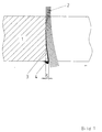
Eine genaue Betrachtung des Schneidablaufs in Bild 1 zeigt in einer Momentaufnahme in einem Werkstück (1) einen normalen runden Schneidstrahl (2), der in das Material eindringt und mit seiner Vorderseite mit erhitztem Stahl reagiert und eine heiße, flüssige Schlackeschicht (3) aus Eisenoxid mit Eisen gemischt erzeugt, die mit der kinetischen Energie des Schneidstrahls (2) nach außen geblasen wird und damit frischer Sauerstoff an die schlackefreien Reaktionsflächenteile kommt. Da die Dicke der Schlackeschicht (3) aber zum Austritt hin zunimmt, die kinetische Energie, ähnlich wie in Bild (2) etwa gleichmäßig verteilt, des Schneidstrahls (2) dagegen etwa gleich bleibt oder durch Reibung abnimmt, kommt es, wie im Geschwindigkeitsprofil des Bildes (2) dargestellt, zu einer Verringerung der Reaktions- bzw. Schneidgeschwindigkeit nach außen (unten) hin. Das wird durch die Bildung eines sich ansetzenden Schneidbarts (4) aus dickflüssiger Schlacke noch verstärkt wird. Damit kommt es zu einem Riefennachlauf (5), der, wenn zu groß, das Schneiden durch unkontrollierte Strahlführung (Durchstecken, Rückwärtsblasen) unmöglich macht.A closer look at the cutting process in Figure 1 shows a snapshot in a workpiece (1) of a normal round cutting jet (2) that penetrates the material and reacts with heated steel on its front side and a hot, liquid slag layer (3) made of iron oxide mixed with iron generated, which is blown out with the kinetic energy of the cutting jet (2) and thus fresh oxygen reaches the slag-free reaction surface parts. However, since the thickness of the slag layer (3) increases towards the outlet, the kinetic energy, similar to that in Figure (2), is approximately evenly distributed, while the cutting beam (2) remains approximately the same or decreases due to friction, as in the speed profile of the Image (2) shown, to a reduction in the reaction or cutting speed to the outside (below). This is reinforced by the formation of a cutting bit (4) made of viscous slag. This leads to a chute wake (5) which, if too large, makes cutting through uncontrolled beam guidance (pushing through, backward blowing) impossible.
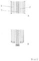
Erfindungsgemäß wird ein Schneidstrahl (2) ähnlich Bild 2 gesucht, der einen Vorderbereich (6) für die erste Reaktion mit normal erzielbarer Strahlgeschwindigkeit hat, und einen Innen- oder Hinterbereich (7) mit hoher Strahlgeschwindigkeit, um die zunehmende Schlackeschicht (3) besser wegzublasen. Noch günstiger wäre ein Trennstrahl (2) mit von vorn nach hinten stark zunehmender Schneidgeschwindigkeit, wenngleich dies schwer zu erzeugen scheint. According to the invention, a cutting jet (2) similar to Figure 2 is sought, which has a front area (6) for the first reaction with a jet speed that can be achieved normally, and an interior or rear area (7) with a high jet speed in order to better blow off the increasing slag layer (3) . A separating jet (2) with a rapidly increasing cutting speed from the front to the rear would be even cheaper, although this appears to be difficult to produce.
Durch die Erzeugung zweier konzentrisch angeordneter Strahlen, einem aufgeblähten Kernstrahl (8) und einem ihm umgebenden verengten Ringstrahl (9), kommt es zu einer Strahlenausbildung, ähnlich dem Geschwindigkeitsprofil Bild 3, insbesondere wenn zwischen einem aufgeblähten Kernstrahl (8) und dem verengtem Ringstrahl (9) von Anfang an keine störende Trennschicht gasförmig oder fest besteht. Dadurch wird nicht nur der verengte Ringstrahl (9) von dem schnelleren, energiereicheren Kernstrahl (8), der sich aufbläht, angetrieben, sondern der aufgeblähte Kernstrahl (8) wird durch seine Umgebung, nämlich dem beschleunigten Ringstrahl (9), weniger gebremst als durch eine andere Art von Umgebung.The generation of two concentrically arranged jets, an inflated core jet (8) and a narrowed ring jet (9) surrounding it, results in a radiation formation similar to the speed profile in Fig. 3 , especially when between an inflated core jet (8) and the narrowed ring jet ( 9) from the beginning there is no disruptive separation layer in gaseous or solid form. As a result, not only is the narrowed ring jet (9) driven by the faster, more energetic core jet (8) that inflates, but the inflated core jet (8) is less slowed down by its surroundings, namely the accelerated ring jet (9) than by a different kind of environment.
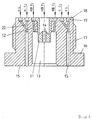
Damit ergibt sich auch die erfindungsgemäße Ausführung der Hochdruck-Injektor-Trenndüse (10) nach Bild 4, die außer der üblichen Heizung mittels den Dosierungsbohrungen (20), den Ringkanälen (19), den Heizbohrungen (15) und den Dichtflächen (18) für die Erzeugung der ringförmig angeordneten Heizflammen und dem Gewinde (17) sowie dem Sechskant (16) zum Einschrauben der Hochdruck-Injektor-Trenndüse (10) in einen Schneidbrenner vor allem eine doppelte Schneidsauerstoffzuführung aufweißt. Einmal fließt ein Hochdruckschneidsauerstoff (HDS O2) in die Kernstrahldüse (11) direkt und zum andern ein Niederdruckschneidsauerstoff (NDS O2) mit Werksnetzdruck in den Ringkanal (19) der Ringstrahlzufuhr (12). Der schnellere Sauerstoffstrahl aus der Kernstrahldüse (11) reißt, sich ausdehnend, den langsameren Sauerstoff aus der Ringstrahlzufuhr (12) im Injektorraum (13) mit, durch die Injektorwirkung entsteht auch ein beschleunigter Vorderbereich des Ringstrahls und ein leicht verzögerter Hinterbereich des Kernstrahls. Durch die Erzeugung des Ringstrahles (9) in der Mündung der Trenndüse (10) wird auch die Geschwindigkeit des aüßeren Bereiches des Ringstrahls (9) wesentlich erhöht.This also results in the inventive design of the high-pressure injector separating nozzle (10) according to Figure 4, which in addition to the usual heating by means of the metering holes (20), the ring channels (19), the heating holes (15) and the sealing surfaces (18) for the production of the ring-shaped heating flames and the thread (17) and the hexagon (16) for screwing the high-pressure injector separating nozzle (10) into a cutting torch, above all, has a double cutting oxygen supply. On the one hand, a high-pressure cutting oxygen (HDS O 2 ) flows directly into the core jet nozzle (11) and, on the other hand, a low-pressure cutting oxygen (NDS O 2 ) with factory network pressure flows into the ring channel (19) of the ring jet supply (12). The faster oxygen jet from the core jet nozzle (11) tears, expanding, the slower oxygen from the ring jet supply (12) in the injector chamber (13), the injector effect also results in an accelerated front area of the ring jet and a slightly delayed rear area of the core jet. By generating the ring jet (9) in the mouth of the separating nozzle (10), the speed of the outer area of the ring jet (9) is also significantly increased.
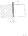
Damit kann nun beim Brennschneiden nach Bild 5 mit einem Trennstrahl (2) gearbeitet werden, der außen erst mit einem schnelleren Ringstrahl (9) reagiert und die Schlacke abschiebt, aber zunehmend nach innen noch schneller mit höher werdender Energie nach außen expandierend die zunehmende Schlackeschicht (3) besser abschiebt bzw. wegbläst und eine bessere Reaktion in den tieferen Bereichen des Werkstücks (1) ermöglicht. Die Schlackeschicht (3) einer Momentaufnahme, Bild 5, wird dünner , der Riefennachlauf (5) wird geringer und der Brennbart (4) kleiner. Insgesamt wird die Schneidgeschwindigkeit höher. With flame cutting according to Fig. 5 , a separating jet (2) can now be used, which only reacts on the outside with a faster ring jet (9) and pushes off the slag, but increasingly increases inwards with increasing energy towards the outside, the increasing slag layer ( 3) better pushes or blows away and enables a better reaction in the deeper areas of the workpiece (1). The slag layer (3) of a snapshot, Figure 5 , becomes thinner, the groove wake (5) becomes smaller and the burdock (4) smaller. Overall, the cutting speed is higher.
Wie auch aus dem Bild 4 erkennbar, wird zur Verbesserung des Kernstrahls (8) eine an sich bekannte plötzliche Verengung der Kernstrahldüse (11) mittels einer nahezu rechtwinkligen Querschnittsverringerung zur Erzeugung einer Stoßfläche vor dem engsten Querschnitt durch eine vorspringende Lippe als Abweiskonus (14) ersetzt, durch den nicht rechtzeitig in den schnellen Kernstrahl (7) eingeordnete Sauerstoffteile, außen mehr zur Umkehr gezwungen, weiter zurückströmen, um sich mit weniger Verwirbelung früher wieder in den Kernstrahl (7) einzufügen. Es kommt so zu einer günstigeren Einschnürungswirkung.As can also be seen in Figure 4 , a sudden narrowing of the core jet nozzle (11), which is known per se, is replaced by an almost rectangular reduction in cross-section in order to improve the core jet (8) by means of a protruding lip in front of the narrowest cross section by a projecting lip as a deflection cone (14) , due to the oxygen parts not being arranged in time in the fast core jet (7), forced more to reverse on the outside, in order to fit back into the core jet (7) earlier with less turbulence. This leads to a more favorable constriction effect.
Während mit bekannten Hochleistungsdüsen und üblichen, ziemlich hohen Arbeitsdrücken von 10 - 12 bar an kaltem Stahl von 250 mm Dicke Schneidgeschwindigkeiten von 220 mm/min möglich waren, konnten mit den Hochdruck-Injektor-Trenndüsen (10), versorgt mit Sauerstoff innen von 32 bar und außen 10 bar, eine Schneidgeschwindigkeit von 310 mm/min erzielt werden. Die Zunahme des gesamten Sauerstoffverbrauchs bei diesen Versuchen lag etwa nur bei 30 %. Unberücksichtigt blieben die Energiekosten zur Druckerhöhung von 10 auf 32 bar für ca. 20 Nm3/h, wie auch die Amortisation der aufwendigen Düsen, Brenner und Versorgung. While cutting speeds of 220 mm / min were possible with known high-performance nozzles and usual, rather high working pressures of 10 - 12 bar on cold steel with a thickness of 250 mm, the high-pressure injector separating nozzles (10), supplied with oxygen inside of 32 bar and outside 10 bar, a cutting speed of 310 mm / min can be achieved. The increase in total oxygen consumption in these experiments was only about 30%. The energy costs for increasing the pressure from 10 to 32 bar for approx. 20 Nm 3 / h, as well as the amortization of the complex nozzles, burners and supply were not taken into account.
DE 25 21 253 A1 Linde AG DE 25 21 253 A1 Linde AG
- 11
- Werkstückworkpiece
- 22nd
- SchneidstrahlCutting beam
- 33rd
- SchlackeschichtSlag layer
- 44th
- SchlackebartSlag beard
- 55
- RiefennachlaufGrooving
- 66
- Vorderbereich (Ringstrahl)Front area (ring beam)
- 77
- Innen- oder Hinterbereich (Kernstrahl)Indoor or rear area (core jet)
- 88th
- aufgeblähter Kernstrahlinflated core jet
- 99
- verengter Ringstrahlnarrowed ring beam
- 1010th
- Hochdruck-Injektor-TrenndüseHigh pressure injector separating nozzle
- 1111
- KernstrahldüseCore jet nozzle
- 1212th
- RingstrahlzufuhrRing beam feed
- 1313
- InjektorraumInjector room
- 1414
- AbweiskonusDeflection cone
- 1515
- HeizbohrungenHeating holes
- 1616
- SechskantHexagon
- 1717th
- Gewindethread
- 1818th
- DichtflächeSealing surface
- 1919th
- RingkanalRing channel
- 2020th
- DosierungsbohrungDosing hole
- HGHG
- HeizgasHeating gas
- H O2 HO 2
- HeizsauerstoffHeating oxygen
- NDS O2 NDS O 2
- NiederdruckschneidsauerstoffLow pressure cutting oxygen
- HDS O2 HDS O 2
- HochdruckschneidsauerstoffHigh pressure cutting oxygen
Claims (1)
- Method, apparatus and arrangement for fast cutting of steel using oxygen in continuous steel casting plants, cutting being performed with a concentric double-separating jet of oxygen, whose core consists of high-pressure and/or high-speed oxygen and whose ring consists of low-pressure and/or low-speed oxygen, forming together a jet unit with different pressure and/or speed profiles defined by that a high-pressure-injector-separating nozzle (10) is used for producing the concentric double-separating jet of oxygen. The nozzle (10) is equipped with an oxygen nozzle bore with rejecting cone (14) for the high-pressure/high speed jet part and a surrounding ring passage for the low-pressure/low-speed jet, which merge into a joint outlet bore and therefore enable slower jet parts to be carried along by quicker ones and a reduction of friction in the nozzle.
Priority Applications (2)
| Application Number | Priority Date | Filing Date | Title |
|---|---|---|---|
| EP19950102728 EP0728554B1 (en) | 1995-02-25 | 1995-02-25 | Apparatus for quickly cutting of steel using oxygen in continuous steel casting plants |
| DE59508862T DE59508862D1 (en) | 1995-02-25 | 1995-02-25 | Device for the fastest separation of steel with oxygen in continuous steel casting plants |
Applications Claiming Priority (1)
| Application Number | Priority Date | Filing Date | Title |
|---|---|---|---|
| EP19950102728 EP0728554B1 (en) | 1995-02-25 | 1995-02-25 | Apparatus for quickly cutting of steel using oxygen in continuous steel casting plants |
Publications (2)
| Publication Number | Publication Date |
|---|---|
| EP0728554A1 EP0728554A1 (en) | 1996-08-28 |
| EP0728554B1 true EP0728554B1 (en) | 2000-11-15 |
Family
ID=8219015
Family Applications (1)
| Application Number | Title | Priority Date | Filing Date |
|---|---|---|---|
| EP19950102728 Expired - Lifetime EP0728554B1 (en) | 1995-02-25 | 1995-02-25 | Apparatus for quickly cutting of steel using oxygen in continuous steel casting plants |
Country Status (2)
| Country | Link |
|---|---|
| EP (1) | EP0728554B1 (en) |
| DE (1) | DE59508862D1 (en) |
Cited By (1)
| Publication number | Priority date | Publication date | Assignee | Title |
|---|---|---|---|---|
| CN102229016A (en) * | 2011-06-25 | 2011-11-02 | 章丘市裕丰气割队 | flame cleaning gun cutting nozzle |
Family Cites Families (7)
| Publication number | Priority date | Publication date | Assignee | Title |
|---|---|---|---|---|
| US3389861A (en) * | 1965-10-26 | 1968-06-25 | Tanaka Seisakusho Kk | Device for gas cutting utilizing a shield gas |
| DE1927523A1 (en) * | 1969-05-30 | 1970-12-03 | Zentralinstitut Schweiss | Protective gas shielding for torch-cutting - of thick materials |
| DE2215538A1 (en) * | 1971-05-12 | 1972-11-16 | Zentralinstitut für Schweißtechnik der DDR, χ 4030 Halle | Oxygas cutting system - with super sonically accelerated oxygen and surrounding compressed air jet |
| DE2521253A1 (en) * | 1975-05-13 | 1976-11-25 | Linde Ag | TURNING NOZZLE |
| DE2633719C2 (en) * | 1976-07-27 | 1986-06-26 | Linde Ag, 6200 Wiesbaden | Method for operating a cutting torch and nozzle for carrying out the method |
| FR2658748B1 (en) * | 1990-02-23 | 1994-12-23 | Soudure Autogene Francaise | LIQUID JET CUTTING METHOD AND DEVICE. |
| FR2692185B1 (en) * | 1992-06-12 | 1996-03-08 | Creusot Loire | METHOD FOR MANUFACTURING A METAL PART BY OXYCOUPING, OXYCOUPING DEVICE AND METAL PIECE OBTAINED THEREBY. |
-
1995
- 1995-02-25 EP EP19950102728 patent/EP0728554B1/en not_active Expired - Lifetime
- 1995-02-25 DE DE59508862T patent/DE59508862D1/en not_active Expired - Fee Related
Cited By (1)
| Publication number | Priority date | Publication date | Assignee | Title |
|---|---|---|---|---|
| CN102229016A (en) * | 2011-06-25 | 2011-11-02 | 章丘市裕丰气割队 | flame cleaning gun cutting nozzle |
Also Published As
| Publication number | Publication date |
|---|---|
| EP0728554A1 (en) | 1996-08-28 |
| DE59508862D1 (en) | 2000-12-21 |
Similar Documents
| Publication | Publication Date | Title |
|---|---|---|
| DE4332345C2 (en) | Process and fleece blowing system for the production of a spunbonded web with high filament speed | |
| DE102016215019B4 (en) | Process for laser cutting with optimized gas dynamics | |
| DE102008048496A1 (en) | Sheet metal molded part manufacturing method, involves forming flat body into component using processing technologies, discharging component from processing zone, and cooling component at room temperature | |
| DE10352546A1 (en) | Method and device for applying an adjustable tensile stress distribution, in particular in the edge regions of cold-rolled metal strips | |
| DE4225011B4 (en) | Device for producing a metal-plastic composite pipe | |
| DE2555899C2 (en) | Process for producing hollow fibres from inorganic meltable materials and device for carrying out the process | |
| EP0265757B1 (en) | Method and arrangement for rolling continuously cast profiles | |
| EP3233397A1 (en) | Liquid jet cutting method | |
| DE4292014C2 (en) | Method of making a long high pressure fuel line | |
| EP0728554B1 (en) | Apparatus for quickly cutting of steel using oxygen in continuous steel casting plants | |
| DE2536611A1 (en) | Tool with tapping shank for perforating plate - has mandrel piercing hole by heat and axial pressure | |
| DE4328160A1 (en) | Helical screw for plastic extruder - having special corrosion and wear resistant tips to screw threads | |
| EP3088087A1 (en) | Spray nozzle and method for producing non-round spray cones | |
| EP0780184A1 (en) | Device for longitudinal and transversely dividing cold or hot steel slaps | |
| DE10329696B3 (en) | Method for producing a plurality of curved extruded profiles | |
| DE10329697B3 (en) | Method for producing curved workpieces by extrusion and rounding | |
| DE2512854B2 (en) | Process for the production of twist drills or other tools | |
| DE708104C (en) | Extrusion press for the production of pipes | |
| EP1558438B1 (en) | Device for cooling and calibrating plastic profiled pieces | |
| EP3057721A1 (en) | Extrusion press for producing flat sheets | |
| EP0968778A1 (en) | Device and method for continuous casting of hollow profiles | |
| EP1060059B1 (en) | Method for cutting steel bodies with a water jet | |
| DE19732444C1 (en) | Prevention of back end losses of hot rolled pipes produced on Assel roll stands | |
| EP1455966A1 (en) | Hydroforming method | |
| DE2128436C (en) | Granulating nozzle |
Legal Events
| Date | Code | Title | Description |
|---|---|---|---|
| PUAI | Public reference made under article 153(3) epc to a published international application that has entered the european phase |
Free format text: ORIGINAL CODE: 0009012 |
|
| AK | Designated contracting states |
Kind code of ref document: A1 Designated state(s): DE FR GB IT |
|
| AX | Request for extension of the european patent |
Free format text: SI |
|
| RAX | Requested extension states of the european patent have changed |
Free format text: SI |
|
| ITCL | It: translation for ep claims filed |
Representative=s name: MEDITER TEC |
|
| GBC | Gb: translation of claims filed (gb section 78(7)/1977) | ||
| EL | Fr: translation of claims filed | ||
| RBV | Designated contracting states (corrected) |
Designated state(s): DE FR GB IT |
|
| 17P | Request for examination filed |
Effective date: 19970108 |
|
| 17Q | First examination report despatched |
Effective date: 19981021 |
|
| GRAG | Despatch of communication of intention to grant |
Free format text: ORIGINAL CODE: EPIDOS AGRA |
|
| RTI1 | Title (correction) |
Free format text: APPARATUS FOR QUICKLY CUTTING OF STEEL USING OXYGEN IN CONTINUOUS STEEL CASTING PLANTS |
|
| RTI1 | Title (correction) |
Free format text: APPARATUS FOR QUICKLY CUTTING OF STEEL USING OXYGEN IN CONTINUOUS STEEL CASTING PLANTS |
|
| RTI1 | Title (correction) |
Free format text: APPARATUS FOR QUICKLY CUTTING OF STEEL USING OXYGEN IN CONTINUOUS STEEL CASTING PLANTS |
|
| GRAG | Despatch of communication of intention to grant |
Free format text: ORIGINAL CODE: EPIDOS AGRA |
|
| GRAH | Despatch of communication of intention to grant a patent |
Free format text: ORIGINAL CODE: EPIDOS IGRA |
|
| GRAH | Despatch of communication of intention to grant a patent |
Free format text: ORIGINAL CODE: EPIDOS IGRA |
|
| GRAA | (expected) grant |
Free format text: ORIGINAL CODE: 0009210 |
|
| AK | Designated contracting states |
Kind code of ref document: B1 Designated state(s): DE FR GB IT |
|
| REF | Corresponds to: |
Ref document number: 59508862 Country of ref document: DE Date of ref document: 20001221 |
|
| ET | Fr: translation filed | ||
| GBT | Gb: translation of ep patent filed (gb section 77(6)(a)/1977) |
Effective date: 20010110 |
|
| PLBE | No opposition filed within time limit |
Free format text: ORIGINAL CODE: 0009261 |
|
| STAA | Information on the status of an ep patent application or granted ep patent |
Free format text: STATUS: NO OPPOSITION FILED WITHIN TIME LIMIT |
|
| 26N | No opposition filed | ||
| REG | Reference to a national code |
Ref country code: GB Ref legal event code: IF02 |
|
| PGFP | Annual fee paid to national office [announced via postgrant information from national office to epo] |
Ref country code: FR Payment date: 20020204 Year of fee payment: 8 |
|
| PGFP | Annual fee paid to national office [announced via postgrant information from national office to epo] |
Ref country code: GB Payment date: 20020208 Year of fee payment: 8 |
|
| PGFP | Annual fee paid to national office [announced via postgrant information from national office to epo] |
Ref country code: DE Payment date: 20020528 Year of fee payment: 8 |
|
| PG25 | Lapsed in a contracting state [announced via postgrant information from national office to epo] |
Ref country code: GB Free format text: LAPSE BECAUSE OF NON-PAYMENT OF DUE FEES Effective date: 20030225 |
|
| PG25 | Lapsed in a contracting state [announced via postgrant information from national office to epo] |
Ref country code: DE Free format text: LAPSE BECAUSE OF NON-PAYMENT OF DUE FEES Effective date: 20030902 |
|
| GBPC | Gb: european patent ceased through non-payment of renewal fee | ||
| PG25 | Lapsed in a contracting state [announced via postgrant information from national office to epo] |
Ref country code: FR Free format text: LAPSE BECAUSE OF NON-PAYMENT OF DUE FEES Effective date: 20031031 |
|
| REG | Reference to a national code |
Ref country code: FR Ref legal event code: ST |
|
| PG25 | Lapsed in a contracting state [announced via postgrant information from national office to epo] |
Ref country code: IT Free format text: LAPSE BECAUSE OF NON-PAYMENT OF DUE FEES Effective date: 20050225 |