EP0728533A1 - Verfahren und Wandler zum Aussenden von akustischen Wellen in einer Flüssigkeit mit einer betonten Richtcharakteristik bei Niederfrequenzen - Google Patents
Verfahren und Wandler zum Aussenden von akustischen Wellen in einer Flüssigkeit mit einer betonten Richtcharakteristik bei Niederfrequenzen Download PDFInfo
- Publication number
- EP0728533A1 EP0728533A1 EP96400362A EP96400362A EP0728533A1 EP 0728533 A1 EP0728533 A1 EP 0728533A1 EP 96400362 A EP96400362 A EP 96400362A EP 96400362 A EP96400362 A EP 96400362A EP 0728533 A1 EP0728533 A1 EP 0728533A1
- Authority
- EP
- European Patent Office
- Prior art keywords
- transducer
- housing
- rigid
- axis
- cavities
- Prior art date
- Legal status (The legal status is an assumption and is not a legal conclusion. Google has not performed a legal analysis and makes no representation as to the accuracy of the status listed.)
- Granted
Links
Images


Classifications
-
- B—PERFORMING OPERATIONS; TRANSPORTING
- B06—GENERATING OR TRANSMITTING MECHANICAL VIBRATIONS IN GENERAL
- B06B—METHODS OR APPARATUS FOR GENERATING OR TRANSMITTING MECHANICAL VIBRATIONS OF INFRASONIC, SONIC, OR ULTRASONIC FREQUENCY, e.g. FOR PERFORMING MECHANICAL WORK IN GENERAL
- B06B1/00—Methods or apparatus for generating mechanical vibrations of infrasonic, sonic, or ultrasonic frequency
- B06B1/02—Methods or apparatus for generating mechanical vibrations of infrasonic, sonic, or ultrasonic frequency making use of electrical energy
- B06B1/06—Methods or apparatus for generating mechanical vibrations of infrasonic, sonic, or ultrasonic frequency making use of electrical energy operating with piezoelectric effect or with electrostriction
- B06B1/0607—Methods or apparatus for generating mechanical vibrations of infrasonic, sonic, or ultrasonic frequency making use of electrical energy operating with piezoelectric effect or with electrostriction using multiple elements
- B06B1/0611—Methods or apparatus for generating mechanical vibrations of infrasonic, sonic, or ultrasonic frequency making use of electrical energy operating with piezoelectric effect or with electrostriction using multiple elements in a pile
- B06B1/0618—Methods or apparatus for generating mechanical vibrations of infrasonic, sonic, or ultrasonic frequency making use of electrical energy operating with piezoelectric effect or with electrostriction using multiple elements in a pile of piezo- and non-piezoelectric elements, e.g. 'Tonpilz'
Definitions
- the subject of the present invention is a method and transducers for emitting acoustic waves in a liquid with marked directivity at low frequencies.
- the technical sector of the invention is the field of manufacturing electroacoustic transducers for the emission of acoustic waves when immersed in a liquid.
- the main applications of the invention are all those which essentially require directivity, that is to say those which need acoustic emission only in at most one given master plane, a plane in which this emission will be all the more powerful as this directivity of the transducer is high and this emission propagates and then concentrates precisely in a volume of the lowest possible height around the emission master plan instead of being diffused almost uniformly in all the directions along 360 steradians.
- one of these main applications is the possibility of emitting and / or receiving acoustic waves with also then an electroacoustic efficiency or rather a response per watt, as defined below, high, in horizontal planes to study the different properties, by layers or slices, of the oceans, such as temperature, salinity, density, currents, etc., both for understanding the phenomena and their fluctuation over time.
- a technique known as "acoustic ocean tomography” has been developed for this to generate a three-dimensional image of the area crossed by sound waves, as is done in medicine with "X” beams, or in geology of the earth's crust with seismic waves: in the oceanic domain, low frequency acoustic waves are used.
- These subject to known physical laws decrease in intensity as the distance from their emission source, can be accelerated, or deflected, or slowed when they meet and move with the currents, be attenuated , reflected or refracted by variations in temperature, density, or salinity ... Their behavior being predictable and interpretable with precision by physical laws, the disturbances of the acoustic field then provide the information necessary for the determination of certain properties of oceanic masses.
- low frequency acoustic waves are used, and even at the lowest possible frequencies, because their energy is less attenuated with distance than for higher frequencies: thus waves of frequencies below 100 hertz travel thousands of kilometers without loss significant energy.
- the waves emitted either above or below this depth of the minimum speed channel, or upwards, or downwards, move close to the surface or close to the ocean floor, and following a trajectory crossing regions of high speed; thus they reach receivers first in most regions of the ocean, because their speed is higher on average, and a very clear unique sound is received at a distant point in the form of several reproductions of the original sound.
- assemblies composed of at least one low frequency acoustic transceiver coupled and fixed to a battery container ensuring its autonomy: these assemblies are retained at their lower part by an anchoring cable connected to the bottom with a release mechanism to ensure its recovery, and at their upper part to a cable pulled upwards by a set of floating buoys, and carrying hydrophones; their position in geographic coordinates is determined by any system, either surface or background.
- a tomographic beacon is described in the publication cited above by Messrs. SPINDEL and WORCESTER, with transducers of various known types, some of which have made it possible to carry out tests and research during oceanographic cruises, during the last five to six years.
- transducer of external cylindrical shape, hollow and open at its center and radiating the acoustic waves radially in all directions, along a plane perpendicular to its axis, thanks in particular to a crown arrangement of at least at least six cylindrical electroacoustic motors each maintained between two countermasses, themselves common to two adjacent motors and carrying pavilions arranged parallel to the axis to cover the cylindrical external periphery of the transducer.
- the problem posed is therefore to produce a low frequency transducer having essentially a good directivity of emission in elevation with respect to a reference plane while being omnidirectional in bearing in this plane and moreover having a response per watt noted S w , c 'is to say a sound level ratio in the direction or the desired emission plan of reference on the applied electric power, high, especially in low frequencies from 100 to 500 Hz.
- the solution to the problem posed is a method for emitting acoustic waves in a liquid from a submersible electroacoustic transducer comprising a rigid cylindrical hollow housing of axis XX 'and open at its two axial ends and at the interior of which are arranged coaxially with the latter two identical electroacoustic motors placed on either side of a central countermass and the opposite ends of which are each surrounded by a flag conforming to the interior shape of said rigid housing.
- these transducers are used in particular to emit low frequency acoustic waves in water in a determined direction; for an application of this type of mono or double "Tonpilz" transducer to high power emissions, mention may be made of the application FR. 2,663,182 by Gilles GROSSO published on December 13, 1991, which describes additional devices to obtain increased power.
- the objective of the present invention is therefore very different since, essentially, we want to be able to transmit omnidirectionally in a given directional plane and not in a single given direction and to increase the response per watt of such transducers, even and above all at low frequencies.
- the said rigid housing is extended in the axis XX 'beyond the two pavilions and two cavities are thus formed, the resonance of which is determined for correspond to the desired transmission frequency and the internal wall of said rigid housing is arranged as close as possible to the edges of the external perimeter of said pavilions.
- these can enclose, either only water, or closed elastic tubes, sealed and filled with gas, or at least one flexible bladder occupying a part of its volume and filled with a more compressible fluid than the immersion liquid: the advantage of the presence of such so-called compliant tubes and / or a bladder is also to reduce the loss of yield and attenuation of frequencies between the two resonance peaks specific to the transducer, one of which is linked to the mechanical resonance of the whole transducer, and the other to that of its cavity.
- test transducers made according to the present invention have made it possible to reduce the necessary power consumed for a given emission by 35 to 65% of that of a current omnidirectional transducer.
- the present invention can also be used in the context of realizations of directional sonars and in any application in which a high response per watt is desired, insofar as the storage of the energy to be supplied is limited.
- Figure 1 is a longitudinal sectional view of a transducer according to the invention.
- FIG. 2 represents the sound levels emitted on site and in bearing of a transducer according to the invention.
- Figure 3 is a view of the directivity of the field transducer.
- Figure 4 is a view of the directivity in site of a transducer according to the invention.
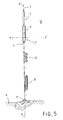
- Figure 5 is an overview of a wetting line for tomographic use of a transducer according to the invention.
- the submersible electroacoustic transducer 1 as shown in section in FIG. 1, comprises in a known manner two electroacoustic motors 13, aligned along the axis XX ', placed on either side of a central counterweight 14 and coaxially with the interior of a rigid cylindrical casing 2, covering all of said motors 1 up to the end pavilions 15 thereof and open itself at its two ends; the cavity 6 thus delimited by the rear of said pavilions and the housing itself is in communication with the external immersion liquid 10, by the only annular spaces 24 between the internal shape of said rigid housing 2 and the peripheral edges of the ends of the pavilions 15: this space 24 should be as small as possible, ie less than 0.5 mm to avoid pumping of the liquid between the front and the rear of said pavilions. No other communication or vent is made in the housing outside the holes necessary for the passage of the hull and the fixings but then closed and sealed to avoid any acoustic loss.
- said rigid housing 2 extends along its axis XX 'beyond the two flags 15 and constitutes therewith two cavities 16 whose resonance corresponds to the desired transmission frequency.
- said cavities 16 can contain water, either alone or with elastic tubes 18 closed, sealed and filled with gas, which are called compliant tubes, such as those described in patent application FR. 2,665,998 of May 5, 1988.
- the opening 17 of said cavities 16 on the outside are of a diameter d smaller than the internal diameter D of the rigid housing 2: a compromise dimensional must then be found between the total dimension of the cavity, the compliant tubes or other devices as described below, and the diameter of this opening.
- said cavity 6 inside said box 2 and located between the two pavilions 15 and in which said electroacoustic motors 1 are located encloses elastic tubes 18, closed, sealed and filled with gas, therefore called compliants.
- Said electroacoustic motors 1 can be of the piezoelectric type, but also magnetostrictive cylinders surrounded by an excitation coil. Such dual motor electroacoustic transducers are also called double Tonpilz.
- said electroacoustic motors 13 and the intermediate counterweight 14 are shown assembled assembled, by means of different connecting pieces 19 connecting said electroacoustic motors to the housing 2, by any means of attachment, and allowing freedom of movement of the pavilions 15 with respect to said housing, but determining an almost closed internal cavity 6 between the respective edges 13 of said pavilions and of said housing, as indicated above.
- the power supply of said electroacoustic motors 19 is supplied by any power cable 20, fixed to said connecting pieces 19 by an electrical connector; all of the elements are sealed despite the total immersion of the various elements which constitute it so as to be able to immerse it at any depth, limited simply by the resistance of the compliant tubes 18 when they are present.
- said compliant tubes 18 can be replaced in any one of the cavities 6, 16 by at least one flexible bladder occupying at least part if not all of the entire volume of the cavity concerned and filled with a more compressible fluid than the ambient liquid 10: this can be applied either for the cavity 6, or for the end cavities 16, or for all of said cavities.
- the fluid occupying the volumes delimited by the skin of said bladders must fill at best and preferably practically the entire cavity, because its volume must in fact be greater than that of the compliant tubes 18 represented and as described above, so as to have compressibility characteristics equivalent to that of said tubes as used to date in other types of transducers.
- the compressibility of said fluid must in fact be less than 10 9 N / m 2 , defined by the product of its density P f with the square of the speed of propagation of sound in this fluid C f .
- a fluid whose viscosity is not too high, ie lower than that of water preferably 6.5 x 10 -7 m 2 / second, which is that of silicone oil; and even with a product from the family of fully fluorinated organic compounds such as C8H18, the kinematic viscosity is 4 x 10⁻⁷ m2 / second: this product also has the characteristic of being stable, even at fairly low temperatures, and at ambient temperatures.
- the total length L of the rigid housing 2 is about half to within 20%, or between 0.8 and 1.2 of the half the wavelength of the acoustic waves emitted by said transducer 1.
- FIG. 3 gives the plot of the sound level in decibels according to the emission plane in bearing YY 'of FIG. 1 and Figure 5 also.
- FIG. 4 represents the plot of the sound level in decibels in site directivity along a vertical plane passing through the axis XX 'of the transducer whose length is just equal to that of the half-wavelength of the frequency emitted to have emission lobes along the axis XX 'practically canceled and therefore concentrating all the emission power emitted along lobes surrounding the plane YY'.
- FIG. 5 represents one of the main applications of the invention in the field of tomography, in which an assembly makes it possible to maintain vertically, in an oceanic environment submerged 10, a container 5 for storing energy and an electronic and electrical system necessary for the operation of the acoustic transmitter 1, integral with said container: the transducer 1 is connected to this container by any attachment system from lugs of attachment 21 as shown in FIG. 1 laterally and peripherally in the central part of the rigid housing 2 and connected directly to the acoustic motors 1 so as to allow the assembly of said housing to resonate and not disturbed by the pulls of the attachment system.
- a mooring line comprises, on the one hand downwards a cable 4 connected to an anchoring system 11 placed at the bottom 9 of the ocean 10 and, on the other hand, a traction cable 3 upwards, and connected to any floating device not shown in the figure; it can be submerged or very close to the surface to be spotted, and its buoyancy must be greater than that of all the elements which must remain at a given depth such as all those represented in this figure above the bottom 9, and less than the force of the anchoring system 11 reduced by the hydrodynamic forces applied to the assembly.
- Said lower mooring line 4 may include a release device 8 which can make it possible to recover all of the wetting, including the autonomous acoustic source 1 with its container 5, except of course the anchoring device 11, and this at the end of operations or in the event of technical problems on the equipment: any known system of this type can be used, and its implementation method is known elsewhere, without it being necessary to describe it more precisely in the present description.
- this lower mooring line 4 may include various buoyancy devices and / or mooring stabilizer 12, in order on the one hand not to pull too much on the attachment systems between the containers and the transducer and, on the other hand, to stabilize the mooring line in an almost stable direction, so as to avoid gyration effects which could be detrimental to the mechanical systems and to the measurements.
- a set of hydrophone networks 7 or listening flutes makes it possible to collect acoustic waves which can be emitted by others beacon devices of the same type. If other transmitters 1 are arranged at different depths, the mooring line, 4 or 3, of this beacon may then have hydrophone networks 7 arranged at these same depths, as indicated above.
- the assembly of the holding device constituted by the various elements of the mooring line 3, 4, therefore defines a determined axis XX ′ vertical, and is fixed on the storage container 5 and on the transducer 1 at their two extreme ends. , without subjecting the rigid housing 2 of the transducer proper to any effort.
- an upper protective crown and a lower protective crown can be arranged which enclose the attachment devices to the parts of the mooring lines 3 and 4.
Landscapes
- Engineering & Computer Science (AREA)
- Mechanical Engineering (AREA)
- Transducers For Ultrasonic Waves (AREA)
- Measurement Of Velocity Or Position Using Acoustic Or Ultrasonic Waves (AREA)
Applications Claiming Priority (2)
| Application Number | Priority Date | Filing Date | Title |
|---|---|---|---|
| FR9502094 | 1995-02-23 | ||
| FR9502094A FR2731130B1 (fr) | 1995-02-23 | 1995-02-23 | Procede et transducteurs pour emettre des ondes acoustiques dans un liquide avec une directivite marquee aux basses frequences |
Publications (2)
| Publication Number | Publication Date |
|---|---|
| EP0728533A1 true EP0728533A1 (de) | 1996-08-28 |
| EP0728533B1 EP0728533B1 (de) | 1998-08-26 |
Family
ID=9476435
Family Applications (1)
| Application Number | Title | Priority Date | Filing Date |
|---|---|---|---|
| EP19960400362 Expired - Lifetime EP0728533B1 (de) | 1995-02-23 | 1996-02-22 | Verfahren und Wandler zum Aussenden von akustischen Wellen in einer Flüssigkeit mit einer betonten Richtcharakteristik bei Niederfrequenzen |
Country Status (4)
| Country | Link |
|---|---|
| EP (1) | EP0728533B1 (de) |
| CA (1) | CA2170089A1 (de) |
| DE (1) | DE69600548T2 (de) |
| FR (1) | FR2731130B1 (de) |
Cited By (1)
| Publication number | Priority date | Publication date | Assignee | Title |
|---|---|---|---|---|
| US7104357B2 (en) * | 2000-12-21 | 2006-09-12 | Institut Francais Du Petrole | Device for generating focused elastic waves in a material medium such as underground, and method using same |
Citations (5)
| Publication number | Priority date | Publication date | Assignee | Title |
|---|---|---|---|---|
| US2390847A (en) * | 1941-08-13 | 1945-12-11 | Rca Corp | Signal translating apparatus |
| FR2600227A1 (fr) * | 1986-06-14 | 1987-12-18 | Honeywell Elac Nautik Gmbh | Transducteur electroacoustique tubulaire |
| EP0462037A1 (de) * | 1990-06-12 | 1991-12-18 | Gilles A . Grosso | Elektroakustischer Unterwasserwandler |
| FR2665998A1 (fr) * | 1988-05-05 | 1992-02-21 | France Etat Armement | Procedes et transducteurs electro-acoustiques pour emettre des ondes acoustiques a basse frequence dans un liquide. |
| EP0506529A1 (de) * | 1991-03-29 | 1992-09-30 | Thomson-Csf | Richtantenne für akustische Niederfrequenzwellen |
-
1995
- 1995-02-23 FR FR9502094A patent/FR2731130B1/fr not_active Expired - Fee Related
-
1996
- 1996-02-22 DE DE1996600548 patent/DE69600548T2/de not_active Expired - Fee Related
- 1996-02-22 EP EP19960400362 patent/EP0728533B1/de not_active Expired - Lifetime
- 1996-02-22 CA CA 2170089 patent/CA2170089A1/fr not_active Abandoned
Patent Citations (5)
| Publication number | Priority date | Publication date | Assignee | Title |
|---|---|---|---|---|
| US2390847A (en) * | 1941-08-13 | 1945-12-11 | Rca Corp | Signal translating apparatus |
| FR2600227A1 (fr) * | 1986-06-14 | 1987-12-18 | Honeywell Elac Nautik Gmbh | Transducteur electroacoustique tubulaire |
| FR2665998A1 (fr) * | 1988-05-05 | 1992-02-21 | France Etat Armement | Procedes et transducteurs electro-acoustiques pour emettre des ondes acoustiques a basse frequence dans un liquide. |
| EP0462037A1 (de) * | 1990-06-12 | 1991-12-18 | Gilles A . Grosso | Elektroakustischer Unterwasserwandler |
| EP0506529A1 (de) * | 1991-03-29 | 1992-09-30 | Thomson-Csf | Richtantenne für akustische Niederfrequenzwellen |
Cited By (1)
| Publication number | Priority date | Publication date | Assignee | Title |
|---|---|---|---|---|
| US7104357B2 (en) * | 2000-12-21 | 2006-09-12 | Institut Francais Du Petrole | Device for generating focused elastic waves in a material medium such as underground, and method using same |
Also Published As
| Publication number | Publication date |
|---|---|
| DE69600548T2 (de) | 1999-02-11 |
| CA2170089A1 (fr) | 1996-08-24 |
| DE69600548D1 (de) | 1998-10-01 |
| FR2731130B1 (fr) | 1997-04-11 |
| FR2731130A1 (fr) | 1996-08-30 |
| EP0728533B1 (de) | 1998-08-26 |
Similar Documents
| Publication | Publication Date | Title |
|---|---|---|
| EP3084755B1 (de) | Kompakte omnidirektionale antenne für ein eintauch-sonar | |
| FR2961902A1 (fr) | Vibrateur acoustique marin ayant une amplitude a basse frequence accrue | |
| EP0684084B1 (de) | Verfahren und Wandler zum Ausstrahlen von Breitband- und Niederfrequenz-Schallwellen in unbegrenzter Tauchtiefe | |
| EP3198586B1 (de) | Rundstrahlantenne | |
| EP2858760A2 (de) | Vorrichtung und verfahren zum fokussieren von impulsen | |
| FR2971112A1 (fr) | Transducteur electro-acoustique basse frequence et procede de generation d'ondes acoustiques. | |
| CA2208982A1 (fr) | Procede d'emission acoustique pour sonar | |
| FR2889744A1 (fr) | Hydrophone flexible. | |
| EP0323305B1 (de) | Rohrförmiger piezo-elektrischer Sensor mit grosser Empfindlichkeit | |
| EP0728535B1 (de) | Verfahren und Vorrichtung zur Verminderung der Resonanzfrequenz von Hohlräumen von Unterwasserwandlern | |
| EP0728533B1 (de) | Verfahren und Wandler zum Aussenden von akustischen Wellen in einer Flüssigkeit mit einer betonten Richtcharakteristik bei Niederfrequenzen | |
| EP3677051B1 (de) | Wasserschallgehäuse | |
| FR2609337A1 (fr) | Transducteur electroacoustique a decharges electriques disruptives pour analyse de sondages | |
| FR2936876A1 (fr) | Antennes laterales d'emission acoustique pour prospection sismique sous-marine | |
| WO1999064897A1 (fr) | Dispositif d'acquisition sismique a haute resolution | |
| FR2728425A1 (fr) | Antenne lineaire electroacoustique d'emission et antenne d'emission/reception comprenant une telle antenne | |
| CA2137187C (fr) | Procede d'emission d'ondes acoustiques tres basses frequences a forte puissance, et transducteurs correspondants | |
| EP0881001B1 (de) | Elektrodynamischer Wandler für Unterwasser-Akustik | |
| WO2002050572A1 (fr) | Dispositif pour engendrer des ondes elastiques focalisees dans un milieu materiel tel que le sous-sol, et methode pour sa mise en oeuvre | |
| FR2725867A1 (fr) | Source autonome acoustique pour la tomographie des oceans | |
| CA2109466C (fr) | Procede et transducteurs pour emettre des ondes acoustiques basse frequence dans un liquide en immersion illimitee | |
| WO2001035123A1 (fr) | Antenne lineaire acoustique remorquee a faible bruit | |
| EP0897176B1 (de) | Unterwasserschallabsorber | |
| FR3079620A1 (fr) | Vibrateur marin sismique | |
| EP1116023B1 (de) | Verfahren und vorrichtung zum erzeugen von vertikalen messprofilen von meerwassercharakteristischen grössen |
Legal Events
| Date | Code | Title | Description |
|---|---|---|---|
| PUAI | Public reference made under article 153(3) epc to a published international application that has entered the european phase |
Free format text: ORIGINAL CODE: 0009012 |
|
| 17P | Request for examination filed |
Effective date: 19960312 |
|
| AK | Designated contracting states |
Kind code of ref document: A1 Designated state(s): DE GB IT SE |
|
| GRAG | Despatch of communication of intention to grant |
Free format text: ORIGINAL CODE: EPIDOS AGRA |
|
| 17Q | First examination report despatched |
Effective date: 19970616 |
|
| GRAG | Despatch of communication of intention to grant |
Free format text: ORIGINAL CODE: EPIDOS AGRA |
|
| GRAH | Despatch of communication of intention to grant a patent |
Free format text: ORIGINAL CODE: EPIDOS IGRA |
|
| GRAH | Despatch of communication of intention to grant a patent |
Free format text: ORIGINAL CODE: EPIDOS IGRA |
|
| GRAA | (expected) grant |
Free format text: ORIGINAL CODE: 0009210 |
|
| AK | Designated contracting states |
Kind code of ref document: B1 Designated state(s): DE GB IT SE |
|
| REF | Corresponds to: |
Ref document number: 69600548 Country of ref document: DE Date of ref document: 19981001 |
|
| GBT | Gb: translation of ep patent filed (gb section 77(6)(a)/1977) |
Effective date: 19980914 |
|
| PLBE | No opposition filed within time limit |
Free format text: ORIGINAL CODE: 0009261 |
|
| STAA | Information on the status of an ep patent application or granted ep patent |
Free format text: STATUS: NO OPPOSITION FILED WITHIN TIME LIMIT |
|
| 26N | No opposition filed | ||
| REG | Reference to a national code |
Ref country code: GB Ref legal event code: IF02 |
|
| PGFP | Annual fee paid to national office [announced via postgrant information from national office to epo] |
Ref country code: GB Payment date: 20020212 Year of fee payment: 7 |
|
| PGFP | Annual fee paid to national office [announced via postgrant information from national office to epo] |
Ref country code: SE Payment date: 20020214 Year of fee payment: 7 |
|
| PGFP | Annual fee paid to national office [announced via postgrant information from national office to epo] |
Ref country code: DE Payment date: 20020426 Year of fee payment: 7 |
|
| PG25 | Lapsed in a contracting state [announced via postgrant information from national office to epo] |
Ref country code: GB Free format text: LAPSE BECAUSE OF NON-PAYMENT OF DUE FEES Effective date: 20030222 |
|
| PG25 | Lapsed in a contracting state [announced via postgrant information from national office to epo] |
Ref country code: SE Free format text: LAPSE BECAUSE OF NON-PAYMENT OF DUE FEES Effective date: 20030223 |
|
| PG25 | Lapsed in a contracting state [announced via postgrant information from national office to epo] |
Ref country code: DE Free format text: LAPSE BECAUSE OF NON-PAYMENT OF DUE FEES Effective date: 20030902 |
|
| EUG | Se: european patent has lapsed | ||
| GBPC | Gb: european patent ceased through non-payment of renewal fee | ||
| PG25 | Lapsed in a contracting state [announced via postgrant information from national office to epo] |
Ref country code: IT Free format text: LAPSE BECAUSE OF NON-PAYMENT OF DUE FEES;WARNING: LAPSES OF ITALIAN PATENTS WITH EFFECTIVE DATE BEFORE 2007 MAY HAVE OCCURRED AT ANY TIME BEFORE 2007. THE CORRECT EFFECTIVE DATE MAY BE DIFFERENT FROM THE ONE RECORDED. Effective date: 20050222 |