EP0728426A1 - Dispensing device for a liquid or powder product with a wiping element - Google Patents
Dispensing device for a liquid or powder product with a wiping element Download PDFInfo
- Publication number
- EP0728426A1 EP0728426A1 EP96400184A EP96400184A EP0728426A1 EP 0728426 A1 EP0728426 A1 EP 0728426A1 EP 96400184 A EP96400184 A EP 96400184A EP 96400184 A EP96400184 A EP 96400184A EP 0728426 A1 EP0728426 A1 EP 0728426A1
- Authority
- EP
- European Patent Office
- Prior art keywords
- reservoir
- torus
- neck
- applicator
- rod
- Prior art date
- Legal status (The legal status is an assumption and is not a legal conclusion. Google has not performed a legal analysis and makes no representation as to the accuracy of the status listed.)
- Granted
Links
Images

Classifications
-
- A—HUMAN NECESSITIES
- A45—HAND OR TRAVELLING ARTICLES
- A45D—HAIRDRESSING OR SHAVING EQUIPMENT; EQUIPMENT FOR COSMETICS OR COSMETIC TREATMENTS, e.g. FOR MANICURING OR PEDICURING
- A45D40/00—Casings or accessories specially adapted for storing or handling solid or pasty toiletry or cosmetic substances, e.g. shaving soaps or lipsticks
- A45D40/26—Appliances specially adapted for applying pasty paint, e.g. using roller, using a ball
- A45D40/262—Appliances specially adapted for applying pasty paint, e.g. using roller, using a ball using a brush or the like
- A45D40/265—Appliances specially adapted for applying pasty paint, e.g. using roller, using a ball using a brush or the like connected to the cap of the container
- A45D40/267—Appliances specially adapted for applying pasty paint, e.g. using roller, using a ball using a brush or the like connected to the cap of the container comprising a wiper
Definitions
- the invention relates to a device for dispensing a liquid or pasty product.
- This device comprises, on the one hand, a reservoir for the product, provided with a neck carrying a wiping member and, on the other hand, a cap for closing the neck of the reservoir.
- This plug is equipped with an applicator member passing through the wiping member and plunging into the reservoir when the plug is in the closed position.
- the product to be applied is, for example, a cosmetic product, in particular a makeup product, such as a liquid lipstick, an eye shadow or a foundation.
- the applicator member is impregnated when the reservoir is closed, for example by agitating or inverting the reservoir so as to promote contact between the applicator member and the product.
- the cap is then removed from the reservoir to allow the use of the applicator member impregnated with product, and the application of the product to the desired location (for example the lips or the eyelids).
- Documents US-A-4,332,494 and US-A-3,194,848 disclose such a device for dispensing a liquid or pasty product. More specifically, the device described is a mascara dispenser, in which the wiper member is shaped like a diabolo. This wringer has longitudinal slots. A device is also provided for varying the section of the wiper at will by compressing it in its axial direction. This allows a more or less significant loading of the applicator member.
- This embodiment has the drawback of not being able to include an applicator member of a large section, due to the rigidity of the wiping member under stress.
- the fact of using an applicator of small section confers an inhomogeneous make-up, comprising streaks and / or extra thicknesses of product because it is necessary to iron the applicator several times, in particular when the surface to be covered is large (lips , eyelids, cheeks).
- the applicator is a mascara brush
- a rigid and non-expandable wiping member when the brush is extracted from the reservoir, causes the bristles of the brush to bend one on the other, which has the consequences, on the one hand too low a load of the brush, and on the other hand, a risk of damaging the brush, especially during multiple uses.
- the object of the invention is, in particular, to provide a device, as defined above for dispensing a liquid or pasty product which does not have the above drawback.
- this device while permitting to properly impregnate and reload the product with the applicator member, before the application of the product, can be provided with an applicator member with a large section.
- the subject of the invention is therefore, a device for dispensing a liquid or pasty product comprising, on the one hand, a product reservoir having a longitudinal axis, surmounted by a neck and provided with a wiping member produced in a elastically deformable material, and on the other hand, a cap for closing the neck of the reservoir, this cap comprising a rod passing through the wiping member, the free end of the rod being equipped with an applicator member immersed in the reservoir when the cap is in the closed position.
- This wiper member is shaped so that, when the applicator member is extracted from the reservoir, the wiper member first wipes the rod and then expands under the thrust of the applicator member, this applicator member having a cross section, measured perpendicular to the axis, significantly greater than that of the rod.
- the ratio of the section of the applicator member / section of the rod is in the range from 4 to 65
- the wiper member comprises a part in the form of an internal portion of a torus, the convexity of which is turned towards the longitudinal axis of the container, that is to say towards the rod, a first of the ends of the torus being free.
- the wiper member further comprises a cylindrical part of section slightly larger than that of the applicator member, this cylindrical part comprising means for fixing to the neck of the container.
- the torus-shaped part has a second fixed end, integral with the cylindrical part of the wiper member.
- the second free end of the toroidal part is on the side facing the reservoir.
- the second free end of the toroidal part is on the side facing the neck of the reservoir.
- the middle section of the torus portion may have a section, in a plane perpendicular to the axis of the reservoir, in the form of a ring.
- the internal portion of the torus can be provided with at least one longitudinal slot. For this reason; it is also possible to arrange on the internal portion of the torus a system of longitudinal grooves and ribs, arranged in staggered rows so as to obtain an accordion shape.
- the middle section of the toroidal part has, in a plane perpendicular to the axis of the reservoir, the shape of a star.
- the wall of the torus portion can have a decreasing thickness going from its ends towards its median zone. Thus, the expansion capacity at the center of the torus part is maximum.
- applicator includes a component orthogonal to the axis of the reservoir, this thrust causing a lateral swelling of the toric wall of the wringer (and thus possibly the opening of the slit (s), when they are present, or the stretching of the accordion), followed by gentle wringing of the organ applicator.
- the rod has a zone of reduced section, located, in the closed position of the device, inside the wiper member, so that no radial thrust is produced on its wall.
- the expansion power of the wiping member can be obtained by the use of an elastomeric material chosen from the group of polyethylene, polyurethane, polyester elastomers; polyether block amides; polyvinyls; ter-polymers of ethylene, propylene and a diene (EPDM); block styrene-butadiene polymers (SEBS-SIS), silicones, nitrile or natural rubbers.
- an elastomeric material chosen from the group of polyethylene, polyurethane, polyester elastomers; polyether block amides; polyvinyls; ter-polymers of ethylene, propylene and a diene (EPDM); block styrene-butadiene polymers (SEBS-SIS), silicones, nitrile or natural rubbers.
- the material which can constitute the wiping member is a material whose expansion capacity is from 1% to 200%, and preferably from 20% to 100%.
- the applicator member may consist of a brush.
- this applicator member consists of a tip made of elastomeric material. This material can be in the form of foam.
- the surface of this applicator member may be covered with a flocking.
- the device according to the invention which has just been described is particularly suitable for dispensing and applying a liquid product for the lips, such as a liquid lipstick.
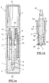
- a device D for dispensing a liquid or pasty product P such as a liquid lipstick.
- This device D comprises a reservoir 1 of product; this reservoir can be constituted by a bottle, in particular made of glass, and it is provided with a neck 2 or neck of a relatively great length, provided with an external thread 21.
- a stopper 4 provided with an internal thread 41 , suitable for cooperating with the thread 21 of the neck 2, is provided for closing the tank.
- the plug 4 comprises, in particular, a transverse wall 42 which is applied in leaktight manner against the end of the neck 2.
- the device D has a longitudinal axis A-A.
- the plug 4 is equipped with an applicator member 7 or end piece, plunging into the reservoir, when the plug is in the closed position as illustrated in FIG. 1a.
- the applicator member 7 is mounted on the lower end 8 of a rod 9, itself integral with the transverse wall 42 of the plug 4 and coaxial with the latter.
- the rod 9 is coaxial with the neck 2 when the plug is in the closed position.
- the applicator member 7 can be made of elastomeric material, flocked plastic material, felt, foam or any other equivalent material which can be impregnated with the product P and suitable for its application.
- the applicator member 7 may have a substantially spherical or ellipsoid shape and a circular, oval or polygonal section.
- the neck 2 of the reservoir is provided with a wiping member 5 of elastically deformable material in which the rod 9 of the applicator member 7 is housed when the cap 4 is fixed on the neck 2 of the reservoir.
- the wiping member 5 consists of two parts: a first cylindrical part constitutes an introduction chimney 52, generally fixed to the neck 2 of the tank; a second part 56 is formed by the internal portion 57 of a torus whose convexity is turned towards the axis A-A of the reservoir.
- This second part has substantially the shape of a diabolo, the upper end 58, facing the neck 2, of the diabolo being secured to the lower edge of the cylindrical chimney 52, the lower end 60 of the diabolo, facing the tank, being free.
- the largest section S of the applicator member is generally of the same order of magnitude as that of the introduction chimney 52, and clearly greater than the section S of large diameter of the rod 9.
- the section S is also significantly greater than the section of the torus 57.
- the wiper member 5 has, at its upper end, a flange 54 projecting radially outward. This flange forms a rim which comes to bear axially against the end of the neck 2. This flange 54 constitutes a seal.
- the wiper member 5 is further provided with one or more slots 59 oriented in the axial direction of the device D and closed at rest. Conversely, when the plug 4 is removed, the slot or slots are open during the extraction phase of the applicator member, as shown in FIG. 1b. The wall 57 of the wiping member is then subjected to a radial thrust force due to the applicator member 7.
- several slots 59 are provided, regularly spaced around the axis (AA) of the device.
- an applicator member 7 of a section S of 40 mm 2 has been chosen; the section of the reduced area is 7 mm 2 ; the rod 9 has a section of 9 mm 2 , and the internal section of the wiper member is 10 mm 2 .
- the pushing force exerted by the applicator member 7 on the internal wall of the wiper member 5 during the extraction phase of the applicator member 7 comprises a component orthogonal to the axis A-A of the reservoir; the applicator member 7 has transverse dimensions such that when it passes through the wiping member, this applicator member 7 causes lateral swelling of the wall 57 and an opening of the slots 59 as illustrated in FIG. 1b.
- FIGS. 1a or 1b illustrate alternative embodiments in which the elements identical or playing roles similar to the elements already described with respect to Figures 1a and 1b are designated by reference numerals identical to those of Figures 1a and 1b, added to one hundred. The same will be done for the variants of the following figures, with progressive increase in the number of hundreds. The elements described in connection with FIGS. 1a or 1b will only be partially taken up.
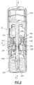
- Figure 2 shows an embodiment of device D similar to that of Figure 1, according to which a wiper member 105 is provided with several longitudinal slots 159, formed in the central part of the diabolo 157.
- the structure of this member d 'spin is distinguished from that of Figure 1 by the presence of a fixing edge 154, folded over the open end of the neck 102 of the tank.
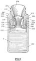
- FIG. 3 shows an alternative embodiment, according to which the attachment of the wiping member 205 to the reservoir 201 is reversed with respect to the embodiment of FIGS. 1a and 1b.
- the open end 202 of the reservoir is surmounted by a wiper element 270 carrying, on the side opposite to the reservoir, a neck 272 provided with an external thread 274 intended to cooperate with a complementary thread of the cap (not shown).
- the neck 272 comprises an introduction chimney 276 of flared conical shape, facilitating the introduction of the applicator member into the tank 201.
- the neck is provided with a radial projection 278 resting on the open end 202 of the tank.
- the projection 278 is connected to a cylindrical portion 280 used for fixing the neck 202 on the reservoir.
- This cylindrical portion 280 carries a cylindrical skirt 282 of smaller thickness, so that a cylindrical volume 284 is formed between the skirt 282 and the reservoir 201.
- a fixing ring (or cylindrical part) 252 is arranged, ring forming an integral part of a wiper member 205.
- This fixing ring 252 is held tight around the skirt 282, thanks to an annular groove 254 / annular bead 286 system.
- the ring 252 is integral with a washer 258 (also forming part of the wiper 205), itself carrying an element 257 in the form of a torus or diabolo portion, this diabolo being turned towards the insertion chimney 276.
- Its free end 260 has approximately the same opening as the neighboring part of the introductory chimney.
- the central part of the diabolo 257 has a series of regularly spaced longitudinal slots 259.
- FIG. 4 shows a variant of a wiping member 305 whose operation is similar to that shown in FIG. 1a.
- This wiper member 305 comprises a cylindrical introduction chimney 352, to which is connected, on the side facing the tank, a diabolo-shaped element 357.
- This element 357 is provided in its internal zone with longitudinal ribs 359, of so that in section along the plane IVa-IVa, as shown in FIG. 4a, this element forms a ring internally shaped in the shape of a star.
- the diabolo 357 is shaped as an annular accordion 357a, comprising alternating internal ribs 359a and external ribs 358a.
- This structure gives the wiper member a particularly high expansion capacity during the passage of the applicator member. This structure thus makes it possible to choose applicator members of dimension even greater than that of the preceding structures.
- FIG. 5 shows a wiping member 505, composed of a cylindrical insertion chimney 552, connected by its end 558 facing the tank, to an element 557 in the form of a diabolo, the thickness of the wall of this diabolo gradually decreasing from its fixed ends 558 and free 560 towards its middle part.
- the expansion capacity of this member 505, during the passage of the applicator member, is similar to that of the previous example.
Abstract
Description
L'invention est relative à un dispositif pour distribuer un produit liquide ou pâteux. Ce dispositif comprend, d'une part, un réservoir pour le produit, muni d'un col portant un organe d'essorage et, d'autre part, un bouchon pour fermer le col du réservoir. Ce bouchon est équipé d'un organe applicateur traversant l'organe d'essorage et plongeant dans le réservoir lorsque le bouchon est en position de fermeture.The invention relates to a device for dispensing a liquid or pasty product. This device comprises, on the one hand, a reservoir for the product, provided with a neck carrying a wiping member and, on the other hand, a cap for closing the neck of the reservoir. This plug is equipped with an applicator member passing through the wiping member and plunging into the reservoir when the plug is in the closed position.
Le produit à appliquer est, par exemple, un produit cosmétique, notamment un produit de maquillage, tel qu'un rouge à lèvres liquide, une ombre à paupières ou un fond de teint.The product to be applied is, for example, a cosmetic product, in particular a makeup product, such as a liquid lipstick, an eye shadow or a foundation.
Avec un tel dispositif, on assure l'imprégnation de l'organe applicateur, lorsque le réservoir est fermé, par exemple en agitant ou en retournant le réservoir de manière à favoriser le contact entre l'organe applicateur et le produit.With such a device, the applicator member is impregnated when the reservoir is closed, for example by agitating or inverting the reservoir so as to promote contact between the applicator member and the product.
Le bouchon est ensuite retiré du réservoir pour permettre l'utilisation de l'organe applicateur imprégné de produit, et l'application du produit à l'endroit souhaité (par exemple les lèvres ou les paupières).The cap is then removed from the reservoir to allow the use of the applicator member impregnated with product, and the application of the product to the desired location (for example the lips or the eyelids).
Lors de la sortie de l'organe applicateur, celui-ci traverse l'organe d'essorage du réservoir pour enlever tout excès de produit de l'organe applicateur.When leaving the applicator member, the latter passes through the wiper member of the reservoir to remove any excess product from the applicator member.
Par les documents US-A-4 332 494 et US-A-3 194 848, on connaît un tel dispositif de distribution de produit liquide ou pâteux. Plus précisément, le dispositif décrit est un distributeur de mascara, dans lequel l'organe d'essorage est conformé en forme de diabolo. Cet essoreur comporte des fentes longitudinales. Un dispositif est en outre prévu pour faire varier la section de l'essoreur à volonté en comprimant celui-ci dans son sens axial. Ceci permet un chargement plus ou moins important de l'organe applicateur.Documents US-A-4,332,494 and US-A-3,194,848 disclose such a device for dispensing a liquid or pasty product. More specifically, the device described is a mascara dispenser, in which the wiper member is shaped like a diabolo. This wringer has longitudinal slots. A device is also provided for varying the section of the wiper at will by compressing it in its axial direction. This allows a more or less significant loading of the applicator member.
Cette réalisation présente l'inconvénient, de ne pas pouvoir comporter un organe applicateur d'une section importante, du fait de la rigidité de l'organe d'essorage sous contrainte. Le fait d'utiliser un applicateur de faible section confère un maquillage inhomogène, comportant des traînés et/ou des surépaisseurs de produit du fait qu'il est nécessaire de repasser plusieurs fois l'applicateur, notamment lorsque la surface à couvrir est importante (lèvres, paupières, joues). De plus, lorsque l'applicateur est une brosse de mascara, un tel organe d'essorage rigide et non dilatable, lors de l'extraction de la brosse hors du réservoir, provoque le pliage des poils de la brosse les uns sur les autres, ce qui a pour conséquences, d'une part un chargement trop faible de la brosse, et d'autre part, un risque d'abîmer la brosse, notamment au cours d'utilisations multiples.This embodiment has the drawback of not being able to include an applicator member of a large section, due to the rigidity of the wiping member under stress. The fact of using an applicator of small section confers an inhomogeneous make-up, comprising streaks and / or extra thicknesses of product because it is necessary to iron the applicator several times, in particular when the surface to be covered is large (lips , eyelids, cheeks). In addition, when the applicator is a mascara brush, such a rigid and non-expandable wiping member, when the brush is extracted from the reservoir, causes the bristles of the brush to bend one on the other, which has the consequences, on the one hand too low a load of the brush, and on the other hand, a risk of damaging the brush, especially during multiple uses.
L'invention a pour but, notamment, de fournir un dispositif, comme défini précédemment pour distribuer un produit liquide ou pâteux qui ne présente pas l'inconvénient ci-dessus. Ainsi, ce dispositif, tout en permettant d'imprégner et de recharger correctement en produit l'organe applicateur, avant l'application du produit, peut être muni d'un organe d'application de section importante.The object of the invention is, in particular, to provide a device, as defined above for dispensing a liquid or pasty product which does not have the above drawback. Thus, this device, while permitting to properly impregnate and reload the product with the applicator member, before the application of the product, can be provided with an applicator member with a large section.
L'invention a donc pour objet, un dispositif pour distribuer un produit liquide ou pâteux comprenant, d'une part, un réservoir de produit ayant un axe longitudinal, surmonté d'un col et muni d'un organe d'essorage réalisé en un matériau élastiquement déformable, et d'autre part, un bouchon pour fermer le col du réservoir, ce bouchon comportant une tige traversant l'organe d'essorage, l'extrémité libre de la tige étant équipée d'un organe applicateur plongeant dans le réservoir lorsque le bouchon est en position de fermeture. Cet organe d'essorage est conformé de sorte que, lors de l'extraction de l'organe applicateur hors du réservoir, l'organe d'essorage essuie d'abord la tige et se dilatant ensuite sous la poussée de l'organe applicateur, cet organe applicateur ayant une section transversale, mesurée perpendiculairement à l'axe, nettement supérieure à celle de la tige.The subject of the invention is therefore, a device for dispensing a liquid or pasty product comprising, on the one hand, a product reservoir having a longitudinal axis, surmounted by a neck and provided with a wiping member produced in a elastically deformable material, and on the other hand, a cap for closing the neck of the reservoir, this cap comprising a rod passing through the wiping member, the free end of the rod being equipped with an applicator member immersed in the reservoir when the cap is in the closed position. This wiper member is shaped so that, when the applicator member is extracted from the reservoir, the wiper member first wipes the rod and then expands under the thrust of the applicator member, this applicator member having a cross section, measured perpendicular to the axis, significantly greater than that of the rod.
De préférence, le rapport de la section de l'organe applicateur/section de la tige, est compris dans la gamme de 4 à 65Preferably, the ratio of the section of the applicator member / section of the rod, is in the range from 4 to 65
Avantageusement, l'organe d'essorage comprend une partie en forme de portion interne d'un tore, dont la convexité est tournée vers l'axe longitudinal du récipient, c'est-à-dire vers la tige, une première des extrémités du tore étant libre. L'organe d'essorage comprend en outre une partie cylindrique de section légèrement supérieure à celle de l'organe d'application, cette partie cylindrique comportant des moyens de fixation sur le col du récipient. De plus, la partie en forme de tore comporte une seconde extrémité fixe, solidaire de la partie cylindrique de l'organe d'essorage.Advantageously, the wiper member comprises a part in the form of an internal portion of a torus, the convexity of which is turned towards the longitudinal axis of the container, that is to say towards the rod, a first of the ends of the torus being free. The wiper member further comprises a cylindrical part of section slightly larger than that of the applicator member, this cylindrical part comprising means for fixing to the neck of the container. In addition, the torus-shaped part has a second fixed end, integral with the cylindrical part of the wiper member.
Selon un premier mode de réalisation, la seconde extrémité libre de la partie en tore se trouve du côté tourné vers le réservoir.According to a first embodiment, the second free end of the toroidal part is on the side facing the reservoir.
Selon un second mode de réalisation, la seconde extrémité libre de la partie en tore se trouve du côté tourné vers le col du réservoir.According to a second embodiment, the second free end of the toroidal part is on the side facing the neck of the reservoir.
La section médiane de la partie en tore peut présenter une section, dans un plan perpendiculaire à l'axe du réservoir, en forme d'anneau.The middle section of the torus portion may have a section, in a plane perpendicular to the axis of the reservoir, in the form of a ring.
Pour augmenter la capacité de dilatation de l'organe d'essorage, la portion interne du tore peut être munie d'au moins une fente longitudinale. Dans ce but; il est possible également, d'agencer sur la portion interne du tore un système de gorges et nervures longitudinales, disposées en quinconce de façon à obtenir une forme d'accordéon. Dans ce cas, la section médiane de la partie en tore présente, dans un plan perpendiculaire à l'axe du réservoir, la forme d'une étoile. Suivant une autre possibilité encore, la paroi de la partie en tore peut avoir une épaisseur dégressive allant de ses extrémités vers sa zone médiane. Ainsi la capacité de dilatation au centre de la partie en tore est maximale.To increase the expansion capacity of the wiping member, the internal portion of the torus can be provided with at least one longitudinal slot. For this reason; it is also possible to arrange on the internal portion of the torus a system of longitudinal grooves and ribs, arranged in staggered rows so as to obtain an accordion shape. In this case, the middle section of the toroidal part has, in a plane perpendicular to the axis of the reservoir, the shape of a star. According to yet another possibility, the wall of the torus portion can have a decreasing thickness going from its ends towards its median zone. Thus, the expansion capacity at the center of the torus part is maximum.
Suivant les dispositions décrites ci-dessus en rapport à l'organe d'essorage, l'effort de poussée exercé par l'organe applicateur sur la paroi torique interne de l'organe d'essorage, en position d'extraction de l'organe applicateur, comprend une composante orthogonale à l'axe du réservoir, cette poussée provoquant un gonflement latéral de la paroi torique de l'essoreur (et ainsi éventuellement l'ouverture de la ou des fentes, lorsqu'elles sont présentes, ou bien l'étirement de l'accordéon), suivi de l'essorage doux de l'organe applicateur.According to the arrangements described above in relation to the wiper member, the thrust force exerted by the applicator member on the internal toric wall of the wiper member, in the member extraction position. applicator, includes a component orthogonal to the axis of the reservoir, this thrust causing a lateral swelling of the toric wall of the wringer (and thus possibly the opening of the slit (s), when they are present, or the stretching of the accordion), followed by gentle wringing of the organ applicator.
Avantageusement, la tige présente une zone de section réduite, située, en position de fermeture du dispositif, à l'intérieur de l'organe d'essorage, de sorte qu'aucune poussée radiale n'est produite sur sa paroi. Cette disposition permet de ne dilater l'organe d'essorage qu'en phase d'extraction de l'organe d'extraction hors du réservoir.Advantageously, the rod has a zone of reduced section, located, in the closed position of the device, inside the wiper member, so that no radial thrust is produced on its wall. This arrangement makes it possible to expand the wiping member only in the extraction phase of the extraction member out of the tank.
Le pouvoir de dilatation de l'organe d'essorage peut être obtenu par l'emploi d'un matériau élastomérique choisi dans le groupe des élastomères de polyéthylène, de polyuréthane, de polyester; des polyéther bloc amides ; des polyvinyles ; des ter-polymères d'éthylène, de propylène et d'un diène (EPDM) ; des polymères de styrène-butadiène séquencés (SEBS-SIS), des silicones, des caoutchoucs nitrile ou naturel.The expansion power of the wiping member can be obtained by the use of an elastomeric material chosen from the group of polyethylene, polyurethane, polyester elastomers; polyether block amides; polyvinyls; ter-polymers of ethylene, propylene and a diene (EPDM); block styrene-butadiene polymers (SEBS-SIS), silicones, nitrile or natural rubbers.
Avantageusement, le matériau pouvant constituer l'organe d'essorage est un matériau dont la capacité de dilatation est de 1 % à 200 %, et de préférence de 20 % à 100 %.Advantageously, the material which can constitute the wiping member is a material whose expansion capacity is from 1% to 200%, and preferably from 20% to 100%.
L'organe applicateur peut être constitué d'un pinceau. De préférence, cet organe applicateur est constitué d'un embout en matériau élastomérique. Ce matériau peut se présenter en forme de mousse. La surface de cet organe applicateur peut être recouvert d'un flocage.The applicator member may consist of a brush. Preferably, this applicator member consists of a tip made of elastomeric material. This material can be in the form of foam. The surface of this applicator member may be covered with a flocking.
Le dispositif conforme à l'invention qui vient d'être décrit convient particulièrement à la distribution et l'application d'un produit liquide pour les lèvres, tel qu'un rouge à lèvres liquide.The device according to the invention which has just been described is particularly suitable for dispensing and applying a liquid product for the lips, such as a liquid lipstick.
L'invention consiste, mises à part les dispositions exposées ci-dessus, en un certain nombre d'autres dispositions dont il sera plus explicitement question ci-après à propos d'exemples de réalisation décrits avec référence aux dessins ci-annexés, mais qui ne sont nullement limitatifs.
- La figure 1a, représente une coupe longitudinale axiale, d'un premier mode d'exécution d'un dispositif selon l'invention.
- La figure 1b est une vue agrandie de l'organe d'essorage de la figure 1, l'organe applicateur étant en cours d'extraction.
- La figure 2 est une vue partielle d'une variante de réalisation du dispositif de la figure 1a.
- Les figures 3 et 4 montrent, en perspective coupée, d'autres variantes de réalisation de l'organe d'essorage de la figure 1a.
- La figure 4a est une coupe selon la ligne IVa-IVa de la figure 4.
- La figure 4b est une variante de réalisation, en coupe selon la ligne IVa-IVa de la figure 4.
- La figure 5 montre, en perspective coupée, une autre variante de réalisation de l'organe d'essorage de la figure 1a.
- Figure 1a shows an axial longitudinal section of a first embodiment of a device according to the invention.
- Figure 1b is an enlarged view of the wiper member of Figure 1, the applicator member being in the process of extraction.
- Figure 2 is a partial view of an alternative embodiment of the device of Figure 1a.
- Figures 3 and 4 show, in cut perspective, other alternative embodiments of the wiper member of Figure 1a.
- FIG. 4a is a section along the line IVa-IVa of FIG. 4.
- FIG. 4b is an alternative embodiment, in section along the line IVa-IVa of FIG. 4.
- Figure 5 shows, in cut perspective, another alternative embodiment of the wiper member of Figure 1a.
En se reportant aux figures 1a et 1b, on peut voir un dispositif D pour distribuer un produit liquide ou pâteux P, tel qu'un rouge à lèvres liquide. Ce dispositif D comprend un réservoir 1 de produit ; ce réservoir peut être constitué par un flacon, notamment en verre, et il est muni d'un col 2 ou goulot d'une longueur relativement importante, muni d'un filetage externe 21. Un bouchon 4, muni d'un filetage interne 41, propre à coopérer avec le filetage 21 du col 2, est prévu pour fermer le réservoir. Le bouchon 4 comporte, notamment, une paroi transversale 42 venant s'appliquer de manière étanche contre l'extrémité du col 2. Le dispositif D présente un axe longitudinal A-A.Referring to Figures 1a and 1b, we can see a device D for dispensing a liquid or pasty product P, such as a liquid lipstick. This device D comprises a
Le bouchon 4 est équipé d'un organe applicateur 7 ou embout, plongeant dans le réservoir, lorsque le bouchon est en position de fermeture comme illustré sur la figure 1a.The
L'organe applicateur 7 est monté sur l'extrémité inférieure 8 d'une tige 9, elle même solidaire de la paroi transversale 42 du bouchon 4 et coaxiale à ce dernier. La tige 9 est coaxiale au col 2 lorsque le bouchon est en position de fermeture.The applicator member 7 is mounted on the
L'organe applicateur 7 peut être réalisé en matière élastomère, en matière plastique floquée, en feutre, en mousse ou en toute autre matière équivalente pouvant s'imprégner du produit P et apte à son application. L'organe applicateur 7 peut avoir une forme sensiblement sphérique ou ellipsoïde et une section circulaire, ovale ou polygonale.The applicator member 7 can be made of elastomeric material, flocked plastic material, felt, foam or any other equivalent material which can be impregnated with the product P and suitable for its application. The applicator member 7 may have a substantially spherical or ellipsoid shape and a circular, oval or polygonal section.
Le col 2 du réservoir est muni d'un organe d'essorage 5 en matière élastiquement déformable dans laquelle vient se loger la tige 9 de l'organe applicateur 7 lorsque le bouchon 4 est fixé sur le col 2 du réservoir. Comme visible, notamment à la figure 1b, l'organe d'essorage 5 est constitué de deux parties : une première partie cylindrique constitue une cheminée d'introduction 52, fixée généralement au col 2 du réservoir ; une seconde partie 56 est constitué par la portion interne 57 d'un tore dont la convexité est tournée vers l'axe A-A du réservoir. Cette seconde partie a sensiblement la forme d'un diabolo, l'extrémité supérieure 58, tournée vers le goulot 2, du diabolo étant solidaire du bord inférieur de la cheminée cylindrique 52, l'extrémité inférieure 60 du diabolo, tournée vers le réservoir, étant libre.The
La plus grande section S de l'organe applicateur est généralement du même ordre de grandeur que celui de la cheminée d'introduction 52, et nettement supérieure à la section s de grand diamètre de la tige 9. La section S est également nettement supérieure à la section du tore 57.The largest section S of the applicator member is generally of the same order of magnitude as that of the
Au niveau où la tige 9 traverse l'organe d'essorage 5, celle-ci présente une section réduite (91), de sorte qu'aucune contrainte n'est exercée par la tige sur l'organe d'essorage en position de repos du dispositif. L'organe d'essorage 5 comporte, à son extrémité supérieure, une collerette 54 faisant saillie radialement vers l'extérieur. Cette collerette forme un rebord qui vient en appui axial contre l'extrémité du col 2. Cette collerette 54 constitue un joint d'étanchéité.At the level where the
L'organe d'essorage 5 est en outre muni d'une ou plusieurs fentes 59 orientées dans le sens axial du dispositif D et fermées au repos. Inversement, lorsque le bouchon 4 est retiré, la ou les fentes sont ouvertes pendant la phase d'extraction de l'organe applicateur, comme montré à la figure 1b. La paroi 57 de l'organe d'essorage est alors soumise à un effort radial de poussée dû à l'organe applicateur 7. Dans l'exemple des figures 1a et 1b, plusieurs fentes 59 sont prévues, régulièrement espacées autour de l'axe (A-A) du dispositif.The
Dans l'exemple considéré, on a choisi un organe applicateur 7 d'une section S de 40 mm2 ; la section de la zone réduite est de 7 mm2 ; la tige 9 a une section de 9 mm2, et la section interne de l'organe d'essorage est de 10mm2. Ces indications sont données à titre indicatif et non limitatif.In the example considered, an applicator member 7 of a section S of 40 mm 2 has been chosen; the section of the reduced area is 7 mm 2 ; the
L'effort de poussée exercé par l'organe applicateur 7 sur la paroi interne de l'organe d'essorage 5 en phase d'extraction de l'organe applicateur 7 comprend une composante orthogonale à l'axe A-A du réservoir ; l'organe applicateur 7 a des dimensions transversales telles que lors de son passage au travers de l'organe d'essorage, cet organe applicateur 7 provoque un gonflement latéral de la paroi 57 et une ouverture des fentes 59 comme illustré sur la figure 1b.The pushing force exerted by the applicator member 7 on the internal wall of the
Les figures 2 et 3 illustrent des variantes de réalisation dans lesquelles les éléments identiques ou jouant des rôles analogues aux éléments déjà décrits à propos des figures 1a et 1b sont désignés par des références numériques identiques à ceux des figures 1a et 1b, additionnées de cent. Il sera procédé de même pour les variantes des figures suivantes, avec augmentation progressive du chiffre des centaines. Les éléments décrits à propos des figures 1a ou 1b ne seront repris que partiellement.Figures 2 and 3 illustrate alternative embodiments in which the elements identical or playing roles similar to the elements already described with respect to Figures 1a and 1b are designated by reference numerals identical to those of Figures 1a and 1b, added to one hundred. The same will be done for the variants of the following figures, with progressive increase in the number of hundreds. The elements described in connection with FIGS. 1a or 1b will only be partially taken up.
Ainsi, la figure 2 montre une réalisation de dispositif D analogue à celui de la figure 1, suivant laquelle un organe d'essorage 105 est muni de plusieurs fentes longitudinales 159, pratiquées dans la partie centrale du diabolo 157. La structure de cet organe d'essorage se distingue de celui de la figure 1 par la présence d'un bord de fixation 154, replié sur l'extrémité ouverte du col 102 du réservoir.Thus, Figure 2 shows an embodiment of device D similar to that of Figure 1, according to which a
La figure 3 montre une variante de réalisation, suivant laquelle la fixation de l'organe d'essorage 205 sur le réservoir 201 est inversé par rapport à la réalisation des figures 1a et 1b. L'extrémité ouverte 202 du réservoir est surmonté d'un élément porte essoreur 270 portant, du coté opposé au réservoir, un goulot 272 muni d'un filetage extérieur 274 destiné à coopérer avec un filetage complémentaire du bouchon (non représenté). Le goulot 272 comporte une cheminée d'introduction 276 de forme conique évasée, facilitant l'introduction de l'organe applicateur dans le réservoir 201. Du côté opposé à la cheminée 276, le goulot est munie d'une saillie radiale 278 reposant sur l'extrémité ouverte 202 du réservoir. A l'intérieur de cette extrémité ouverte, la saillie 278 se raccorde à une portion cylindrique 280 servant à la fixation du goulot 202 sur le réservoir. Cette portion cylindrique 280 porte une jupe cylindrique 282 de plus faible épaisseur, de sorte qu'un volume cylindrique 284 est formé entre la jupe 282 et le réservoir 201. Dans ce volume, une bague de fixation (ou partie cylindrique) 252 est disposée, bague faisant partie intégrale d'un organe d'essorage 205.FIG. 3 shows an alternative embodiment, according to which the attachment of the wiping
Cette bague de fixation 252 est maintenue serrée autour de la jupe 282, grâce à un système gorge annulaire 254/bourrelet annulaire 286. Du côté tourné vers le réservoir, la bague 252 est solidaire d'une rondelle 258 (faisant aussi partie de l'organe d'essorage 205), portant elle-même un élément 257 en forme de portion de tore ou diabolo, ce diabolo étant tourné vers la cheminée d'introduction 276. Son extrémité libre 260 a approximativement la même ouverture que la partie avoisinante de la cheminée d'introduction.This fixing
La partie centrale du diabolo 257 comporte une série de fentes longitudinales 259 régulièrement espacées.The central part of the
La figure 4 montre une variante d'organe d'essorage 305 dont le fonctionnement est analogue à celui représenté à la figure 1a. Cet organe d'essorage 305 comporte une cheminée d'introduction cylindrique 352, à laquelle est raccordée, du côté tourné vers le réservoir, un élément en forme de diabolo 357. Cet élément 357 est muni dans sa zone interne de nervures longitudinales 359, de sorte que en coupe selon le plan IVa-IVa, comme représenté à la figure 4a, cet élément forme un anneau conformé intérieurement en forme d'étoile.FIG. 4 shows a variant of a wiping
Selon une autre variante, représentée à la figure 4b, le diabolo 357 est conformé en accordéon annulaire 357a, comportant des nervures internes 359a et externes 358a alternées. Celle structure confère à l'organe d'essorage une capacité de dilatation particulièrement élevée lors du passage de l'organe applicateur. Cette structure permet ainsi de choisir des organes applicateurs de dimension encore supérieure à celle des structures précédentes.According to another variant, shown in FIG. 4b, the
La figure 5 montre un organe d'essorage 505, composé d'une cheminée d'introduction cylindrique 552, se raccordant par son extrémité 558 tournée vers le réservoir, à un élément 557 en forme de diabolo, l'épaisseur de la paroi de ce diabolo diminuant progressivement de ses extrémités fixe 558 et libre 560 vers sa partie médiane. La capacité de dilatation de cet organe 505, lors du passage de l'organe applicateur, est analogue à celle de l'exemple précédent.FIG. 5 shows a wiping
Claims (18)
Applications Claiming Priority (2)
| Application Number | Priority Date | Filing Date | Title |
|---|---|---|---|
| FR9502197 | 1995-02-24 | ||
| FR9502197A FR2730911B1 (en) | 1995-02-24 | 1995-02-24 | DEVICE FOR DISPENSING A LIQUID OR PULVERULENT PRODUCT COMPRISING A WRINKING MEMB |
Publications (2)
| Publication Number | Publication Date |
|---|---|
| EP0728426A1 true EP0728426A1 (en) | 1996-08-28 |
| EP0728426B1 EP0728426B1 (en) | 1998-04-01 |
Family
ID=9476495
Family Applications (1)
| Application Number | Title | Priority Date | Filing Date |
|---|---|---|---|
| EP96400184A Expired - Lifetime EP0728426B1 (en) | 1995-02-24 | 1996-01-25 | Dispensing device for a liquid or pasty product with a wiping element |
Country Status (10)
| Country | Link |
|---|---|
| US (1) | US5803638A (en) |
| EP (1) | EP0728426B1 (en) |
| AR (1) | AR000996A1 (en) |
| AT (1) | ATE164496T1 (en) |
| BR (1) | BR9600618A (en) |
| CA (1) | CA2170193C (en) |
| DE (1) | DE69600207T2 (en) |
| ES (1) | ES2119548T3 (en) |
| FR (1) | FR2730911B1 (en) |
| MX (1) | MX9600703A (en) |
Cited By (8)
| Publication number | Priority date | Publication date | Assignee | Title |
|---|---|---|---|---|
| US6659391B1 (en) | 1999-04-30 | 2003-12-09 | Kimberly-Clark Worldwide, Inc. | Method for dispensing wet wipes |
| EP1752061A1 (en) | 2005-08-11 | 2007-02-14 | Geka Brush Gmbh | Applicator for a cosmetic produkt |
| FR2918255A1 (en) * | 2007-07-05 | 2009-01-09 | Chanel Parfums Beaute Sas Unip | MAKE-UP DEVICE COMPRISING A SWEEPER |
| FR2939413A1 (en) * | 2008-12-08 | 2010-06-11 | Oreal | Packaging assembly for e.g. cosmetic product, has insert whose lateral projection is engaged in through opening of neck of bottle to retain insert in neck, where insert is assembled in neck to create sealed junction between neck and insert |
| FR2951920A1 (en) * | 2009-11-04 | 2011-05-06 | Oreal | DEVICE FOR CONDITIONING AND APPLYING A COSMETIC PRODUCT ON LIP. |
| CN101217898B (en) * | 2005-07-06 | 2011-09-07 | 欧莱雅 | A packaging and applicator device including a wiper member |
| EP1920677B1 (en) * | 2006-11-09 | 2014-01-08 | GEKA GmbH | Applicator for a cosmetic product for the lips |
| WO2019129935A1 (en) * | 2017-12-29 | 2019-07-04 | Simp | Wiper device for an applicator for a cosmetic product |
Families Citing this family (44)
| Publication number | Priority date | Publication date | Assignee | Title |
|---|---|---|---|---|
| US5088327A (en) * | 1990-05-17 | 1992-02-18 | The United States Of America As Represented By The Secretary Of The Navy | Phase cancellation enhancement of ultrasonic evaluation of metal-to-elastomer bonding |
| FR2745481B1 (en) | 1996-02-29 | 1998-04-30 | Oreal | PROGRESSIVE BRUSH FOR APPLYING A COSMETIC PRODUCT, ESPECIALLY MASCARA |
| FR2749489B1 (en) | 1996-06-07 | 1998-08-07 | Oreal | PLAN-CONVEX PROFILE BRUSH |
| FR2753058B1 (en) * | 1996-09-10 | 1998-10-16 | Oreal | LIQUID OR SEMI-LIQUID APPLICATION ASSEMBLY |
| FR2753057B1 (en) * | 1996-09-10 | 1998-10-16 | Oreal | LIQUID OR SEMI-LIQUID APPLICATION ASSEMBLY |
| USRE38397E1 (en) | 1996-11-13 | 2004-01-27 | L'oreal | Brush for applying a cosmetic product and make-up device comprising it |
| FR2762494B1 (en) * | 1997-04-28 | 1999-06-25 | Oreal | APPLICATOR AND PACKAGING AND APPLICATION ASSEMBLY USING SUCH AN APPLICATOR |
| FR2767040B1 (en) * | 1997-08-07 | 1999-09-24 | Oreal | DEVICE FOR THE TREATMENT AND / OR MAKE-UP OF KERATINIC FIBERS |
| US6702227B1 (en) | 1999-04-30 | 2004-03-09 | Kimberly-Clark Worldwide, Inc. | Wipes dispensing system |
| US6705565B1 (en) | 1999-04-30 | 2004-03-16 | Kimberly-Clark Worldwide, Inc. | System and dispenser for dispensing wet wipes |
| US6537631B1 (en) | 1999-04-30 | 2003-03-25 | Kimberly-Clark Worldwide, Inc. | Roll of wet wipes |
| US6238116B1 (en) | 1999-04-30 | 2001-05-29 | Bic Corporation | Foam applicator with wiper insert |
| FR2793663B1 (en) * | 1999-05-19 | 2001-08-03 | Oreal | DEVICE FOR PACKAGING AND APPLYING A COSMETIC PRODUCT, PARTICULARLY FOR MAKING LIP |
| US6732743B1 (en) * | 1999-07-22 | 2004-05-11 | Color Access, Inc. | Flocked cosmetic applicator |
| FR2821532B1 (en) | 2001-03-01 | 2003-12-12 | Oreal | BRUSH FOR APPLYING A PRODUCT ON KERATINIC FIBERS |
| FR2821533B1 (en) | 2001-03-01 | 2004-01-23 | Oreal | BRUSH FOR APPLYING A PRODUCT ON KERATINIC FIBERS |
| FR2821536B1 (en) | 2001-03-01 | 2003-05-16 | Oreal | BRUSH FOR APPLYING A PRODUCT ON KERATINIC FIBERS |
| US6779657B2 (en) | 2001-06-06 | 2004-08-24 | Closure Medical Corporation | Single-use applicators, dispensers and methods for polymerizable monomer compound |
| WO2003016834A1 (en) | 2001-08-16 | 2003-02-27 | Closure Medical Corporation | Multiple-component combining |
| JP2003310346A (en) * | 2002-04-23 | 2003-11-05 | Mitsubishi Pencil Co Ltd | Liquid container |
| FR2855380B1 (en) | 2003-05-27 | 2006-09-15 | Oreal | DEVICE FOR PACKAGING AND APPLYING A PRODUCT, COMPRISING A SPINNING ORGAN |
| US7967519B2 (en) | 2003-05-27 | 2011-06-28 | L'oreal | Device for packaging and applying a substance, the device including a wiper member |
| US20050109365A1 (en) * | 2003-06-03 | 2005-05-26 | Dunton David P. | Unitary flocked cosmetics applicator |
| FR2865911B1 (en) * | 2004-02-06 | 2008-01-25 | Oreal | PACKAGING AND APPLICATION DEVICE HAVING A SPINNING BODY |
| FR2867957B1 (en) * | 2004-03-25 | 2006-07-14 | Oreal | DEVICE FOR PACKAGING AND APPLYING A PRODUCT, IN PARTICULAR COSMETIC |
| US7350997B2 (en) * | 2004-03-25 | 2008-04-01 | L'oreal | Packaging and applicator device for applying a substance, in particular a cosmetic |
| BRPI0400438A (en) * | 2004-04-07 | 2005-11-22 | Botica Com Farmaceutica Ltda | Oily suspension cosmetic composition |
| FR2872999B1 (en) * | 2004-07-13 | 2007-09-07 | Oreal | DEVICE FOR PACKAGING AND APPLYING A COSMETIC OR CARE PRODUCT |
| US7914220B2 (en) * | 2005-03-01 | 2011-03-29 | Elc Management Llc | Vented mascara wiper |
| FR2884397B1 (en) * | 2005-04-19 | 2007-07-06 | Parfums Givenchy Sa | PERFECTIONED MASCARA APPLICATOR |
| DE602006004912D1 (en) * | 2005-04-25 | 2009-03-12 | Oreal | Packaging and application device of a cosmetic product |
| US7918619B2 (en) * | 2005-05-24 | 2011-04-05 | L'oreal | Packaging and applicator device, and method of making up skin or lips |
| US7624868B2 (en) * | 2005-12-01 | 2009-12-01 | Cook Vascular Incorporated | Pipette holder |
| US7223035B1 (en) * | 2005-12-16 | 2007-05-29 | Access Business Group International Llc | Device for containing and applying cosmetics |
| US20080103426A1 (en) * | 2006-10-25 | 2008-05-01 | Cao Group, Inc. | Unit Dose Delivery Systems Using Brushes |
| FR2936939B1 (en) * | 2008-10-13 | 2010-10-01 | Chanel Parfums Beaute | BOTTLE FOR LIQUID OR PASTY COSMETIC PRODUCT WITH REMOVABLE APPLICATION ELEMENT |
| FR2936938B1 (en) * | 2008-10-13 | 2012-12-14 | Chanel Parfums Beaute | TELESCOPIC BOTTLE FOR LIQUID OR PASTY COSMETIC PRODUCT |
| US20100266327A1 (en) * | 2009-04-21 | 2010-10-21 | Ching Lang Lin | Applicator device for a cosmetic product |
| KR200464718Y1 (en) | 2010-11-30 | 2013-01-17 | (주)아모레퍼시픽 | Manicure case |
| WO2017075816A1 (en) * | 2015-11-06 | 2017-05-11 | 陈文胜 | Cosmetics container |
| US10117498B2 (en) | 2016-11-23 | 2018-11-06 | Albea Cosmetics America, INC | Reservoir for a viscous or liquid cosmetic product and an assembly comprising a cosmetic applicator |
| USD957051S1 (en) * | 2018-07-27 | 2022-07-05 | L'oreal | Eyeliner |
| CN110934410B (en) * | 2019-11-29 | 2022-06-14 | 上海容奥包装科技有限公司 | Mascara device |
| WO2023235931A1 (en) * | 2022-06-10 | 2023-12-14 | Zeyrro Pty Ltd | An applicator bottle |
Citations (8)
| Publication number | Priority date | Publication date | Assignee | Title |
|---|---|---|---|---|
| US2627619A (en) * | 1947-07-29 | 1953-02-10 | Gagen Joseph Wilfrid | Nail lacquer bottle assembly, including brush wiper |
| US3194848A (en) | 1962-12-31 | 1965-07-13 | Nat Distillers Chem Corp | Process for dimer and trimer preparation |
| US3662769A (en) * | 1970-10-05 | 1972-05-16 | Bridgeport Metal Goods Mfg Co | Cosmetic applicator |
| US3896823A (en) * | 1974-02-01 | 1975-07-29 | Spatz Corp | Cosmetic applicator |
| US3921650A (en) * | 1974-12-23 | 1975-11-25 | Max Factor & Co | Cosmetic applicator and container |
| FR2285101A1 (en) * | 1974-09-23 | 1976-04-16 | Bellon Labor Sa Roger | Container and applicator stick for powdery makeup - are fitted with foam collar round stick to wipe off excess powder |
| US4332494A (en) | 1977-12-05 | 1982-06-01 | Plough, Inc. | Adjustable cosmetic wiper |
| DE4216525A1 (en) * | 1992-05-19 | 1993-11-25 | Geka Brush Georg Karl Gmbh | Eyelash mascara applicator with handle and container forming unit - has empty cavity connected to storage container for disinfectant, semi permeable membrane and wiper sealing parts |
Family Cites Families (7)
| Publication number | Priority date | Publication date | Assignee | Title |
|---|---|---|---|---|
| US185693A (en) * | 1876-12-26 | Improvement in blacking-bottles | ||
| US3214782A (en) * | 1964-01-16 | 1965-11-02 | Helen Rubinstein Inc | Mascara applicator |
| DE2722232A1 (en) * | 1977-05-17 | 1978-11-30 | Dahm Klaus Peter | Nail lacquer bottle applicator - has brush inserted in lid with fan shaped multi-level flaps for drop retention |
| US4403624A (en) * | 1981-09-25 | 1983-09-13 | Montgomery Robin M | Cosmetic applicator and container system |
| US4390298A (en) * | 1981-10-21 | 1983-06-28 | Carluccio John F | Universal wiper plug for liquid cosmetic products |
| FR2545008A1 (en) * | 1983-04-27 | 1984-11-02 | Snap Duroc Sa | Fluid-substance applicator with adjustable drying |
| JP3086915B2 (en) * | 1993-02-26 | 2000-09-11 | 鐘紡株式会社 | Storage container for liquid cosmetics, etc. |
-
1995
- 1995-02-24 FR FR9502197A patent/FR2730911B1/en not_active Expired - Fee Related
-
1996
- 1996-01-25 EP EP96400184A patent/EP0728426B1/en not_active Expired - Lifetime
- 1996-01-25 ES ES96400184T patent/ES2119548T3/en not_active Expired - Lifetime
- 1996-01-25 AT AT96400184T patent/ATE164496T1/en not_active IP Right Cessation
- 1996-01-25 DE DE69600207T patent/DE69600207T2/en not_active Expired - Lifetime
- 1996-02-21 AR ARP960101457A patent/AR000996A1/en unknown
- 1996-02-22 MX MX9600703A patent/MX9600703A/en unknown
- 1996-02-23 CA CA002170193A patent/CA2170193C/en not_active Expired - Fee Related
- 1996-02-23 US US08/606,406 patent/US5803638A/en not_active Expired - Lifetime
- 1996-02-26 BR BR9600618A patent/BR9600618A/en not_active IP Right Cessation
Patent Citations (8)
| Publication number | Priority date | Publication date | Assignee | Title |
|---|---|---|---|---|
| US2627619A (en) * | 1947-07-29 | 1953-02-10 | Gagen Joseph Wilfrid | Nail lacquer bottle assembly, including brush wiper |
| US3194848A (en) | 1962-12-31 | 1965-07-13 | Nat Distillers Chem Corp | Process for dimer and trimer preparation |
| US3662769A (en) * | 1970-10-05 | 1972-05-16 | Bridgeport Metal Goods Mfg Co | Cosmetic applicator |
| US3896823A (en) * | 1974-02-01 | 1975-07-29 | Spatz Corp | Cosmetic applicator |
| FR2285101A1 (en) * | 1974-09-23 | 1976-04-16 | Bellon Labor Sa Roger | Container and applicator stick for powdery makeup - are fitted with foam collar round stick to wipe off excess powder |
| US3921650A (en) * | 1974-12-23 | 1975-11-25 | Max Factor & Co | Cosmetic applicator and container |
| US4332494A (en) | 1977-12-05 | 1982-06-01 | Plough, Inc. | Adjustable cosmetic wiper |
| DE4216525A1 (en) * | 1992-05-19 | 1993-11-25 | Geka Brush Georg Karl Gmbh | Eyelash mascara applicator with handle and container forming unit - has empty cavity connected to storage container for disinfectant, semi permeable membrane and wiper sealing parts |
Cited By (14)
| Publication number | Priority date | Publication date | Assignee | Title |
|---|---|---|---|---|
| US6659391B1 (en) | 1999-04-30 | 2003-12-09 | Kimberly-Clark Worldwide, Inc. | Method for dispensing wet wipes |
| CN101217898B (en) * | 2005-07-06 | 2011-09-07 | 欧莱雅 | A packaging and applicator device including a wiper member |
| US8221015B2 (en) | 2005-07-06 | 2012-07-17 | L'oreal | Packaging and applicator device including a wiper member |
| EP1752061A1 (en) | 2005-08-11 | 2007-02-14 | Geka Brush Gmbh | Applicator for a cosmetic produkt |
| EP1920677B1 (en) * | 2006-11-09 | 2014-01-08 | GEKA GmbH | Applicator for a cosmetic product for the lips |
| WO2009007650A2 (en) * | 2007-07-05 | 2009-01-15 | Chanel Parfums Beaute | Makeup device including a squeegee |
| WO2009007650A3 (en) * | 2007-07-05 | 2009-04-09 | Chanel Parfums Beaute | Makeup device including a squeegee |
| US8221013B2 (en) | 2007-07-05 | 2012-07-17 | Chanel Parfums Beaute | Makeup device including a wiper |
| FR2918255A1 (en) * | 2007-07-05 | 2009-01-09 | Chanel Parfums Beaute Sas Unip | MAKE-UP DEVICE COMPRISING A SWEEPER |
| FR2939413A1 (en) * | 2008-12-08 | 2010-06-11 | Oreal | Packaging assembly for e.g. cosmetic product, has insert whose lateral projection is engaged in through opening of neck of bottle to retain insert in neck, where insert is assembled in neck to create sealed junction between neck and insert |
| FR2951920A1 (en) * | 2009-11-04 | 2011-05-06 | Oreal | DEVICE FOR CONDITIONING AND APPLYING A COSMETIC PRODUCT ON LIP. |
| WO2011055299A1 (en) * | 2009-11-04 | 2011-05-12 | L'oreal | A packaging and applicator device for applying a cosmetic composition to the lips |
| US10010151B2 (en) | 2009-11-04 | 2018-07-03 | L'oreal S.A. | Packaging and applicator device for applying a cosmetic composition to the lips |
| WO2019129935A1 (en) * | 2017-12-29 | 2019-07-04 | Simp | Wiper device for an applicator for a cosmetic product |
Also Published As
| Publication number | Publication date |
|---|---|
| US5803638A (en) | 1998-09-08 |
| MX9600703A (en) | 1997-02-28 |
| DE69600207D1 (en) | 1998-05-07 |
| EP0728426B1 (en) | 1998-04-01 |
| ATE164496T1 (en) | 1998-04-15 |
| FR2730911B1 (en) | 1997-04-04 |
| DE69600207T2 (en) | 1998-07-23 |
| AR000996A1 (en) | 1997-08-27 |
| BR9600618A (en) | 1997-12-30 |
| CA2170193C (en) | 1999-06-15 |
| FR2730911A1 (en) | 1996-08-30 |
| ES2119548T3 (en) | 1998-10-01 |
| CA2170193A1 (en) | 1996-08-25 |
Similar Documents
| Publication | Publication Date | Title |
|---|---|---|
| EP0728426B1 (en) | Dispensing device for a liquid or pasty product with a wiping element | |
| CA2141662C (en) | Device for dispensing liquid or pulverulent products | |
| EP1053695B2 (en) | Device for storing and applying cosmetic products, especially for lipsticks | |
| EP1050231B1 (en) | Device for storing and applying cosmetic products | |
| EP0916282B1 (en) | Device for storing and applying,including a container,an ergonomic applicator and a wiper | |
| CA2169613C (en) | Capillary feeder with terminal slot | |
| EP1199004B1 (en) | Packaging and application device, and reloading element therefor | |
| EP0829211B1 (en) | Device for storing and applying a liquid or semi-liquid product | |
| EP0549780B1 (en) | Applicator assembly for liquid, particularly cosmetic, composition | |
| CA2389875C (en) | Easy-assembly wiper | |
| FR2888097A1 (en) | Applicator device for packaging and applying cosmetic product or care product, has wiper lip undulated to enable the wiper lip to deploy under thrust from applicator brush | |
| FR2932168A1 (en) | PACKAGING AND APPLICATION DEVICE | |
| CA2044519A1 (en) | Pasty cosmetic product applicator | |
| EP0940103B1 (en) | Stick holder cup and package for a make-up product comprising such a cup | |
| CA2251621C (en) | Lipstick holder and lipstick case comprising same | |
| EP1797790B1 (en) | Device for storing and applying comprising an adjustable wiping element | |
| FR3016274A1 (en) | SPINNING DEVICE WITH VARIABLE GEOMETRY WIPING LIP | |
| FR3089768A1 (en) | Wringing device for a device for packaging and applying a cosmetic product | |
| EP3731695B1 (en) | Wiper device for an applicator for a cosmetic product | |
| FR2563712A1 (en) | Make-up assembly, particularly for the eyelashes, making it possible to withdraw a predetermined quantity of make-up product | |
| FR2867957A1 (en) | DEVICE FOR PACKAGING AND APPLYING A PRODUCT, IN PARTICULAR COSMETIC | |
| FR2769808A1 (en) | Applicator for cosmetic product such as mascara | |
| FR3070838A1 (en) | APPLICATOR FOR APPLYING A COSMETIC PRODUCT | |
| FR2908273A1 (en) | Cosmetic product i.e. mascara, applicator for eyelash, has external sheath surrounding internal central part such that part and sheath freely turn around common axis, where sheath is received inside bore of rod and part is hooked to core |
Legal Events
| Date | Code | Title | Description |
|---|---|---|---|
| PUAI | Public reference made under article 153(3) epc to a published international application that has entered the european phase |
Free format text: ORIGINAL CODE: 0009012 |
|
| AK | Designated contracting states |
Kind code of ref document: A1 Designated state(s): AT BE CH DE DK ES FR GB GR IE IT LI LU MC NL PT SE |
|
| 17P | Request for examination filed |
Effective date: 19960722 |
|
| 17Q | First examination report despatched |
Effective date: 19960923 |
|
| GRAG | Despatch of communication of intention to grant |
Free format text: ORIGINAL CODE: EPIDOS AGRA |
|
| GRAG | Despatch of communication of intention to grant |
Free format text: ORIGINAL CODE: EPIDOS AGRA |
|
| GRAG | Despatch of communication of intention to grant |
Free format text: ORIGINAL CODE: EPIDOS AGRA |
|
| GRAH | Despatch of communication of intention to grant a patent |
Free format text: ORIGINAL CODE: EPIDOS IGRA |
|
| GRAH | Despatch of communication of intention to grant a patent |
Free format text: ORIGINAL CODE: EPIDOS IGRA |
|
| GRAA | (expected) grant |
Free format text: ORIGINAL CODE: 0009210 |
|
| AK | Designated contracting states |
Kind code of ref document: B1 Designated state(s): AT BE CH DE DK ES FR GB GR IE IT LI LU MC NL PT SE |
|
| PG25 | Lapsed in a contracting state [announced via postgrant information from national office to epo] |
Ref country code: NL Free format text: LAPSE BECAUSE OF FAILURE TO SUBMIT A TRANSLATION OF THE DESCRIPTION OR TO PAY THE FEE WITHIN THE PRESCRIBED TIME-LIMIT Effective date: 19980401 Ref country code: GR Free format text: LAPSE BECAUSE OF NON-PAYMENT OF DUE FEES Effective date: 19980401 Ref country code: AT Free format text: LAPSE BECAUSE OF FAILURE TO SUBMIT A TRANSLATION OF THE DESCRIPTION OR TO PAY THE FEE WITHIN THE PRESCRIBED TIME-LIMIT Effective date: 19980401 |
|
| REF | Corresponds to: |
Ref document number: 164496 Country of ref document: AT Date of ref document: 19980415 Kind code of ref document: T |
|
| ITF | It: translation for a ep patent filed |
Owner name: JACOBACCI & PERANI S.P.A. |
|
| REG | Reference to a national code |
Ref country code: CH Ref legal event code: EP |
|
| GBT | Gb: translation of ep patent filed (gb section 77(6)(a)/1977) |
Effective date: 19980402 |
|
| REF | Corresponds to: |
Ref document number: 69600207 Country of ref document: DE Date of ref document: 19980507 |
|
| PG25 | Lapsed in a contracting state [announced via postgrant information from national office to epo] |
Ref country code: SE Free format text: LAPSE BECAUSE OF FAILURE TO SUBMIT A TRANSLATION OF THE DESCRIPTION OR TO PAY THE FEE WITHIN THE PRESCRIBED TIME-LIMIT Effective date: 19980701 Ref country code: PT Free format text: LAPSE BECAUSE OF FAILURE TO SUBMIT A TRANSLATION OF THE DESCRIPTION OR TO PAY THE FEE WITHIN THE PRESCRIBED TIME-LIMIT Effective date: 19980701 Ref country code: DK Free format text: LAPSE BECAUSE OF FAILURE TO SUBMIT A TRANSLATION OF THE DESCRIPTION OR TO PAY THE FEE WITHIN THE PRESCRIBED TIME-LIMIT Effective date: 19980701 |
|
| REG | Reference to a national code |
Ref country code: IE Ref legal event code: FG4D Free format text: 79638 |
|
| NLV1 | Nl: lapsed or annulled due to failure to fulfill the requirements of art. 29p and 29m of the patents act | ||
| REG | Reference to a national code |
Ref country code: ES Ref legal event code: FG2A Ref document number: 2119548 Country of ref document: ES Kind code of ref document: T3 |
|
| PG25 | Lapsed in a contracting state [announced via postgrant information from national office to epo] |
Ref country code: IE Free format text: LAPSE BECAUSE OF NON-PAYMENT OF DUE FEES Effective date: 19981023 |
|
| REG | Reference to a national code |
Ref country code: IE Ref legal event code: FD4D Ref document number: 79638 Country of ref document: IE |
|
| PG25 | Lapsed in a contracting state [announced via postgrant information from national office to epo] |
Ref country code: LU Free format text: LAPSE BECAUSE OF NON-PAYMENT OF DUE FEES Effective date: 19990125 |
|
| PG25 | Lapsed in a contracting state [announced via postgrant information from national office to epo] |
Ref country code: BE Free format text: LAPSE BECAUSE OF NON-PAYMENT OF DUE FEES Effective date: 19990131 |
|
| PLBE | No opposition filed within time limit |
Free format text: ORIGINAL CODE: 0009261 |
|
| STAA | Information on the status of an ep patent application or granted ep patent |
Free format text: STATUS: NO OPPOSITION FILED WITHIN TIME LIMIT |
|
| 26N | No opposition filed | ||
| BERE | Be: lapsed |
Owner name: L' OREAL Effective date: 19990131 |
|
| PG25 | Lapsed in a contracting state [announced via postgrant information from national office to epo] |
Ref country code: MC Free format text: LAPSE BECAUSE OF NON-PAYMENT OF DUE FEES Effective date: 19990731 |
|
| PG25 | Lapsed in a contracting state [announced via postgrant information from national office to epo] |
Ref country code: LI Free format text: LAPSE BECAUSE OF NON-PAYMENT OF DUE FEES Effective date: 20000131 Ref country code: CH Free format text: LAPSE BECAUSE OF NON-PAYMENT OF DUE FEES Effective date: 20000131 |
|
| REG | Reference to a national code |
Ref country code: CH Ref legal event code: PL |
|
| REG | Reference to a national code |
Ref country code: GB Ref legal event code: IF02 |
|
| PGFP | Annual fee paid to national office [announced via postgrant information from national office to epo] |
Ref country code: ES Payment date: 20100128 Year of fee payment: 15 |
|
| PGFP | Annual fee paid to national office [announced via postgrant information from national office to epo] |
Ref country code: IT Payment date: 20100120 Year of fee payment: 15 Ref country code: FR Payment date: 20100208 Year of fee payment: 15 |
|
| PGFP | Annual fee paid to national office [announced via postgrant information from national office to epo] |
Ref country code: GB Payment date: 20100120 Year of fee payment: 15 Ref country code: DE Payment date: 20100121 Year of fee payment: 15 |
|
| GBPC | Gb: european patent ceased through non-payment of renewal fee |
Effective date: 20110125 |
|
| REG | Reference to a national code |
Ref country code: FR Ref legal event code: ST Effective date: 20110930 |
|
| PG25 | Lapsed in a contracting state [announced via postgrant information from national office to epo] |
Ref country code: FR Free format text: LAPSE BECAUSE OF NON-PAYMENT OF DUE FEES Effective date: 20110131 |
|
| PG25 | Lapsed in a contracting state [announced via postgrant information from national office to epo] |
Ref country code: GB Free format text: LAPSE BECAUSE OF NON-PAYMENT OF DUE FEES Effective date: 20110125 |
|
| REG | Reference to a national code |
Ref country code: DE Ref legal event code: R119 Ref document number: 69600207 Country of ref document: DE Effective date: 20110802 |
|
| PG25 | Lapsed in a contracting state [announced via postgrant information from national office to epo] |
Ref country code: IT Free format text: LAPSE BECAUSE OF NON-PAYMENT OF DUE FEES Effective date: 20110125 |
|
| REG | Reference to a national code |
Ref country code: ES Ref legal event code: FD2A Effective date: 20120220 |
|
| PG25 | Lapsed in a contracting state [announced via postgrant information from national office to epo] |
Ref country code: ES Free format text: LAPSE BECAUSE OF NON-PAYMENT OF DUE FEES Effective date: 20110126 |
|
| PG25 | Lapsed in a contracting state [announced via postgrant information from national office to epo] |
Ref country code: DE Free format text: LAPSE BECAUSE OF NON-PAYMENT OF DUE FEES Effective date: 20110802 |