EP0728422A1 - Self-contained automatic citric juice extracting and dispensing machine - Google Patents
Self-contained automatic citric juice extracting and dispensing machine Download PDFInfo
- Publication number
- EP0728422A1 EP0728422A1 EP94925489A EP94925489A EP0728422A1 EP 0728422 A1 EP0728422 A1 EP 0728422A1 EP 94925489 A EP94925489 A EP 94925489A EP 94925489 A EP94925489 A EP 94925489A EP 0728422 A1 EP0728422 A1 EP 0728422A1
- Authority
- EP
- European Patent Office
- Prior art keywords
- citric
- juice
- units
- juice extracting
- unit
- Prior art date
- Legal status (The legal status is an assumption and is not a legal conclusion. Google has not performed a legal analysis and makes no representation as to the accuracy of the status listed.)
- Ceased
Links
Images


Classifications
-
- G—PHYSICS
- G07—CHECKING-DEVICES
- G07F—COIN-FREED OR LIKE APPARATUS
- G07F13/00—Coin-freed apparatus for controlling dispensing or fluids, semiliquids or granular material from reservoirs
- G07F13/06—Coin-freed apparatus for controlling dispensing or fluids, semiliquids or granular material from reservoirs with selective dispensing of different fluids or materials or mixtures thereof
- G07F13/065—Coin-freed apparatus for controlling dispensing or fluids, semiliquids or granular material from reservoirs with selective dispensing of different fluids or materials or mixtures thereof for drink preparation
-
- A—HUMAN NECESSITIES
- A23—FOODS OR FOODSTUFFS; TREATMENT THEREOF, NOT COVERED BY OTHER CLASSES
- A23N—MACHINES OR APPARATUS FOR TREATING HARVESTED FRUIT, VEGETABLES OR FLOWER BULBS IN BULK, NOT OTHERWISE PROVIDED FOR; PEELING VEGETABLES OR FRUIT IN BULK; APPARATUS FOR PREPARING ANIMAL FEEDING- STUFFS
- A23N1/00—Machines or apparatus for extracting juice
- A23N1/003—Machines or apparatus for extracting juice especially for citrus fruits
-
- G—PHYSICS
- G07—CHECKING-DEVICES
- G07F—COIN-FREED OR LIKE APPARATUS
- G07F13/00—Coin-freed apparatus for controlling dispensing or fluids, semiliquids or granular material from reservoirs
Definitions
- This invention deals with presenting a citric juice extracting system within the framework of a public dispensing machine.
- citric juice extractors wit electric-electronic control, ever since the appearance of the first domestic robots of small size which gave an axis the necessary rotational force to rub against the inside of the citric fruit, situated over the axis of a body which dealt with pressing and dragging as it turned the inside of the citric fruit which was held firm over the said body, straining the juice produced by the said action through the base of the said juice extracting unit.
- This mechanism was controlled by pushing a button, later evolving to a system where it was only necessary to press the citrus fruit vertically upon the revolving extracting body, which had two stable positions, and upper, stop, position, and a lower one driving the axis.
- citric fruit preferably of diameters between 86 and 80 millimetres may be stored; approximately 384 pieces of fruit may be stored, while all the interior devices are fitted inside an external casing of similar dimensions to coffee or canned soft drink dispensers.
- the machine consists of a series of modules which, once assembled, allow, by the insertion of coins for its operation, having placed pieces of citric fruit in the corresponding internal stores, a cup of citric juice to be obtained from the machine.
- the module identified as (1) will be the money mechanism, which (1) allows the possibility of using the machine subject of this invention either by inserting coins into the device (1a) or by inserting the user's credit card into the device (1b).
- the acceptance of coins or credit cards will be supervised by an electronic controller (3), which, like the rest of the control devices, will consist of a PC-type computer, to be described below.
- the said electronic controller (3) will also control the electronic supply equipment which will supply the various devices contained within the system.
- citric unit container module (4) which consists of a frame (41) of stainless steel with finishing surface treatment and plastic finishing, which bear an alternating grid of 48 tubes (42) manufactured in PVC, preferable of a diameter of 90 millimetres, with a preferable length of 640 millimetres, as can be seen in Figure 4.
- the tubes are fixed together with contact adhesive (43), which avoids any relative displacement between them.
- the module (5) or citric unit dispenser, has been located in the machine, the contents of which are explained in greater detail in Figures 5 and 6; this consists of two bands of reinforced PVC, the preferable dimensions of which are 800 millimetres by 500 millimetres, 90 millimetres apart, which are fastened to a toothed band which is moved by a geared motor unit, or a continuous or step-by-step motor, shuttling between the two longitudinal sides of the storage unit (4). Between the two bands, a rotor with six cavities is housed, where the citric fruits will be placed one by one as the said cavities match up with the citric unit storage tubes (42). Thus, the citric fruit contained in the tubes (42) of the store (4) will be steadily distributed, one by one, to the juice extracting module (6).
- the juice extracting device (6) consists of a tube down which the citric fruit runs from the feeder (5) to the top of the aforesaid juice extracting device (6), consisting of a tube, of a lesser diameter than the first, through which move two pistons and the citric unit-cutting blades.
- the system has been equipped with a cleaning device (8) for the juice extracting device (6), which, via an orifice opened in the extracting system, injects water under pressure for the periodic cleaning of the compression chamber, this cleaning cycle being self-contained and depending upon the use of the juice extracting device (6).
- a cleaning device (8) for the juice extracting device (6) which, via an orifice opened in the extracting system, injects water under pressure for the periodic cleaning of the compression chamber, this cleaning cycle being self-contained and depending upon the use of the juice extracting device (6).
- the cleaning cycle begins, water will be pumped, cleaning the chamber, pipes and pump through which the juice runs, ending up in a three-way valve close to the juice outlet of the machine, which will divert the flow to an unloading tank.
- the juice passes to a hopper. Once finished, it is pumped to a cup situated in the machine and accessible from outside. Thus, the juice passes to the receiving hopper of the juice pumping unit (7) which will deliver the juice via the juice container (10b) of the refrigeration chamber (10) to a cup situated outside the machine, using to this end the suction and driving pipes of the product, a peristaltic pump and a three-way electrically operated valve, being assisted externally by an air compressor (9) for sucking and driving the liquid.
- the refrigeration chamber (10), moreover, will contain two more containers deployed to accept on the one hand citric remains (10c) and on the other, water (10c).
- the system provides cups and sugar contained in sachets, stored respectively in (11) and (13), which are ejected via the dispenser modules (12) and (14) respectively.
- the means of ejection in both dispensers is based in a ramming mechanism consisting of either a rack and pinion geared motor outfit or an hydraulic micro-cylinder.
- the drives of the system which will be controlled from the electronic component, will be: the air compressor, the refrigerator cabinet, the cabinet lighting, the electrically operated valves of the squeezing pistons, the citric unit collection motors in the feeder, the cleaning pump for the juice extracting device and its piping, the electrically operated valve which will distinguish the cleaning cycle from the normal operating cycle, the sugar dispenser, the cup dispenser, the magnetic card reader, the coin collector, a selection and error indicator display, a modem or data terminal attached to the magnetic card reader, a detector of liquid output from the machine and a cup placement sensor.
- the electronic control component will be based on an industrial PC-type computer, which will consist of an industrial microprocessor at 31 megahertz speed, with 512 kilobytes of random access memory, a virtual disk with dual ROM and RAM program with battery, a real-time clock with battery, to RS-232 series ports, two parallel ports, two cards with eight opto-isolated digital inputs and eight digital outputs and watchdog circuit to restart the system in the case of serious failure.
- an industrial PC-type computer which will consist of an industrial microprocessor at 31 megahertz speed, with 512 kilobytes of random access memory, a virtual disk with dual ROM and RAM program with battery, a real-time clock with battery, to RS-232 series ports, two parallel ports, two cards with eight opto-isolated digital inputs and eight digital outputs and watchdog circuit to restart the system in the case of serious failure.
- the software with which the control electronics have been equipped is planned to distinguish two parallel processes, namely that of external of physical action, in the normal juice extracting cycle, and the machine's internal cleaning cycle.
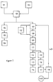
- the normal cycle is defined by the flow chart in Figure 2.
- the cycle will begin with the insertion either of coins (101) or of a magnetic card (102), followed by validation (103) by the electronic system.
- the cup dispensing system (104) will be activated, which will activate the cup placement sensor )105), which will allow the sugar sachet and spoon dispenser mechanism (106) to be activated.
- the motor will be started to move the axle of the six-orifice drum of the citric unit dispenser (107), detecting the passage of the citric unit and inserting the citric unit into the extracting device (109). Should the sensor not detect the passage of the citric unit as it passes (108), the cylinder will be driven again, being allowed to rotate 120 degrees.
- step (109), of inserting the citric unit into the juice extracting device the activation signal will be given to the ram (111), to subsequently give the signal to cut and squeeze the citric unit (112).
- the liquid obtained shall be pumped (113), coming out finally at the external output and falling into the cup (114).
- step (112) the reverse steps will be applied in the extracting mechanisms to prepare the said device for the next extraction, drawing back the retention piston (115), dropping the citric remains into their container (116) and placing the pistons in their initial position (117).
- step (118) will cause the sequence to be repeated from step (107), ending (118) the cycle following the third repetition (119).
- the system After a certain time passes without extraction or after a certain number of extraction cycles, the system will automatically activate a cleaning cycle as shown in Figure 3.
- the start is caused by a signal (201) coming from the control electronics, after which the three-way valve will be switched and water will be transferred from the water container (202), being sucked into the water pump (203), which will pass it to the jets situated in the juice extracting device (204), at the same time opening the pistons and allowing the water to pass through the pump and the juice pipes or channels (205), ending up finally in a container for water and citric remains (206), stopping the pump (207), and switching back the three-way valve.
- FIGS 5 and 6 show the dispenser device (5) which will select each of the tubes (42) of the citric unit frame or store.
- the rotating PVC band (50) can be seen as a blind tensed over some rollers (55) which aid its mobility.
- the rotating band (50) is responsible for selecting the dropping of citric units one by one through alternate gaps (51) planned on its surface, thus selecting one of the three tubes (42) which exist in each line of the citric unit store (4).
- a rotating cylinder has been provided (52), equipped with gaps (56), which will be moved through guide-rails (53) planned to run along the supports (54) situated on either side, achieving the fall of a citric unit from the store to the juice extracting module when the two holes (56) and (51) coincide.
- the disposition of the dispensing device towards the citric unit tube selection (42) may be recognized, being of a matrical nature; i.e. a row with citric units is selected to then select a column.
- the piston (71) will draw back, opening behind it an orifice (73) in the base through which the waste will be disposed of by a thrust of the piston (64), this waste falling the a rear waste hopper, defined above.
- the treatment line for citric units which enter via an intake hopper (4a), falling from the different tuber (42) arrayed in the store (4).
- the dispenser (5) Surrounding the said store (4) is the dispenser (5), equipped with its rotating band (50) supported on rollers (55) and the intake cylinder (52), which, upon selecting a citrus units, will drop it through and discharge hopper (5a) to fall into the juice extracting device (6), where the liquid will pass to the pump (7a) which will drive it out and where the waste will fall into the hopper (9), beside the liquid hopper (10c).
Abstract
Self-contained automatic citric juice extracting and dispensing machine of the type of public service machines dispensing consumable liquid and solid products, based on an electronic circuit with microprocessor which controls a series of devices which provide for the sorting and dosing of citric units (5) so that, when reaching an internal squeezer (6), said citric units are mechanically cut and squeezed and, as a result, the amount or dose previously selected by the users, is received in a cup provided by the machine, said machine providing internally both for the expulsion of residues and waste and for the internal cleaning and washing of the parts soiled by the extracting operation or the passage of the juice.
Description
- This invention deals with presenting a citric juice extracting system within the framework of a public dispensing machine.
- It is well-known that there exist citric juice extractors wit electric-electronic control, ever since the appearance of the first domestic robots of small size which gave an axis the necessary rotational force to rub against the inside of the citric fruit, situated over the axis of a body which dealt with pressing and dragging as it turned the inside of the citric fruit which was held firm over the said body, straining the juice produced by the said action through the base of the said juice extracting unit. This mechanism was controlled by pushing a button, later evolving to a system where it was only necessary to press the citrus fruit vertically upon the revolving extracting body, which had two stable positions, and upper, stop, position, and a lower one driving the axis.
- This type of domestic robot, had their parallel in industrial citric juice extracting machines, with subsequent packing for distribution and sales.
- Alongside certain dispensing mechanisms for edible liquids or solids, such as coffee, confectionary, etc. juice dispensers appeared, which contained the product to be served in reserves inside the machine, which, by means of an electronic selection system combined, for example in the case of coffee machines, a mix of suitable proportions for the selection of the liquid coffee and the milk contained in its stores. The same happened with the juice dispensing machines, in which the juice of various fruits was stored pre-pressed, in respective stores or containers, pouring the liquid into a cup, after selection.
- The problem of the aforementioned dispensing machines lay in the number of times the machine was under-used, which meant the liquid or juice lay stagnant for a long time, which caused a gradual deterioration of the product, at times even reaching the point of being unfit for consumption.
- This problems is one of those which has led to the creation and invention of the machine subject of this report. In the machine of this invention the risk described above has been removed by incorporating a citric unit storage device and subsequent extraction mechanism for the fruit, so that at all times fresh citric juice is obtained, in the knowledge that juice contained in citric fruit keeps longer than once extracted. In the machine of this invention citric fruit, preferably of diameters between 86 and 80 millimetres may be stored; approximately 384 pieces of fruit may be stored, while all the interior devices are fitted inside an external casing of similar dimensions to coffee or canned soft drink dispensers.
- To better understand the subject of this invention, a practical model of the invention has been proposed in the annexed drawings. In the said drawings:
- Figure 1 is a block diagram containing the mechanisms which form the machine of the invention.
- Figure 2 is a flow chart referring to the sequence of operation of the machine of the invention.
- Figure 3 is a flow chart of the internal cleaning process of the machine.
- Figure 4 is a cross-section of the citric fruit store.
- Figure 5 is a front view of the dispensing device of the machine subject of this invention.
- Figure 6 is a side view of the machine subject of this invention.
- Figure 7 is a half-section plan view of the juice extracting device in the framework of the machine subject of this invention.
- Figure 8 is a front half-section view of the juice extracting device in the framework of the machine subject of this invention.
- Figure 9 is a front view of the interior of the casing which covers the devices of the machine subject of this inventions, having placed these devices in their permanent locations.
- As illustrated in Figure 1, the machine consists of a series of modules which, once assembled, allow, by the insertion of coins for its operation, having placed pieces of citric fruit in the corresponding internal stores, a cup of citric juice to be obtained from the machine.
- In the said Figure 1, the module identified as (1) will be the money mechanism, which (1) allows the possibility of using the machine subject of this invention either by inserting coins into the device (1a) or by inserting the user's credit card into the device (1b). The acceptance of coins or credit cards will be supervised by an electronic controller (3), which, like the rest of the control devices, will consist of a PC-type computer, to be described below. The said electronic controller (3) will also control the electronic supply equipment which will supply the various devices contained within the system. The modules described up to now, form the control part of the system; we now move on to describe the physically operating modules which directly influence the result of the machine.
- Thus, there is a first, citric unit container module (4), which consists of a frame (41) of stainless steel with finishing surface treatment and plastic finishing, which bear an alternating grid of 48 tubes (42) manufactured in PVC, preferable of a diameter of 90 millimetres, with a preferable length of 640 millimetres, as can be seen in Figure 4.
The tubes are fixed together with contact adhesive (43), which avoids any relative displacement between them. - Next, the module (5), or citric unit dispenser, has been located in the machine, the contents of which are explained in greater detail in Figures 5 and 6; this consists of two bands of reinforced PVC, the preferable dimensions of which are 800 millimetres by 500 millimetres, 90 millimetres apart, which are fastened to a toothed band which is moved by a geared motor unit, or a continuous or step-by-step motor, shuttling between the two longitudinal sides of the storage unit (4). Between the two bands, a rotor with six cavities is housed, where the citric fruits will be placed one by one as the said cavities match up with the citric unit storage tubes (42). Thus, the citric fruit contained in the tubes (42) of the store (4) will be steadily distributed, one by one, to the juice extracting module (6).
- The juice extracting device (6) consists of a tube down which the citric fruit runs from the feeder (5) to the top of the aforesaid juice extracting device (6), consisting of a tube, of a lesser diameter than the first, through which move two pistons and the citric unit-cutting blades.
- Parallel to the juice extracting device (6), the system has been equipped with a cleaning device (8) for the juice extracting device (6), which, via an orifice opened in the extracting system, injects water under pressure for the periodic cleaning of the compression chamber, this cleaning cycle being self-contained and depending upon the use of the juice extracting device (6). When the cleaning cycle begins, water will be pumped, cleaning the chamber, pipes and pump through which the juice runs, ending up in a three-way valve close to the juice outlet of the machine, which will divert the flow to an unloading tank.
- Once the citric units have been squeezed, the juice passes to a hopper. Once finished, it is pumped to a cup situated in the machine and accessible from outside. Thus, the juice passes to the receiving hopper of the juice pumping unit (7) which will deliver the juice via the juice container (10b) of the refrigeration chamber (10) to a cup situated outside the machine, using to this end the suction and driving pipes of the product, a peristaltic pump and a three-way electrically operated valve, being assisted externally by an air compressor (9) for sucking and driving the liquid.
- The refrigeration chamber (10), moreover, will contain two more containers deployed to accept on the one hand citric remains (10c) and on the other, water (10c).
- In parallel, the system provides cups and sugar contained in sachets, stored respectively in (11) and (13), which are ejected via the dispenser modules (12) and (14) respectively. The means of ejection in both dispensers is based in a ramming mechanism consisting of either a rack and pinion geared motor outfit or an hydraulic micro-cylinder.
- The operation of the machine has been summarised in a flow chart like that described in Figure 2 referring to the basic working of the electronic circuits forming the system. To realize the said controls the system will be equipped with a series of magneto-thermal protectors, for differential or earth leaks and for over-voltage; the AC grid will supply the different pieces of powered equipment, either in AC or in direct current for motors, pumps, etc., as well as the electronic circuits via a switching supply. The drive power of the equipment will be supplied through relays and contactors, controlled by the electronic component.
- The drives of the system, which will be controlled from the electronic component, will be: the air compressor, the refrigerator cabinet, the cabinet lighting, the electrically operated valves of the squeezing pistons, the citric unit collection motors in the feeder, the cleaning pump for the juice extracting device and its piping, the electrically operated valve which will distinguish the cleaning cycle from the normal operating cycle, the sugar dispenser, the cup dispenser, the magnetic card reader, the coin collector, a selection and error indicator display, a modem or data terminal attached to the magnetic card reader, a detector of liquid output from the machine and a cup placement sensor. The electronic control component will be based on an industrial PC-type computer, which will consist of an industrial microprocessor at 31 megahertz speed, with 512 kilobytes of random access memory, a virtual disk with dual ROM and RAM program with battery, a real-time clock with battery, to RS-232 series ports, two parallel ports, two cards with eight opto-isolated digital inputs and eight digital outputs and watchdog circuit to restart the system in the case of serious failure.
- The software with which the control electronics have been equipped is planned to distinguish two parallel processes, namely that of external of physical action, in the normal juice extracting cycle, and the machine's internal cleaning cycle.
- The normal cycle is defined by the flow chart in Figure 2. The cycle will begin with the insertion either of coins (101) or of a magnetic card (102), followed by validation (103) by the electronic system. Following validation (103), the cup dispensing system (104) will be activated, which will activate the cup placement sensor )105), which will allow the sugar sachet and spoon dispenser mechanism (106) to be activated. Alongside these steps (104), (105) and (106), the motor will be started to move the axle of the six-orifice drum of the citric unit dispenser (107), detecting the passage of the citric unit and inserting the citric unit into the extracting device (109). Should the sensor not detect the passage of the citric unit as it passes (108), the cylinder will be driven again, being allowed to rotate 120 degrees. If the response is still negative, the action will be repeated again. If, even so, there is still no affirmative signal of the passage of citric unit a new motor will be activated (110) to permit the drum or cup set to be moved forward to a spot where the citric unit store has stock to load the aforementioned dispenser drum or cup.
- Once step (109), of inserting the citric unit into the juice extracting device, is reached, the activation signal will be given to the ram (111), to subsequently give the signal to cut and squeeze the citric unit (112). The liquid obtained shall be pumped (113), coming out finally at the external output and falling into the cup (114).
- Alongside step (112), the reverse steps will be applied in the extracting mechanisms to prepare the said device for the next extraction, drawing back the retention piston (115), dropping the citric remains into their container (116) and placing the pistons in their initial position (117). Given that it is planned for the extraction of three citric units to be the equivalent of one cup of juice, step (118) will cause the sequence to be repeated from step (107), ending (118) the cycle following the third repetition (119).
- After a certain time passes without extraction or after a certain number of extraction cycles, the system will automatically activate a cleaning cycle as shown in Figure 3. In this cycle, the start is caused by a signal (201) coming from the control electronics, after which the three-way valve will be switched and water will be transferred from the water container (202), being sucked into the water pump (203), which will pass it to the jets situated in the juice extracting device (204), at the same time opening the pistons and allowing the water to pass through the pump and the juice pipes or channels (205), ending up finally in a container for water and citric remains (206), stopping the pump (207), and switching back the three-way valve.
- To describe in greater detail the physical equipment specified up to now, Figures 5 and 6, which define the dispensing device, and Figures 7 and 8, which define the juice extracting device, as well as a general interior view in Figure 9 in order to observe an aspect of practical performance.
- Figures 5 and 6 show the dispenser device (5) which will select each of the tubes (42) of the citric unit frame or store. In the said Figures the rotating PVC band (50) can be seen as a blind tensed over some rollers (55) which aid its mobility. The rotating band (50) is responsible for selecting the dropping of citric units one by one through alternate gaps (51) planned on its surface, thus selecting one of the three tubes (42) which exist in each line of the citric unit store (4). To select the rows of citric units, a rotating cylinder has been provided (52), equipped with gaps (56), which will be moved through guide-rails (53) planned to run along the supports (54) situated on either side, achieving the fall of a citric unit from the store to the juice extracting module when the two holes (56) and (51) coincide. Thus, the disposition of the dispensing device towards the citric unit tube selection (42) may be recognized, being of a matrical nature; i.e. a row with citric units is selected to then select a column. This characteristic allows the number of citric units which have been consumed in any given moment to be known, knowing the movements made both by the motors of the rotating band (59) from one position to another, and knowing the movements made by the motor in charge of moving the cylinder (52), as both (50) and (52) are the means of dispensing citric units.
- In Figures 7 and 8, two views of the juice extracting device (6) have been displayed. In both Figures the citric unit intake opening (60), circular in section, can be seen. The citric unit, falling through the dispenser (4) will enter by the intake opening (60) and fall into the chamber (61).
- In the middle area of the chamber (61) cutting blades (62) have been arrayed. To place the citric unit, next to the area where the cutting blades (62) are situated, a piston (64) has been fitted, with a frontal aspect such that, as it reaches along the chamber (61) opposite the blades (62), they fit into slots (65) so that it can thus pass over the obstacle presented by the blades (62) and they can cut the orange with the drive of the piston.
- In Figure 8, two cylinders (66) may be observed, the shafts of which (67) connect solidly with the piston (64), via the connection points (68a and 68b). From the extension of the shaft (67) of the cylinder (66), the piston (64) will be driven closer down the length of the chamber, thus pushing the citric unit towards the blades (62) where, once over the obstacle, with the citric unit now cut, the cylinder (69) situated on the longitudinally opposite position to the piston (64) will extend, the shaft (70) of said cylinder (69) being responsible for driving, via its solid piece (71), the opposite end of the piece of the citric unit, so that under the pressure upon the piece of citric unit by the two pistons (64) and (71) and extraction of citric juice is produced; the said juice will fall through orifices (72) in the base of the chamber (61), which via an channel outside the said juice extracting device (6), carry the juice to the outlet nozzle.
- Once the piece of citric unit has had its juice extracted, the piston (71) will draw back, opening behind it an orifice (73) in the base through which the waste will be disposed of by a thrust of the piston (64), this waste falling the a rear waste hopper, defined above.
- To provide all the devices with an appearance of unity, as well as a design to present the machine to the public, it has been laid out as in Figure 9. In the said Figures the prismatic appearance of the machine of the invention can be observed, in which the upper area is occupied by the refrigeration chamber (10) equipped with a refrigeration compressor (10d). Beside them is the air compressor (9), principally for the aspiration and driving of liquids.
- On a lower level lies the treatment line for citric units, which enter via an intake hopper (4a), falling from the different tuber (42) arrayed in the store (4). Surrounding the said store (4) is the dispenser (5), equipped with its rotating band (50) supported on rollers (55) and the intake cylinder (52), which, upon selecting a citrus units, will drop it through and discharge hopper (5a) to fall into the juice extracting device (6), where the liquid will pass to the pump (7a) which will drive it out and where the waste will fall into the hopper (9), beside the liquid hopper (10c).
- Having sufficiently described the nature of this invention, as well as a way of putting it into practice, all that remains to be done is to add that, as a whole and in its components, it is possible to introduce changes of materials, as long as they do not substantially alter the characteristics claimed below.
Claims (6)
- Self contained automatic citric juice extracting and dispensing machine, of the type of drink and solid food public vending machines, characterised by being composed of a series of devices which manage to offer the user freshly squeezed juice, said devices being a citric unit store where the citric units are placed, a device to dispense a certain number of units per selection from the citric unit store, a citric juice extracting device which is fed with citric units by the dispenser. a fluid pump fitted into the outlet of the juice extracting device, responsible for supplying the juice obtained by extraction to the outlet where a cup has been placed, where the aforementioned juice will fall, disposing in turn of the remains of the citric units, from the juice extracting device, to the hopper intended to collect the waste, it being possible to clean the chambers and piping when they are dirtied by extracting operations, complementarily to the operation of the juice extracting operation of the machine, there being electronic control based upon a microprocessor system using software, responsible for controlling and ordering the operation of the devices in the order explained above and issuing, when there is no operation in normal mode, the necessary signals to execute the cleaning action.
- Self contained automatic citric juice extracting and dispensing machine, as per the first claim, characterised because the citric unit store is composed of a metal frame which supports a lattice of tubes, the preferable number of which is 48 units, laid out in files and columns in staggered or alternate form, there being inside each tube a given number of citric units, the tubes being in contact with each other and being held together by the action of a given glue or contact adhesive, thus forming a compact block.
- Self contained automatic citric juice extracting and dispensing machine, as per the first claim, characterised because the dispenser device is equipped with an endless, flat PVC band, rotating thanks to the action of a motor, whether continuous or step by step, which in its lower lengthwise stretch is in contact with the storage tubes, having drilled holes in its surface which will allows citric units to pass from the storage tubes, which will pass through the device to a discharge hopper, when it matches up with the holes in a cylinder with horizontal generants which places itself below a row of tubes, thanks to the action of a motor which moves it both rotationally and longitudinally along guide-rails which support its axial ends, the selection of a given citric units then being the consequence of the matching up of both holes, which, between the two, select a row and a tube of the said row, the citric unit falling through a discharge hopper which places it in the juice extracting device.
- Self contained automatic citric juice extracting and dispensing machine, as per the first claim, characterised because the juice extracting device consists of a vertical intake, through which a citric unit coming from the citric unit dispensing device enters into a chamber, being pushed by the action of a lengthwise running piston, driven by two laterally situated cylinders, the shafts of which connect solidly with the said piston, the piston pushing the citric unit piece, as the respective cylinders extend simultaneously their respective shafts, towards a central area where blades block the way and cut the piece of citric fruit as it is pushed by the piston, which has slots in its face to ensure the complete section of the citric unit, activating at the same time a second cylinder situated at the top of the chamber, which, as it extends its shaft will move a second piston in the part of the chamber opposite the first, pressing the cut piece of citric fruit by the action of compression of both pistons, the juice finally falling through orifices situated in the top part of the chamber, at the height of the blades, the shaft of the second cylinder subsequently withdrawing so as to leave free a lower orifice for the removal of remains and waste, a removal which is carried out by an additional extension of the shaft of the first cylinder which involves an extended travel of the first piston, which will push the remains of the citric unit into the waste disposal orifice.
- Self contained automatic citric juice extracting and dispensing machine, as per the first and fourth claims, characterised because the cleaning cycle will be performed when there is no order for selection and juice extraction of citric units, this being performed in the chamber of the juice extracting device by means of the injection of water, which will clean both the said camera and the front surface of the pistons, the juice outlet orifices, the way through the juice service pump and the respective piping, the water being channelled to an exterior tank thanks to the switching of an three-way electrically operated valve situated a few centimetres before the juice outlet from the machine, specifically to the cup.
- Self contained automatic citric juice extracting and dispensing machine, as per the first claim, characterised because a refrigeration chamber has been situated inside, placed as a module before the juice outlet from the machine.
Applications Claiming Priority (1)
| Application Number | Priority Date | Filing Date | Title |
|---|---|---|---|
| PCT/ES1994/000083 WO1996006541A1 (en) | 1994-09-01 | 1994-09-01 | Self-contained automatic citric juice extracting and dispensing machine |
Publications (1)
| Publication Number | Publication Date |
|---|---|
| EP0728422A1 true EP0728422A1 (en) | 1996-08-28 |
Family
ID=8284945
Family Applications (1)
| Application Number | Title | Priority Date | Filing Date |
|---|---|---|---|
| EP94925489A Ceased EP0728422A1 (en) | 1994-09-01 | 1994-09-01 | Self-contained automatic citric juice extracting and dispensing machine |
Country Status (5)
| Country | Link |
|---|---|
| US (1) | US5671663A (en) |
| EP (1) | EP0728422A1 (en) |
| JP (1) | JPH09506265A (en) |
| AU (1) | AU7537894A (en) |
| WO (1) | WO1996006541A1 (en) |
Cited By (2)
| Publication number | Priority date | Publication date | Assignee | Title |
|---|---|---|---|---|
| WO2000057731A1 (en) * | 1999-03-30 | 2000-10-05 | Baskaeva, Fatima Amurbievna | Device for preparing juice and distributing it into portions |
| WO2002096226A1 (en) * | 2001-05-31 | 2002-12-05 | Zumomatic España, S.L. | Improvements to citrus fruit-squeezing machines |
Families Citing this family (9)
| Publication number | Priority date | Publication date | Assignee | Title |
|---|---|---|---|---|
| ES2130077B1 (en) * | 1997-06-26 | 2000-01-16 | Catarain Arregui Esteban | AUTOMATIC NATURAL JUICE SUPPLY MACHINE. |
| US20050058755A1 (en) * | 2003-09-17 | 2005-03-17 | Burgess Chambers | Relocatable processing plant for extracting juice from citrus fruit and associated methods |
| ES2284294B1 (en) * | 2003-10-31 | 2009-04-16 | Zumex, Maquinas Y Elementos, S.A. | EXPRESSING MACHINE FOR REDUCED SIZE CITRIC FRUITS. |
| KR100745196B1 (en) * | 2006-07-19 | 2007-08-01 | 이창석 | Vending machine for fruit juice and controlling method thereof |
| GB2454674A (en) * | 2007-11-14 | 2009-05-20 | Dyson Technology Ltd | Domestic Appliance |
| JP2013126375A (en) * | 2010-04-02 | 2013-06-27 | Bio Chromato Co Ltd | Juice extractor and juice extraction method |
| US9155330B1 (en) * | 2014-11-01 | 2015-10-13 | Aleksey Shtivelman | Automated vending machine for producing beverages using comestibles |
| US20180330566A1 (en) * | 2017-05-15 | 2018-11-15 | RobotsFoods Corporation | Automated vending machines for making juice products and cotton candy |
| CN107244088B (en) * | 2017-08-14 | 2019-02-19 | 安徽香杨新能源科技发展有限公司 | A kind of novel pueraria lobata draining device |
Family Cites Families (11)
| Publication number | Priority date | Publication date | Assignee | Title |
|---|---|---|---|---|
| US3086455A (en) * | 1958-11-17 | 1963-04-23 | Fmc Corp | Fruit processing apparatus |
| EP0110947A1 (en) * | 1982-06-08 | 1984-06-20 | Sutcliffe Catering Group Limited | Vending machines |
| US4706793A (en) * | 1985-07-15 | 1987-11-17 | Camillo Masciarelli | Conveyor system with rollers and plungers |
| IT1220378B (en) * | 1988-05-24 | 1990-06-15 | Aid Agricolture Ind Dev | AUTOMATIC CITRUS JUICE DISTRIBUTOR |
| US4951563A (en) * | 1988-09-06 | 1990-08-28 | Warren Loyd C | Fully automatic citrus fruit juice extractor |
| US4922814A (en) * | 1988-09-12 | 1990-05-08 | Anderson David N | Single head juice extractor |
| US4917007A (en) * | 1989-09-06 | 1990-04-17 | The Automatic Orange Juicer Corporation | Juicing apparatus |
| ES2037576B1 (en) * | 1991-03-15 | 1994-01-16 | Instazum S L | MACHINE FOR THE INSTANT PREPARATION OF FRUIT JUICES. |
| US5182984A (en) * | 1991-09-16 | 1993-02-02 | Hollymatic Corporation | Automated citrus fruit juice press |
| US5445068A (en) * | 1994-06-02 | 1995-08-29 | Michelson; Yigal | Apparatus and method for extracting juide from citrus fruits |
| US5483870A (en) * | 1995-05-12 | 1996-01-16 | Anderson; David N. | Countertop citrus juicer |
-
1994
- 1994-09-01 AU AU75378/94A patent/AU7537894A/en not_active Abandoned
- 1994-09-01 JP JP8508502A patent/JPH09506265A/en active Pending
- 1994-09-01 EP EP94925489A patent/EP0728422A1/en not_active Ceased
- 1994-09-01 WO PCT/ES1994/000083 patent/WO1996006541A1/en not_active Application Discontinuation
- 1994-09-01 US US08/605,220 patent/US5671663A/en not_active Expired - Fee Related
Non-Patent Citations (1)
| Title |
|---|
| See references of WO9606541A1 * |
Cited By (2)
| Publication number | Priority date | Publication date | Assignee | Title |
|---|---|---|---|---|
| WO2000057731A1 (en) * | 1999-03-30 | 2000-10-05 | Baskaeva, Fatima Amurbievna | Device for preparing juice and distributing it into portions |
| WO2002096226A1 (en) * | 2001-05-31 | 2002-12-05 | Zumomatic España, S.L. | Improvements to citrus fruit-squeezing machines |
Also Published As
| Publication number | Publication date |
|---|---|
| AU7537894A (en) | 1996-03-22 |
| US5671663A (en) | 1997-09-30 |
| JPH09506265A (en) | 1997-06-24 |
| WO1996006541A1 (en) | 1996-03-07 |
Similar Documents
| Publication | Publication Date | Title |
|---|---|---|
| US7475628B2 (en) | Device for dispensing milk and/or milk froth | |
| US5671663A (en) | Self-contained automatic citric juice extracting and dispensing | |
| US6234071B1 (en) | Automatic machine for dispensing natural juices | |
| US4974505A (en) | Fruit juice automatic dispenser | |
| JP5503715B2 (en) | Beverage machine drain | |
| DK2592953T3 (en) | Automatic distributor for juices which are produced from fresh fruit | |
| KR101418505B1 (en) | Coffee vending machine | |
| OA12261A (en) | Device for extraction a substance. | |
| US20170039797A1 (en) | Smoothie Delivery Vending System | |
| EP2024944A2 (en) | Vending apparatus for dispensing drinks that contain fruits or vegetables | |
| US3203340A (en) | Beverage brewing and dispensing mechanism | |
| CA2971809A1 (en) | Beverage vending machine | |
| US10098492B2 (en) | Juicing device for agricultural products such as citrus fruits and the like | |
| KR200441803Y1 (en) | A Manufacturing apparatus for fruit juice | |
| US3089404A (en) | Automatic coffee machine | |
| US8733121B2 (en) | Snow cone and slushy dispenser | |
| US3152728A (en) | Drink dispenser with metering syringe and reconstituting nozzles | |
| US2817935A (en) | Fruit juice machine | |
| US5680809A (en) | Device for brewing coffee, tea or similar drinks | |
| JP2949693B2 (en) | Fully automatic pack extraction machine | |
| CN209842776U (en) | Automatic vending machine | |
| WO2020217257A1 (en) | A device for dispensing tender coconut water and method thereof | |
| US1478224A (en) | Fruit-juice machine | |
| JPH0927078A (en) | Pack type drink supply device equipped with ice making machine | |
| CN108648347B (en) | Automatic breakfast retail machine |
Legal Events
| Date | Code | Title | Description |
|---|---|---|---|
| PUAI | Public reference made under article 153(3) epc to a published international application that has entered the european phase |
Free format text: ORIGINAL CODE: 0009012 |
|
| AK | Designated contracting states |
Kind code of ref document: A1 Designated state(s): AT BE CH DE DK ES FR GB GR IE IT LI LU MC NL PT SE |
|
| 17P | Request for examination filed |
Effective date: 19961113 |
|
| 17Q | First examination report despatched |
Effective date: 19990924 |
|
| STAA | Information on the status of an ep patent application or granted ep patent |
Free format text: STATUS: THE APPLICATION HAS BEEN REFUSED |
|
| 18R | Application refused |
Effective date: 20020722 |