EP0727864A2 - Electric motor interconnection board - Google Patents
Electric motor interconnection board Download PDFInfo
- Publication number
- EP0727864A2 EP0727864A2 EP96100710A EP96100710A EP0727864A2 EP 0727864 A2 EP0727864 A2 EP 0727864A2 EP 96100710 A EP96100710 A EP 96100710A EP 96100710 A EP96100710 A EP 96100710A EP 0727864 A2 EP0727864 A2 EP 0727864A2
- Authority
- EP
- European Patent Office
- Prior art keywords
- circuit arrangement
- base part
- receptacle
- connector
- arrangement according
- Prior art date
- Legal status (The legal status is an assumption and is not a legal conclusion. Google has not performed a legal analysis and makes no representation as to the accuracy of the status listed.)
- Granted
Links
Images


Classifications
-
- H—ELECTRICITY
- H02—GENERATION; CONVERSION OR DISTRIBUTION OF ELECTRIC POWER
- H02K—DYNAMO-ELECTRIC MACHINES
- H02K3/00—Details of windings
- H02K3/46—Fastening of windings on the stator or rotor structure
- H02K3/50—Fastening of winding heads, equalising connectors, or connections thereto
-
- H—ELECTRICITY
- H02—GENERATION; CONVERSION OR DISTRIBUTION OF ELECTRIC POWER
- H02K—DYNAMO-ELECTRIC MACHINES
- H02K11/00—Structural association of dynamo-electric machines with electric components or with devices for shielding, monitoring or protection
- H02K11/20—Structural association of dynamo-electric machines with electric components or with devices for shielding, monitoring or protection for measuring, monitoring, testing, protecting or switching
- H02K11/25—Devices for sensing temperature, or actuated thereby
-
- H—ELECTRICITY
- H02—GENERATION; CONVERSION OR DISTRIBUTION OF ELECTRIC POWER
- H02K—DYNAMO-ELECTRIC MACHINES
- H02K2203/00—Specific aspects not provided for in the other groups of this subclass relating to the windings
- H02K2203/03—Machines characterised by the wiring boards, i.e. printed circuit boards or similar structures for connecting the winding terminations
Definitions
- the present invention relates to an interconnection arrangement for connecting wire ends of a stator winding of an electric motor, in particular an external rotor motor, to connection conductors, with a base part made of electrically insulating material, in particular disk-shaped base part, and with electrical connector elements held on the base part for connecting the wire ends or the connection leads as well as with a holder for a temperature monitor.
- Such an interconnection arrangement is known from DE 42 43 845 A1. It consists of an interconnection plate, which is fastened to an end insulation shaft of the stator with a receiving opening, and of connecting elements, on the one hand, connector sections arranged in pocket-shaped recesses of the interconnection plate for the connection conductors of a motor connection cable and on the other hand have connection lugs for the electrical connection of the winding wire ends.
- the connecting elements are designed as stamped sheet metal parts which have holes for holding on the circuit board, which are penetrated by pin-like elevations of the circuit board. The connecting elements are held (“caulked") by means of the elevations by the action of heat and the application of a pressure to the interconnection plate.
- the known circuit board also has a hollow cylindrical approach, which forms a receptacle for inserting a temperature monitor.
- a temperature monitor is used within electric motors to switch off the motor current in the event of overheating.
- the temperature monitor is in heat-conducting contact with the stator winding and is electrically connected in series with the stator winding; it interrupts the connection if a certain switch-off temperature is exceeded.
- the motor protection can be taken over by an external fuse that is already present in the customer device.
- the temperature monitor inside the motor can be omitted and the motor can be produced more cheaply.
- the present invention is therefore based on the object of creating an interconnection arrangement of the generic type which, with basically the same basic concept, is suitable both for motors with a temperature monitor and for less expensive motors without a temperature monitor, so that the production and storage of the corresponding electric motors is particularly good Economy is achieved.
- a first connector element has a contact spring element which is electrically conductively connected to a mating contact surface of a second connector element in the region of the receptacle for the temperature monitor.
- a version with a temperature monitor or a version without a temperature monitor can be implemented very easily, because, due to the contact spring element of the first connector element according to the invention, which is arranged in the area of the temperature monitor receptacle, and because of the mating contact surface of the second connector element, either between these elements can be used within a temperature monitor can be arranged in the receptacle (indirect electrical connection of the contact spring element to the counter-contact surface), or these elements can contact one another directly without an intermediate arrangement of a temperature monitor. Based on the same basic concept, the invention can thus be used to produce motors either with a temperature monitor or without a temperature monitor. Overall, this leads to particularly good economy, since the Temperature monitors can be saved without a special motor design being required.
- the second connector element is provided in two slightly different embodiments.
- the second connector element has a contact section forming the counter-contact surface, which is supported on the opening side of the receptacle facing the contact spring element on a support step formed there against a pressing force caused by the contact spring element.
- the contact section practically forms a kind of "cover", which closes the receptacle, which remains free or remains empty without a temperature monitor.
- the counter-contact surface lies at least approximately in the plane in which a contact surface of a temperature monitor located in the receptacle would also be arranged.
- the second connector element in its second embodiment has a contact section which has or forms the counter-contact surface and is arranged within the receptacle on the side of the temperature monitor facing away from the contact spring element, for example lying on a bottom wall.
- This contact section thus has a smaller surface area than that of the first embodiment, wherein it is cranked downward into the receptacle relative to the remaining part of the second connector element.
- an interconnection arrangement 1 is used to connect or interconnect wire ends 2 of a stator winding 4 (cf. FIG. 12), in particular an electric external rotor motor with connecting conductors 6 of a motor connection cable 8.
- a stator winding 4 cf. FIG. 12
- an electric external rotor motor with connecting conductors 6 of a motor connection cable 8.
- an interconnection arrangement for this 1 essentially consists of a preferably annular disk-shaped base part 10 and electrical connector elements 12 held thereon or to which the wire ends 2 and / or the connecting conductors 6 can be electrically connected.
- the base part 10 consists of an electrically insulating material, suitably plastic, and has a preferably approximately central opening 14 with which the base part 10 - see FIG. 12 - can be fastened on a front insulation shaft 16 of the motor or stator in such a way that the disc-shaped base part 10 also functions as a winding head cover.
- a receptacle 18 for a temperature monitor 20 is also provided.
- a temperature monitor 20 is preferably used, which is essentially designed as a flat, cylindrical body.
- the receptacle 18 has a corresponding inner contour with a flat, cylindrical shape. This can best be seen in FIGS. 3 and 4.
- the receptacle 18 is expediently formed by a corresponding spatial shape of the base part 10, which is preferably designed as a one-piece plastic molded part.
- the connector elements 12 held on the base part 10 now include a first connector element 22 and a second connector element 24, the second Connector member 24 is preferably present in two slightly different embodiments; 7 to 11, these slightly different connector elements are provided with the reference numerals 24a and 24b.
- the first connector element 22 now has a contact spring element 26, which is connected in an electrically conductive manner in the area of the receptacle 18 for the temperature monitor 20 to a counter-contact surface 28 of the second connector element 24. According to the invention, it is therefore possible to optionally provide a version with or without a temperature monitor. This will now be explained in more detail with reference to FIGS. 7 to 11.
- FIGS. 10 and 11 An embodiment without a temperature monitor is illustrated in FIGS. 10 and 11.
- the first connector element 22 is connected to the second connector element 24a directly by direct contact of the contact spring element 26 on the mating contact surface - here designated 28a.
- the second connector element 24a is preferably provided with a contact section 30a having the counter-contact surface 28a on the opening side of the receptacle 18 facing the contact spring element 26 on a preferably annular support step 32 (see in particular FIGS. 3 and 4) against one of the contact spring element 26 caused pressure force F supported.
- the contact section 30a thus practically forms a type of cover for the receptacle 18 which remains empty in this motor design. This can be seen clearly in FIGS. 10 and 11.
- the first connector element 22 is indirectly above that arranged in the receptacle 18
- Temperature monitor 20 is connected to the second connector element 24b, the temperature monitor 20 being arranged between the contact spring element 26 and the mating contact surface 28b each with an electrical contact.
- the contact spring element 26 rests on the temperature monitor 20 with the contact pressure F.
- the second connector element 24b is arranged with a contact section 30b having the counter-contact surface 28b within the receptacle 18 on the side of the temperature monitor 20 facing away from the contact spring element 26. For this reason, as can be seen from FIG.
- the contact section 30b is smaller in terms of its area size than the contact section 30a of the other embodiment of the second connector element 24a.
- the contact section 30b can be inserted into the receptacle 18 instead of lying on the support step 32.
- the contact section 30b expediently rests on a bottom wall 34 of the base part 10 which delimits the receptacle. It is advantageous if a hole opening 36 is formed in this bottom wall 34 such that in the state of the base part 10 connected to the stator - see FIG.
- the temperature monitor 20 arranged in the receptacle 18 through the hole opening 36 with the heat is applied to the stator winding 4, specifically indirectly via the contact section 30b of the second connector element 24b and, if appropriate, via a circuit insulation 68 Temperature monitor 20 against the force F.
- the connector elements 12 are in the form of stamped sheet metal parts which are arranged essentially flat on the base part in the form of an annular disk are supported.
- the holder is preferably carried out by pin lugs 38 of the base part 10, which are guided through holes 40 of the connector elements 12 to produce positive-locking connections and, in particular, are deformed thermally and mechanically in the manner of a “rivet head” (“calked”).
- the heating can advantageously be carried out using the ultrasound method.
- the pin lugs 38 are shown in their not yet caulked state. 8 and 10, however, the caulked state is also indicated by dots.
- the first connector element 22 has a bridge section 42 covering the area of the temperature monitor receptacle 18, from which the contact spring element 26 is cut free or punched out or punched out and in the direction of the receptacle 18 is bent so that it can contact the temperature monitor 20 or the contact section 30a with its free end and then be applied with the force F.
- the arc shape of the contact spring element 26 can be clearly seen in FIGS. 8 to 11.
- a cover 44 which closes the receptacle 18 and is made of an electrically insulating material, is provided, this cover 44 having a hole opening 46 through which the contact spring element 26 extends.
- the lid 44 is shown separately in FIGS. 5 and 6.
- the bridge section 42 of the first connector element 22 now rests on the cover 44 and is thus cranked upward relative to the rest of the part which rests on the surface of the base part 10.
- the cover 44 and the bridge section 42 are preferably held together on the base part 10 via pin extensions 38. This can be seen in FIGS. 1 and 2.
- a slot-like feed-through opening 48 for the contact section 30a, b of the second connector element 24a, b is formed between the base part 10 and the cover 44 (cf. FIGS. 3, 5, 9 and 11).
- the connector elements 12 also include a third connector element 50 and a fourth connector element 52.
- the first connector element 22, the third connector element 50 and the fourth connector element 52 each have a connection which is in particular designed as a crimping section 54. Furthermore, for connecting the wire ends 2 of the stator winding 4, the second connector element 24a or b, the third connector element 50 and the fourth connector element 52 each have a connecting lug 56, which has at its free end a connection, in particular in the form of a clamping tongue 58, for the electrically conductive connection has the respective wire end 2.
- each terminal lug 56 together with the connected wire end 2 from a part of the respective connector element 12 which, in particular, lies at an angle of approximately 90 ° with the rest of the part of the respective connector element 12 lying essentially parallel on a support plane of the base part 10 - see FIG. 2 - bent into an operating position, which is also essentially on the base part 10 - shown in FIG. 1 - in such a way that the wire end 2 is given a pronounced loosening bow 60 which avoids mechanical tension (FIG. 1).
- the connecting lugs 56 are connected to the remaining part of the connector element 12 via bending lines 62 (shown in broken lines in FIG. 1).
- the wire ends 2 are thus connected in an approximately vertical position from the base part 10 of the terminal lugs 56, ie in the connected position, to the clamping tongues 58 and in particular additionally welded. Now the connecting lugs 56 connected to the wire ends 2 are bent into the plane of the base part 10, whereby the winding wires are mechanically relieved, so that wire breaks due to mechanical vibrations which may occur are advantageously avoided.
- the base part 10 provided with the connector elements 12 is preferably covered with an insulating cover 64, which is in particular in the form of an annular disk with an outer peripheral edge 66 that extends axially in the direction of the base part 10 (see FIG. 12).
- the cover 64 is hereby appropriately, e.g. cohesively attached to the base part 10 and / or to the front insulation shaft 16.
- the invention is not limited to the exemplary embodiments shown and described, but also encompasses all embodiments having the same effect in the sense of the invention. Furthermore, the invention has not yet been limited to the combination of features defined in claim 1, but can also be defined by any other combination of specific features of all the individual features disclosed in total. This means that in principle practically every single feature of claim 1 can be omitted or replaced by at least one single feature disclosed elsewhere in the application. In this respect, claim 1 is only to be understood as a first attempt at formulation for an invention.
Abstract
Description
Die vorliegende Erfindung betrifft eine Verschaltungsanordnung zum Verbinden von Drahtenden einer Statorwicklung eines Elektromotors, insbesondere eines Außenläufermotors, mit Anschlußleitern, mit einem aus elektrisch isolierendem Material bestehenden, insbesondere scheibenförmigen Basisteil und mit an dem Basisteil gehalterten, elektrischen Verbinderelementen zum Anschluß der Drahtenden bzw. der Anschlußleiter sowie mit einer Aufnahme für einen Temperaturwächter.The present invention relates to an interconnection arrangement for connecting wire ends of a stator winding of an electric motor, in particular an external rotor motor, to connection conductors, with a base part made of electrically insulating material, in particular disk-shaped base part, and with electrical connector elements held on the base part for connecting the wire ends or the connection leads as well as with a holder for a temperature monitor.
Eine derartige Verschaltungsanordnung ist aus der DE 42 43 845 A1 bekannt. Sie besteht aus einer Verschaltungsplatte, die mit einer Aufnahmeöffnung auf einem Stirnisolationsschaft des Stators befestigt wird, und aus Verbindungselementen, die einerseits in taschenförmigen Ausnehmungen der Verschaltungsplatte angeordnete Steckverbinderabschnitte für die Anschlußleiter eines Motoranschlußkabels und andererseits Anschlußfahnen für den elektrischen Anschluß der Wicklungsdrahtenden aufweisen. Die Verbindungselemente sind hierbei als Blechstanzteile ausgebildet, die zur Halterung auf der Verschaltungsplatte Löcher aufweisen, die von stiftartigen Erhebungen der Verschaltungsplatte durchgriffen werden. Die Verbindungselemente werden mittels der Erhebungen durch Wärmeeinwirkung und Aufbringen eines Preßdruckes auf der Verschaltungsplatte gehaltert ("verstemmt"). Die bekannte Verschaltungsplatte besitzt ferner einen hohlzylindrischen Ansatz, der eine Aufnahme zum Einsetzen eines Temperaturwächters bildet. Solche Temperaturwächter werden innerhalb von Elektromotoren dazu verwendet, im Falle von Überhitzungen den Motorstrom abzuschalten. Hierzu steht der Temperaturwächter in wärmeleitendem Kontakt mit der Statorwicklung und ist elektrisch in Reihe mit der Statorwicklung geschaltet; er unterbricht die Verbindung im Falle der Überschreitung einer bestimmten Abschalttemperatur.Such an interconnection arrangement is known from DE 42 43 845 A1. It consists of an interconnection plate, which is fastened to an end insulation shaft of the stator with a receiving opening, and of connecting elements, on the one hand, connector sections arranged in pocket-shaped recesses of the interconnection plate for the connection conductors of a motor connection cable and on the other hand have connection lugs for the electrical connection of the winding wire ends. The connecting elements are designed as stamped sheet metal parts which have holes for holding on the circuit board, which are penetrated by pin-like elevations of the circuit board. The connecting elements are held ("caulked") by means of the elevations by the action of heat and the application of a pressure to the interconnection plate. The known circuit board also has a hollow cylindrical approach, which forms a receptacle for inserting a temperature monitor. Such temperature monitors are used within electric motors to switch off the motor current in the event of overheating. For this purpose, the temperature monitor is in heat-conducting contact with the stator winding and is electrically connected in series with the stator winding; it interrupts the connection if a certain switch-off temperature is exceeded.
Bei der bekannten Anordnung sind nun zum Kontaktieren des Temperaturwächters zwei ebenfalls als Blechstanzteile ausgebildete Leiterbahnen vorgesehen, die anderendig mit zwei Verbinderelementen verbunden sind. Aufgrund der Ausbildung dieser Verschaltungsanordnung ist sie ausschließlich für Motoren mit Temperaturwächter geeignet.In the known arrangement, two conductor tracks, which are likewise designed as stamped sheet metal parts and are otherwise connected to two connector elements, are provided for contacting the temperature monitor. Due to the design of this circuit arrangement, it is only suitable for motors with temperature monitors.
In vielen Anwendungsfällen, insbesondere dann, wenn der Motor in ein bestehendes Kundengerät eingebaut werden soll, kann der Motorschutz durch eine extern aufgebaute, im Kundengerät bereits vorhandene Sicherung mit übernommen werden. In diesem Falle kann der Temperaturwächter innerhalb des Motors entfallen und der Motor kann kostengünstiger produziert werden.In many applications, especially when the motor is to be installed in an existing customer device, the motor protection can be taken over by an external fuse that is already present in the customer device. In this case, the temperature monitor inside the motor can be omitted and the motor can be produced more cheaply.
Der vorliegenden Erfindung liegt daher die Aufgabe zugrunde, eine Verschaltungsanordnung der gattungsgemäßen Art zu schaffen, die sich bei grundsätzlich gleicher Grundkonzeption sowohl für Motoren mit Temperaturwächter als auch für preiswertere Motoren ohne Temperaturwächter eignet, so daß bezüglich der Fertigung und Lagerhaltung der entsprechenden Elektromotoren eine besonders gute Wirtschaftlichkeit erreicht wird.The present invention is therefore based on the object of creating an interconnection arrangement of the generic type which, with basically the same basic concept, is suitable both for motors with a temperature monitor and for less expensive motors without a temperature monitor, so that the production and storage of the corresponding electric motors is particularly good Economy is achieved.
Erfindungsgemäß wird dies dadurch erreicht, daß ein erstes Verbinderelement ein Kontaktfederelement aufweist, welches im Bereich der Aufnahme für den Temperaturwächter mit einer Gegenkontaktfläche eines zweiten Verbinderelementes elektrisch leitend verbunden ist.According to the invention, this is achieved in that a first connector element has a contact spring element which is electrically conductively connected to a mating contact surface of a second connector element in the region of the receptacle for the temperature monitor.
Durch diese erfindungsgemäße Ausgestaltung kann sehr einfach wahlweise eine Ausführung mit Temperaturwächter oder eine Ausführung ohne Temperaturwächter realisiert werden, denn aufgrund des erfindungsgemäßen, im Bereich der Temperaturwächter-Aufnahme angeordneten Kontaktfederelementes des ersten Verbinderelementes sowie aufgrund der Gegenkontaktfläche des zweiten Verbinderelementes kann entweder zwischen diesen genannten Elementen innerhalb der Aufnahme ein Temperaturwächter angeordnet sein (mittelbare elektrische Verbindung des Kontaktfederelementes mit der Gegenkontaktfläche), oder diese Elemente können - ohne Zwischenanordnung eines Temperaturwächters - einander unmittelbar kontaktieren. Durch die Erfindung können somit auf der Basis derselben Grundkonzeption auf einfache Weise Motoren wahlweise mit Temperaturwächter oder ohne Temperaturwächter hergestellt werden. Dies führt insgesamt zu einer besonders guten Wirtschaftlichkeit, da der Temperaturwächter eingespart werden kann, ohne daß hierzu eine spezielle Motor-Ausführung erforderlich wäre.With this configuration according to the invention, a version with a temperature monitor or a version without a temperature monitor can be implemented very easily, because, due to the contact spring element of the first connector element according to the invention, which is arranged in the area of the temperature monitor receptacle, and because of the mating contact surface of the second connector element, either between these elements can be used within a temperature monitor can be arranged in the receptacle (indirect electrical connection of the contact spring element to the counter-contact surface), or these elements can contact one another directly without an intermediate arrangement of a temperature monitor. Based on the same basic concept, the invention can thus be used to produce motors either with a temperature monitor or without a temperature monitor. Overall, this leads to particularly good economy, since the Temperature monitors can be saved without a special motor design being required.
In einer besonders vorteilhaften Ausführungsform der Erfindung ist vorgesehen, daß für die beiden Fälle mit und ohne Temperaturwächter das zweite Verbinderelement in zwei geringfügig verschiedenen Ausführungsformen vorgesehen ist. In der ersten Ausführung weist das zweite Verbinderelement einen die Gegenkontaktfläche bildenden Kontaktabschnitt auf, der auf der dem Kontaktfederelement zugekehrten Öffnungsseite der Aufnahme auf einer dort gebildeten Auflagestufe gegen eine von dem Kontaktfederelement bewirkte Andruckkraft abgestützt ist. Hierbei bildet der Kontaktabschnitt praktisch eine Art "Deckel", der die - ohne Temperaturwächter frei bzw. leer bleibende - Aufnahme abschließt. Die Gegenkontaktfläche liegt hierbei zumindest annähernd in der Ebene, in der auch eine Kontaktfläche eines in der Aufnahme sitzenden Temperaturwächters angeordnet wäre. Demgegenüber besitzt das zweite Verbinderelement in seiner zweiten Ausführungsform einen die Gegenkontaktfläche aufweisenden bzw. bildenden Kontaktabschnitt, der innerhalb der Aufnahme auf der dem Kontaktfederelement abgekehrten Seite des Temperaturwächters z.B. auf einer Bodenwandung liegend angeordnet ist. Dieser Kontaktabschnitt hat somit eine gegenüber demjenigen der ersten Ausführung geringere Flächengröße, wobei er relativ zu dem übrigen Teil des zweiten Verbinderelementes nach unten in die Aufnahme hinein verkröpft ist. Diese vorteilhafte Ausgestaltung der Erfindung führt zu optimalen Kontaktverhältnissen des Kontaktfederelementes, da dieses in beiden wahlweise möglichen Fällen (mit/ohne Temperaturwächter) seinen Anlagekontakt im wesentlichen in derselben Kontaktebene hat. Die beiden verschiedenen Ausführungen des zweiten Verbinderelementes können wahlweise - und somit "baukastenprinzipartig" - eingesetzt werden, je nachdem welche Motorausführung gewünscht ist.In a particularly advantageous embodiment of the invention it is provided that for the two cases with and without a temperature monitor, the second connector element is provided in two slightly different embodiments. In the first embodiment, the second connector element has a contact section forming the counter-contact surface, which is supported on the opening side of the receptacle facing the contact spring element on a support step formed there against a pressing force caused by the contact spring element. Here, the contact section practically forms a kind of "cover", which closes the receptacle, which remains free or remains empty without a temperature monitor. The counter-contact surface lies at least approximately in the plane in which a contact surface of a temperature monitor located in the receptacle would also be arranged. In contrast, the second connector element in its second embodiment has a contact section which has or forms the counter-contact surface and is arranged within the receptacle on the side of the temperature monitor facing away from the contact spring element, for example lying on a bottom wall. This contact section thus has a smaller surface area than that of the first embodiment, wherein it is cranked downward into the receptacle relative to the remaining part of the second connector element. This advantageous embodiment of the invention leads to optimal contact conditions of the contact spring element, since in both optionally possible cases (with / without a temperature monitor) it has its system contact essentially in the same contact plane. The two different versions of the second connector element can be used optionally - and thus "in a modular manner" - depending on which motor version is desired.
Weitere vorteilhafte Ausgestaltungsmerkmale der Erfindung sind in den Unteransprüchen sowie der folgenden Beschreibung enthalten.Further advantageous design features of the invention are contained in the subclaims and the following description.
Anhand eines in der Zeichnung dargestellten, bevorzugten Ausführungsbeispiels soll im folgenden die Erfindung näher erläutert werden. Dabei zeigen:
- Fig. 1
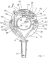
- eine Draufsicht der wesentlichen Bestandteile einer erfindungsgemäßen Verschaltungsanordnung in einem Zustand nach fertigem Verschalten (Betriebszustand),
- Fig. 2
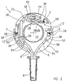
- eine Ansicht wie in Fig. 1, jedoch in einem Zustand zum Anschluß der Wicklungsdrahtenden (Anschlußzustand),
- Fig. 3
- eine gegenüber Fig. 1 und 2 verkleinerte Draufsicht eines scheibenförmigen Basisteils der Verschaltungsanordnung,
- Fig. 4
- eine Schnittansicht des Basisteils in der Schnittebene IV-IV gemäß Fig. 3,
- Fig. 5
- eine Draufsicht eines Deckels für die Temperaturwächter-Aufnahme des Basisteils,
- Fig. 6
- eine Schnittansicht des Deckels in der Schnittebene VI-VI gemäß Fig. 5,
- Fig. 7
- eine Draufsicht von zu dem Basisteil gehörenden Verbinderelementen der Verschaltungsanordnung,
- Fig. 8
- einen Schnitt durch den Bereich der Temperaturwächter-Aufnahme längs der Linie VIII-VIII in Fig. 1 in einer Ausführung mit eingesetztem Temperaturwächter,
- Fig. 9
- einen Schnitt durch den Bereich der Temperaturwächter-Aufnahme längs der Linie IX-IX in Fig. 1 ebenfalls in der Ausführung mit eingesetztem Temperaturwächter,
- Fig. 10
- eine Ansicht analog zu Fig. 8, jedoch in einer Ausführung ohne Temperaturwächter,
- Fig. 11
- eine Ansicht analog zu Fig. 9 in der Ausführung ohne Temperaturwächter und
- Fig. 12
- einen Halb-Axialschnitt durch einen Teilbereich eines mit der erfindungsgemäßen Verschaltungsanordnung ausgestatteten Elektromotors.
- Fig. 1
- 2 shows a plan view of the essential components of an interconnection arrangement according to the invention in a state after finished interconnection (operating state),
- Fig. 2
- 2 shows a view as in FIG. 1, but in a state for connecting the winding wire ends (connection state),
- Fig. 3
- 2 shows a plan view, reduced in comparison with FIGS. 1 and 2, of a disk-shaped base part of the circuit arrangement,
- Fig. 4
- 3 shows a sectional view of the base part in the sectional plane IV-IV according to FIG. 3,
- Fig. 5
- a plan view of a cover for the temperature monitor holder of the base part,
- Fig. 6
- 5 shows a sectional view of the cover in the sectional plane VI-VI according to FIG. 5,
- Fig. 7
- 2 shows a plan view of connector elements of the circuit arrangement belonging to the base part,
- Fig. 8
- 3 shows a section through the area of the temperature monitor receptacle along the line VIII-VIII in FIG. 1 in an embodiment with the temperature monitor inserted,
- Fig. 9
- 2 shows a section through the area of the temperature monitor receptacle along the line IX-IX in FIG. 1 also in the embodiment with the temperature monitor inserted,
- Fig. 10
- 8 shows a view analogous to FIG. 8, but in an embodiment without a temperature monitor,
- Fig. 11
- a view similar to FIG. 9 in the version without temperature monitor and
- Fig. 12
- a half-axial section through a portion of an electric motor equipped with the circuit arrangement according to the invention.
In den verschiedenen Figuren der Zeichnung sind gleiche Teile stets mit den gleichen Bezugszeichen versehen. Daher gilt jede eventuell nur einmal unter Bezugnahme auf eine der Zeichnungsfiguren vorkommende Beschreibung eines Teils analog auch bezüglich der anderen Zeichnungsfiguren, in denen dieses Teil mit dem entsprechenden Bezugszeichen ebenfalls zu erkennen ist.In the different figures of the drawing, the same parts are always provided with the same reference symbols. Therefore, each description of a part that possibly only occurs once with reference to one of the drawing figures also applies analogously to the other drawing figures, in which this part can also be recognized with the corresponding reference symbol.
Wie sich zunächst aus Fig. 1 ergibt, dient eine erfindungsgemäße Verschaltungsanordnung 1 zum Verbinden bzw. Verschalten von Drahtenden 2 einer Statorwicklung 4 (vgl. Fig. 12) insbesondere eines Elektro-Außenläufermotors mit Anschlußleitern 6 eines Motor-Anschlußkabels 8. Hierzu besteht die Verschaltungsanordnung 1 im wesentlichen aus einem vorzugsweise ringscheibenförmigen Basisteil 10 und daran bzw. darauf gehalterten, elektrischen Verbinderelementen 12, an denen die Drahtenden 2 und/oder die Anschlußleiter 6 elektrisch anschließbar sind.1, an
Das Basisteil 10 besteht aus einem elektrisch isolierenden Material, zweckmäßig Kunststoff, und weist eine vorzugsweise etwa zentrische Öffnung 14 auf, mit der das Basisteil 10 - siehe hierzu Fig. 12 - auf einem Stirnisolationsschaft 16 des Motors bzw. Stators so befestigbar ist, daß das scheibenförmige Basisteil 10 auch als Wickelkopfabdeckung fungiert.The
Zusätzlich zu den Verbinderelementen 12 ist zudem eine Aufnahme 18 für einen Temperaturwächter 20 vorgesehen. Es wird vorzugsweise ein Temperaturwächter 20 verwendet, der im wesentlichen als flacher, zylindrischer Körper ausgebildet ist. Hierzu weist die Aufnahme 18 eine entsprechende Innenkontur mit flacher, zylindrischer Form auf. Dies ist am besten in Fig. 3 und 4 zu erkennen. Zweckmäßigerweise ist die Aufnahme 18 durch entsprechende Raumform des bevorzugt als einstückiges Kunststoff-Formteil ausgebildeten Basisteils 10 gebildet.In addition to the
Zu den auf dem Basisteil 10 gehalterten Verbinderelementen 12 gehören nun erfindungsgemäß ein erstes Verbinderelement 22 und ein zweites Verbinderelement 24, wobei das zweite Verbinderelement 24 vorzugsweise in zwei geringfügig verschiedenen Ausführungsformen vorhanden ist; in den Fig. 7 bis 11 sind diese geringfügig verschiedenen Verbinderelemente mit den Bezugszeichen 24a und 24b versehen. Das erste Verbinderelement 22 weist nun erfindungsgemäß ein Kontaktfederelement 26 auf, welches im Bereich der Aufnahme 18 für den Temperaturwächter 20 mit einer Gegenkontaktfläche 28 des zweiten Verbinderelementes 24 elektrisch leitend verbunden ist. Erfindungsgemäß ist es somit möglich, wahlweise eine Ausführung mit oder ohne Temperaturwächter vorzusehen. Dies soll nun anhand der Fig. 7 bis 11 genauer erläutert werden.According to the invention, the
In Fig. 10 und 11 ist eine Ausführung ohne Temperaturwächter veranschaulicht. Hierbei ist das erste Verbinderelement 22 mit dem zweiten Verbinderelement 24a unmittelbar durch direkten Anlagekontakt des Kontaktfederelementes 26 an der Gegenkontaktfläche - hier mit 28a bezeichnet - verbunden. Vorzugsweise ist hierzu das zweite Verbinderelement 24a mit einem die Gegenkontaktfläche 28a aufweisenden Kontaktabschnitt 30a auf der dem Kontaktfederelement 26 zugekehrten Öffnungsseite der Aufnahme 18 auf einer dort gebildeten, vorzugsweise ringförmigen Auflagestufe 32 (siehe hierzu insbesondere Fig. 3 und 4) gegen eine von dem Kontaktfederelement 26 bewirkte Andruckkraft F abgestützt. Hierbei bildet somit der Kontaktabschnitt 30a praktisch eine Art Deckel für die bei dieser Motorausführung leer bleibende Aufnahme 18. Dies ist in den Fig. 10 und 11 gut zu erkennen.An embodiment without a temperature monitor is illustrated in FIGS. 10 and 11. In this case, the
In den Fig. 8 und 9 ist nun eine Anordnung mit Temperaturwächter 20 dargestellt. Hierbei ist das erste Verbinderelement 22 mittelbar über den in der Aufnahme 18 angeordneten Temperaturwächter 20 mit dem zweiten Verbinderelement 24b verbunden, wobei der Temperaturwächter 20 zwischen dem Kontaktfederelement 26 und der Gegenkontaktfläche 28b jeweils mit elektrischem Anlagekontakt angeordnet ist. Auch hierbei liegt das Kontaktfederelement 26 mit der Andruckkraft F auf dem Temperaturwächter 20 auf. Bei dieser Ausführung ist das zweite Verbinderelement 24b mit einem die Gegenkontaktfläche 28b aufweisenden Kontaktabschnitt 30b innerhalb der Aufnahme 18 auf der dem Kontaktfederelement 26 abgekehrten Seite des Temperaturwächters 20 angeordnet. Wie sich aus Fig. 7 ergibt, ist aus diesem Grund der Kontaktabschnitt 30b hinsichtlich seiner Flächengröße kleiner als der Kontaktabschnitt 30a der anderen Ausführungsform des zweiten Verbinderelementes 24a ausgebildet. Hierdurch kann der Kontaktabschnitt 30b in die Aufnahme 18 eingesetzt werden, anstatt auf der Auflagestufe 32 aufzuliegen. Zweckmäßigerweise liegt der Kontaktabschnitt 30b auf einer die Aufnahme begrenzenden Bodenwandung 34 des Basisteils 10 auf. Dabei ist es vorteilhaft, wenn in dieser Bodenwandung 34 eine Lochöffnung 36 derart gebildet ist, daß im mit dem Stator verbundenen Zustand des Basisteils 10 - siehe hierzu Fig. 12 - der in der Aufnahme 18 angeordnete Temperaturwächter 20 durch die Lochöffnung 36 hindurch mit der Wärme der Statorwicklung 4 beaufschlagt wird, und zwar mittelbar über den Kontaktabschnitt 30b des zweiten Verbinderelementes 24b sowie gegebenenfalls über eine Schaltungsisolation 68. Aufgrund der Lochöffnung 36 verbleibt somit von der Bodenwandung 34 lediglich ein schmaler, radial nach innen ragender Ringsteg zur Abstützung des Kontaktabschnittes 30b und des Temperaturwächters 20 gegen die Kraft F.8 and 9, an arrangement with temperature monitor 20 is now shown. Here, the
Es ist zweckmäßig, wenn die Verbinderelemente 12 als Blechstanzteile ausgebildet sind, die in im wesentlichen flach auf dem ringscheibenförmigen Basisteil liegender Anordnung gehaltert sind. Die Halterung erfolgt vorzugsweise durch Stiftansätze 38 des Basisteils 10, die zur Erzeugung von Formschlußverbindungen durch Löcher 40 der Verbinderelemente 12 geführt und insbesondere thermisch-mechanisch "nietkopfartig" verformt sind ("verstemmt"). Die Erwärmung kann mit Vorteil im Ultraschallverfahren erfolgen. In den Zeichnungen sind die Stiftansätze 38 in ihrem noch nicht verstemmten Zustand dargestellt. In Fig. 8 und 10 ist jedoch auch der verstemmte Zustand punktiert angedeutet.It is expedient if the
Wie sich nun weiterhin aus Fig. 1, 2 und 7 ergibt, weist das erste Verbinderelement 22 einen den Bereich der Temperaturwächter-Aufnahme 18 überdeckenden Brückenabschnitt 42 auf, aus dem das Kontaktfederelement 26 zungenartig freigeschnitten oder freigespart bzw. freigestanzt und in Richtung der Aufnahme 18 so gebogen ist, daß es mit seinem freien Ende den Temperaturwächter 20 oder den Kontaktabschnitt 30a kontaktieren kann und dann mit der Kraft F anliegt. Die Bogenform des Kontaktfederelementes 26 ist in den Fig. 8 bis 11 gut zu erkennen.1, 2 and 7, the
Hierbei ist es besonders vorteilhaft, wenn zusätzlich ein die Aufnahme 18 verschließender Deckel 44 aus einem elektrisch isolierenden Material vorgesehen ist, wobei dieser Deckel 44 eine von dem Kontaktfederelement 26 durchgriffene Lochöffnung 46 aufweist. Der Deckel 44 ist gesondert in den Fig. 5 und 6 dargestellt. Hierbei liegt nun der Brückenabschnitt 42 des ersten Verbinderelementes 22 auf dem Deckel 44 auf und ist somit gegenüber dem übrigen Teil, der auf der Oberfläche des Basisteils 10 aufliegt, nach oben verkröpft. Vorzugsweise sind hierbei der Deckel 44 und der Brückenabschnitt 42 gemeinsam an dem Basisteil 10 über Stiftansätze 38 gehaltert. Dies ist in Fig. 1 und 2 zu erkennen. Zwischen dem Basisteil 10 und dem Deckel 44 ist hierbei eine schlitzartige Durchführöffnung 48 für den Kontaktabschnitt 30a, b des zweiten Verbinderelementes 24a, b gebildet (vgl. hierzu Fig. 3, 5, 9 und 11).It is particularly advantageous here if a
Wie sich nun aus Fig. 7 weiterhin ergibt, gehören zu den Verbinderelementen 12 noch ein drittes Verbinderelement 50 und ein viertes Verbinderelement 52.As can further be seen from FIG. 7, the
Zum Anschluß der Anschlußleiter 6 weisen nun das erste Verbinderelement 22, das dritte Verbinderelement 50 und das vierte Verbinderelement 52 jeweils einen insbesondere als Krimpabschnitt 54 ausgebildeten Anschluß auf. Ferner weisen zum Anschluß der Drahtenden 2 der Statorwicklung 4 das zweite Verbinderelement 24a bzw. b, das dritte Verbinderelement 50 und das vierte Verbinderelement 52 jeweils eine Anschlußfahne 56 auf, die an ihrem freien Ende einen insbesondere als Klemmzunge 58 ausgebildeten Anschluß zur elektrisch leitenden Verbindung mit dem jeweiligen Drahtende 2 besitzt. Hierbei ist nun erfindungsgemäß vorgesehen, daß jede Anschlußfahne 56 zusammen mit dem angeschlossenen Drahtende 2 aus einer mit dem übrigen, im wesentlichen parallel auf einer Auflageebene des Basisteils 10 liegenden Teil des jeweiligen Verbinderelementes 12 einen Winkel von insbesondere etwa 90° einschließenden Anschlußstellung - siehe Fig. 2 - derart in eine ebenfalls im wesentlichen auf dem Basisteil 10 liegende Betriebsstellung - in Fig. 1 dargestellt - umgebogen ist, daß hierdurch das Drahtende 2 einen ausgeprägten, eine mechanische Spannung vermeidenden Lockerungsbogen 60 erhält (Fig. 1). Hierbei sind die Anschlußfahnen 56 über Biegelinien 62 (in Fig. 1 gestrichelt eingezeichnet) mit dem übrigen Teil des Verbinderelementes 12 verbunden. Bei dieser vorteilhaften Ausführungsform - die grundsätzlich für jeden Motor auch unabhängig von den eine Montage mit oder ohne Temperaturwächter ermöglichenden Merkmalen des Hauptanspruches geeignet ist - werden die Drahtenden 2 somit in einer etwa senkrecht von dem Basisteil 10 hochstehenden Anordnung der Anschlußfahnen 56, d.h. in der Anschlußstellung, an den Klemmzungen 58 angeschlossen und insbesondere zusätzlich verschweißt. Nun werden die mit den Drahtenden 2 verbundenen Anschlußfahnen 56 in die Ebene des Basisteils 10 umgebogen, wodurch die Wicklungsdrähte mechanisch entlastet werden, so daß Drahtbrüche aufgrund von eventuell auftretenden mechanischen Schwingungen vorteilhafterweise vermieden werden.To connect the connecting
Abschließend erfolgt vorzugsweise eine Abdeckung des mit den Verbinderelementen 12 versehenen Basisteils 10 mit einer isolierenden Abdeckung 64, die insbesondere ringscheibenförmig mit einem äußeren, sich axial in Richtung des Basisteils 10 erstreckenden Umfangsrand 66 ausgebildet ist (siehe Fig. 12). Die Abdeckung 64 wird hierbei auf geeignete Weise, z.B. stoffschlüssig, an dem Basisteil 10 und/oder an dem Stirnisolationsschaft 16 befestigt.Finally, the
Die Erfindung ist nicht auf die dargestellten und beschriebenen Ausführungsbeispiele beschränkt, sondern umfaßt auch alle im Sinne der Erfindung gleichwirkenden Ausführungen. Ferner ist die Erfindung bislang auch noch nicht auf die im Anspruch 1 definierte Merkmalskombination beschränkt, sondern kann auch durch jede beliebige andere Kombination von bestimmten Merkmalen aller insgesamt offenbarten Einzelmerkmalen definiert sein. Dies bedeutet, daß grundsätzlich praktisch jedes Einzelmerkmal des Anspruchs 1 weggelassen bzw. durch mindestens ein an anderer Stelle der Anmeldung offenbartes Einzelmerkmal ersetzt werden kann. Insofern ist der Anspruch 1 lediglich als ein erster Formulierungsversuch für eine Erfindung zu verstehen.The invention is not limited to the exemplary embodiments shown and described, but also encompasses all embodiments having the same effect in the sense of the invention. Furthermore, the invention has not yet been limited to the combination of features defined in
Claims (15)
dadurch gekennzeichnet, daß ein erstes (22) der Verbinderelemente (12) ein Kontaktfederelement (26) aufweist, welches im Bereich der Aufnahme (18) für den Temperaturwächter (20) mit einer Gegenkontaktfläche (28; 28a,28b) eines zweiten Verbinderelementes (24; 24a,24b) elektrisch leitend verbunden ist.Circuit arrangement (1) for connecting wire ends (2) of a stator winding (4) of an electric motor with connecting conductors (6), with a base part (10), in particular disk-shaped, consisting of electrically insulating material, and with electrical connector elements held on the base part (10) (12) for connecting the wire ends (2) or the connecting conductors (6) and with a receptacle (18) for a temperature monitor (20),
characterized in that a first (22) of the connector elements (12) has a contact spring element (26) which, in the region of the receptacle (18) for the temperature monitor (20), has a mating contact surface (28; 28a, 28b) of a second connector element (24 ; 24a, 24b) is electrically conductively connected.
dadurch gekennzeichnet, daß das erste Verbinderelement (22) mit dem zweiten Verbinderelement (24a) unmittelbar durch direkten Anlagekontakt des Kontaktfederelementes (26) an der Gegenkontaktfläche (28a) verbunden ist.Circuit arrangement according to claim 1,
characterized in that the first connector element (22) is connected to the second connector element (24a) directly by direct contact of the contact spring element (26) on the mating contact surface (28a).
dadurch gekennzeichnet, daß das zweite Verbinderelement (24a) mit einem die Gegenkontaktfläche (28a) aufweisenden Kontaktabschnitt (30a) auf der dem Kontaktfederelement (26) zugekehrten Öffnungsseite der Aufnahme (18), insbesondere auf einer dort gebildeten Auflagestufe (32), gegen eine von dem Kontaktfederelement (26) bewirkte Andruckkraft (F) abgestützt ist.Circuit arrangement according to claim 2,
characterized in that the second connector element (24a) with a contact section (30a) having the counter-contact surface (28a) on the opening side of the receptacle (18) facing the contact spring element (26), in particular on a support step (32) formed there, against one of the contact spring element (26) caused contact pressure (F) is supported.
dadurch gekennzeichnet, daß das erste Verbinderelement (22) mittelbar über den in der Aufnahme (18) angeordneten Temperaturwächter (20) mit dem zweiten Verbinderelement (24b) verbunden ist, wobei der Temperaturwächter (20) zwischen dem Kontaktfederelement (26) und der Gegenkontaktfläche (28b) jeweils mit elektrischem Anlagekontakt angeordnet ist.Circuit arrangement according to claim 1,
characterized in that the first connector element (22) is connected indirectly to the second connector element (24b) via the temperature monitor (20) arranged in the receptacle (18), the temperature monitor (20) between the contact spring element (26) and the mating contact surface ( 28b) is arranged with an electrical system contact.
dadurch gekennzeichnet, daß das zweite Verbinderelement (24b) mit einem die Gegenkontaktfläche (28b) aufweisenden Kontaktabschnitt (30b) innerhalb der Aufnahme (18) auf der dem Kontaktfederelement (26) abgekehrten Seite des Temperaturwächters (20) angeordnet ist.Circuit arrangement according to claim 4,
characterized in that the second connector element (24b) is arranged with a contact section (30b) having the counter-contact surface (28b) within the receptacle (18) on the side of the temperature monitor (20) remote from the contact spring element (26).
dadurch gekennzeichnet, daß die Verbinderelemente (12) als Blechstanzteile ausgebildet sind, die in im wesentlichen flach auf dem scheibenförmigen Basisteil (10) liegender Anordnung gehaltert sind, und zwar vorzugsweise durch Stiftansätze (38) des Basisteils (10), die zur Erzeugung von Formschlußverbindungen durch Löcher (40) der Verbinderelemente (12) geführt und insbesondere thermisch-mechanisch verformt sind.Circuit arrangement according to one or more of claims 1 to 5,
characterized in that the connector elements (12) are designed as stamped sheet metal parts which are held in an essentially flat arrangement lying on the disc-shaped base part (10), preferably by means of pin attachments (38) of the base part (10) which are used to produce positive connections through holes (40) of the connector elements (12) and in particular thermo-mechanically deformed.
dadurch gekennzeichnet, daß das erste Verbinderelement (22) einen den Bereich der Temperaturwächter-Aufnahme (18) überdeckenden Brückenabschnitt (42) aufweist, aus dem das Kontaktfederelement (26) als Zunge freigeschnitten oder freigespart und in Richtung der Aufnahme (18) gebogen ist.Circuit arrangement according to one or more of claims 1 to 6,
characterized in that the first connector element (22) has a bridge section (42) covering the area of the temperature monitor receptacle (18), from which the contact spring element (26) is cut or freed as a tongue and bent in the direction of the receptacle (18).
gekennzeichnet durch einen die Aufnahme (18) verschließenden Deckel (44), der eine von dem Kontaktfederelement (26) durchgriffene Lochöffnung (46) aufweist.Circuit arrangement according to one or more of claims 1 to 7,
characterized by a cover (44) closing the receptacle (18) and having a hole opening (46) through which the contact spring element (26) passes.
dadurch gekennzeichnet, daß der Brückenabschnitt (42) des ersten Verbinderelementes (22) auf dem Deckel (44) liegend angeordnet und vorzugsweise gemeinsam mit dem Deckel (44) an dem Basisteil (10) gehaltert ist.Circuit arrangement according to Claim 7 or 8,
characterized in that the bridge section (42) of the first connector element (22) is arranged lying on the cover (44) and preferably is held together with the cover (44) on the base part (10).
dadurch gekennzeichnet, daß zwischen dem Basisteil (10) und dem Deckel (44) eine schlitzartige Durchführöffnung (48) für den Kontaktabschnitt (30a,b) des zweiten Verbinderelementes (24a, b) gebildet ist.Circuit arrangement according to Claim 8 or 9,
characterized in that between the base part (10) and the cover (44) a slot-like through opening (48) for the contact section (30a, b) of the second connector element (24a, b) is formed.
dadurch gekennzeichnet, daß das Basisteil (10) im Bereich der Aufnahme (18) auf deren dem Kontaktfederelement (26) abgekehrten Seite eine Bodenwandung (34) mit einer Lochöffnung (36) derart aufweist, daß im mit dem Stator verbundenen Zustand des Basisteils (10) der in der Aufnahme (18) angeordnete Temperaturwächter (20) durch die Lochöffnung (36) hindurch mit der Wärme der Statorwicklung (4) beaufschlagt wird.Circuit arrangement according to one or more of claims 1 to 10,
characterized in that the base part (10) in the region of the receptacle (18) on its side facing away from the contact spring element (26) has a bottom wall (34) with a hole opening (36) such that when the base part (10 ) the temperature monitor (20) arranged in the receptacle (18) is subjected to the heat of the stator winding (4) through the hole opening (36).
dadurch gekennzeichnet, daß zumindest einige der Verbinderelemente (12) zum Anschluß der Drahtenden (2) der Statortwicklung (4) jeweils eine Anschlußfahne (56) aufweisen, die einen insbesondere als Klemmzunge (58) ausgebildeten Anschluß zur elektrisch leitenden Verbindung mit dem jeweiligen Drahtende (2) besitzt.Circuit arrangement in particular according to one or more of claims 1 to 11,
characterized in that at least some of the connector elements (12) for connecting the wire ends (2) of the stator winding (4) each have a connection tab (56) which has a connection, in particular in the form of a clamping tongue (58), for the electrically conductive connection to the respective wire end ( 2) has.
dadurch gekennzeichnet, daß jede Anschlußfahne (56) zusammen mit dem angeschlossenen Drahtende (2) aus einer mit dem übrigen, im wesentlichen parallel auf einer Auflageebene des Basisteils (10) liegenden Teil des Verbinderelementes (12) einen Winkel von insbesondere etwa 90° einschließenden Anschlußstellung (Fig. 2) derart in eine im wesentlichen auf der Auflageebene liegende Betriebsstellung (Fig. 1) umgebogen ist, daß hierdurch das Drahtende (2) einen ausgeprägten, eine mechanische Spannung vermeidenden Lockerungsbogen (60) erhält.Circuit arrangement according to claim 12,
characterized in that each terminal lug (56) together with the connected wire end (2) from a part of the connector element (12) enclosing an angle of in particular approximately 90 ° with the rest of the part of the connector element (12) lying essentially parallel on a support plane of the base part (10) (FIG. 2) is bent into an operating position (FIG. 1) lying essentially on the support plane in such a way that the wire end (2) receives a pronounced loosening bow (60) that avoids mechanical tension.
dadurch gekennzeichnet, daß zumindest einige der Verbinderelemente (12) zum Anschluß der Anschlußleiter (6) jeweils einen insbesondere als Krimpabschnitt (54) ausgebildeten Anschluß aufweisen.Circuit arrangement according to one or more of claims 1 to 13,
characterized in that at least some of the connector elements (12) for connecting the connecting conductors (6) each have a connection, in particular a crimp section (54).
gekennzeichnet durch eine isolierende Abdeckung (64), die in einer das Basisteil (10) auf seiner der Statorwicklung (4) abgekehrten Oberseite überdeckenden Anordnung befestigbar ist.Circuit arrangement according to one or more of claims 1 to 14,
characterized by an insulating cover (64) which can be fastened in an arrangement covering the base part (10) on its upper side facing away from the stator winding (4).
Applications Claiming Priority (2)
| Application Number | Priority Date | Filing Date | Title |
|---|---|---|---|
| DE19505557A DE19505557A1 (en) | 1995-02-18 | 1995-02-18 | Circuit arrangement for an electric motor |
| DE19505557 | 1995-02-18 |
Publications (3)
| Publication Number | Publication Date |
|---|---|
| EP0727864A2 true EP0727864A2 (en) | 1996-08-21 |
| EP0727864A3 EP0727864A3 (en) | 1998-05-06 |
| EP0727864B1 EP0727864B1 (en) | 2003-01-02 |
Family
ID=7754355
Family Applications (1)
| Application Number | Title | Priority Date | Filing Date |
|---|---|---|---|
| EP96100710A Expired - Lifetime EP0727864B1 (en) | 1995-02-18 | 1996-01-18 | Electric motor interconnection board |
Country Status (3)
| Country | Link |
|---|---|
| EP (1) | EP0727864B1 (en) |
| DE (2) | DE19505557A1 (en) |
| ES (1) | ES2187583T3 (en) |
Cited By (14)
| Publication number | Priority date | Publication date | Assignee | Title |
|---|---|---|---|---|
| EP1134876A1 (en) * | 2000-03-06 | 2001-09-19 | ebm Werke GmbH & Co. | Electric motor interconnection board |
| WO2002071579A1 (en) * | 2001-03-01 | 2002-09-12 | Inarca S.P.A. | Device for connecting and insulating a thermal protector for electrical windings of motors |
| EP1486671A1 (en) * | 2002-02-19 | 2004-12-15 | Ubukata Industries Co., Ltd | Thermally-actuated switch |
| EP0993095B1 (en) * | 1998-10-06 | 2005-04-27 | ebm-papst Mulfingen GmbH & Co.KG | Stator for electric motor |
| JP2006203965A (en) * | 2005-01-18 | 2006-08-03 | Mitsubishi Electric Corp | Motor |
| EP1727261A1 (en) * | 2005-05-23 | 2006-11-29 | ebm-papst Mulfingen GmbH & Co.KG | Stator for an electric motor |
| CN103259368A (en) * | 2013-01-06 | 2013-08-21 | 广东威灵电机制造有限公司 | Motor and installation seat for motor |
| EP2654183A1 (en) | 2012-04-20 | 2013-10-23 | ebm-papst Mulfingen GmbH & Co. KG | Wiring device for an electric motor |
| CN105932848A (en) * | 2015-02-27 | 2016-09-07 | 博泽沃尔兹堡汽车零部件有限公司 | Stator Component Group For Electric Motor |
| EP3297134A4 (en) * | 2015-09-17 | 2018-05-23 | Aisin AW Co., Ltd. | Rotary electrical machine stator |
| WO2019115224A1 (en) * | 2017-12-13 | 2019-06-20 | Continental Automotive Gmbh | Spring clamp for fitting onto an electrical conductor of an electric machine |
| WO2019228880A1 (en) * | 2018-05-28 | 2019-12-05 | Zf Friedrichshafen Ag | Stator of an electrical machine, comprising a temperature sensor, and electrical machine comprising such a stator |
| WO2019228881A1 (en) * | 2018-05-28 | 2019-12-05 | Zf Friedrichshafen Ag | Stator of an electrical machine, comprising an arrangement for temperature detection, and electrical machine comprising such a stator |
| WO2020216405A1 (en) * | 2019-04-26 | 2020-10-29 | Schaeffler Technologies AG & Co. KG | Electric machine |
Families Citing this family (3)
| Publication number | Priority date | Publication date | Assignee | Title |
|---|---|---|---|---|
| DE10206692A1 (en) | 2002-02-18 | 2003-08-28 | Siemens Ag | Fixing unit for electric motor e.g. for throttle valve support, consists of multi-part electrically conducting base body with power supply and motor connections mounted in non-conducting carrier with fixing holes |
| DE202007007391U1 (en) | 2007-05-24 | 2008-10-02 | Ebm-Papst Mulfingen Gmbh & Co. Kg | Stator for an electric motor |
| DE202010002664U1 (en) * | 2010-02-23 | 2011-07-12 | Brose Fahrzeugteile GmbH & Co. Kommanditgesellschaft, Würzburg | Electric motor for driving a motor vehicle component |
Citations (4)
| Publication number | Priority date | Publication date | Assignee | Title |
|---|---|---|---|---|
| EP0548610A1 (en) * | 1991-12-20 | 1993-06-30 | Licentia Patent-Verwaltungs-GmbH | Electric motor with thermal protection switch |
| EP0603478A1 (en) * | 1992-12-23 | 1994-06-29 | EBM ELEKTROBAU MULFINGEN GmbH & Co. | Interconnection board for joining the wire ends of a stator winding |
| DE4422988A1 (en) * | 1993-06-30 | 1995-01-19 | Jeco Kk | Motor |
| EP0638982A2 (en) * | 1993-06-15 | 1995-02-15 | Mabuchi Motor Kabushiki Kaisha | Miniature motor |
-
1995
- 1995-02-18 DE DE19505557A patent/DE19505557A1/en not_active Withdrawn
-
1996
- 1996-01-18 DE DE59610013T patent/DE59610013D1/en not_active Expired - Lifetime
- 1996-01-18 ES ES96100710T patent/ES2187583T3/en not_active Expired - Lifetime
- 1996-01-18 EP EP96100710A patent/EP0727864B1/en not_active Expired - Lifetime
Patent Citations (4)
| Publication number | Priority date | Publication date | Assignee | Title |
|---|---|---|---|---|
| EP0548610A1 (en) * | 1991-12-20 | 1993-06-30 | Licentia Patent-Verwaltungs-GmbH | Electric motor with thermal protection switch |
| EP0603478A1 (en) * | 1992-12-23 | 1994-06-29 | EBM ELEKTROBAU MULFINGEN GmbH & Co. | Interconnection board for joining the wire ends of a stator winding |
| EP0638982A2 (en) * | 1993-06-15 | 1995-02-15 | Mabuchi Motor Kabushiki Kaisha | Miniature motor |
| DE4422988A1 (en) * | 1993-06-30 | 1995-01-19 | Jeco Kk | Motor |
Cited By (29)
| Publication number | Priority date | Publication date | Assignee | Title |
|---|---|---|---|---|
| EP0993095B1 (en) * | 1998-10-06 | 2005-04-27 | ebm-papst Mulfingen GmbH & Co.KG | Stator for electric motor |
| EP1134876A1 (en) * | 2000-03-06 | 2001-09-19 | ebm Werke GmbH & Co. | Electric motor interconnection board |
| WO2002071579A1 (en) * | 2001-03-01 | 2002-09-12 | Inarca S.P.A. | Device for connecting and insulating a thermal protector for electrical windings of motors |
| US6744160B2 (en) | 2001-03-01 | 2004-06-01 | Inarca S.P.A. | Device for connecting and insulating a thermal protector for electrical windings of motors |
| US7345571B2 (en) | 2002-02-19 | 2008-03-18 | Ubukata Industries Co., Ltd. | Thermally-actuated switch |
| EP1486671A1 (en) * | 2002-02-19 | 2004-12-15 | Ubukata Industries Co., Ltd | Thermally-actuated switch |
| EP1486671A4 (en) * | 2002-02-19 | 2005-09-14 | Ubukata Ind Co Ltd | Thermally-actuated switch |
| JP2006203965A (en) * | 2005-01-18 | 2006-08-03 | Mitsubishi Electric Corp | Motor |
| EP1727261A1 (en) * | 2005-05-23 | 2006-11-29 | ebm-papst Mulfingen GmbH & Co.KG | Stator for an electric motor |
| US7402925B2 (en) | 2005-05-23 | 2008-07-22 | Ebm-Papst Mulfingen Gmbh & Co Kg | Stator for an electric motor having a temperature monitor |
| CN100574053C (en) * | 2005-05-23 | 2009-12-23 | 埃布姆-派斯特穆尔芬根股份有限两合公司 | motor stator |
| KR101114016B1 (en) * | 2005-05-23 | 2012-02-21 | 에베엠-펩스트 물핑겐 게엠베하 운트 코. 카게 | Statror for an electric motor |
| EP2654183A1 (en) | 2012-04-20 | 2013-10-23 | ebm-papst Mulfingen GmbH & Co. KG | Wiring device for an electric motor |
| CN103259368B (en) * | 2013-01-06 | 2016-03-23 | 广东威灵电机制造有限公司 | Motor and the mount pad for motor |
| CN103259368A (en) * | 2013-01-06 | 2013-08-21 | 广东威灵电机制造有限公司 | Motor and installation seat for motor |
| CN105932848B (en) * | 2015-02-27 | 2019-05-21 | 博泽沃尔兹堡汽车零部件有限公司 | Stator structure component for motor |
| CN105932848A (en) * | 2015-02-27 | 2016-09-07 | 博泽沃尔兹堡汽车零部件有限公司 | Stator Component Group For Electric Motor |
| US10211695B2 (en) | 2015-02-27 | 2019-02-19 | Brose Fahrzeugteile Gmbh & Co. Kommanditgesellschaft, Wuerzburg | Stator component group for an electric motor |
| US10454348B2 (en) | 2015-09-17 | 2019-10-22 | Aisin Aw Co., Ltd. | Stator for rotating electrical machine |
| EP3297134A4 (en) * | 2015-09-17 | 2018-05-23 | Aisin AW Co., Ltd. | Rotary electrical machine stator |
| WO2019115224A1 (en) * | 2017-12-13 | 2019-06-20 | Continental Automotive Gmbh | Spring clamp for fitting onto an electrical conductor of an electric machine |
| US11502582B2 (en) | 2017-12-13 | 2022-11-15 | Vitesco Technologies GmbH | Spring clamp for fitting onto an electrical conductor of an electric machine |
| WO2019228880A1 (en) * | 2018-05-28 | 2019-12-05 | Zf Friedrichshafen Ag | Stator of an electrical machine, comprising a temperature sensor, and electrical machine comprising such a stator |
| WO2019228881A1 (en) * | 2018-05-28 | 2019-12-05 | Zf Friedrichshafen Ag | Stator of an electrical machine, comprising an arrangement for temperature detection, and electrical machine comprising such a stator |
| CN112166545A (en) * | 2018-05-28 | 2021-01-01 | 采埃孚股份公司 | Stator of an electric machine having a device for detecting temperature, and electric machine |
| US11476738B2 (en) | 2018-05-28 | 2022-10-18 | Zf Friedrichshafen Ag | Stator of an electrical machine, comprising an arrangement for temperature detection, and electrical machine comprising such a stator |
| CN112166545B (en) * | 2018-05-28 | 2024-03-12 | 采埃孚股份公司 | Stator of electric machine with device for detecting temperature and electric machine |
| WO2020216405A1 (en) * | 2019-04-26 | 2020-10-29 | Schaeffler Technologies AG & Co. KG | Electric machine |
| US20220311312A1 (en) * | 2019-04-26 | 2022-09-29 | Schaeffler Technologies AG & Co. KG | Electric machine |
Also Published As
| Publication number | Publication date |
|---|---|
| DE19505557A1 (en) | 1996-08-22 |
| DE59610013D1 (en) | 2003-02-06 |
| EP0727864B1 (en) | 2003-01-02 |
| EP0727864A3 (en) | 1998-05-06 |
| ES2187583T3 (en) | 2003-06-16 |
Similar Documents
| Publication | Publication Date | Title |
|---|---|---|
| EP1727261B2 (en) | Stator for an electric motor | |
| EP0727864A2 (en) | Electric motor interconnection board | |
| EP0634888B1 (en) | Plug-in unit, particularly relay module for motor vehicles | |
| EP2082472B1 (en) | Electric motor | |
| EP3236564B1 (en) | Contact-making arrangement between a stator and a printed circuit board | |
| DE202007007391U1 (en) | Stator for an electric motor | |
| EP0959529B1 (en) | Electrical connecting unit | |
| EP0755584B1 (en) | Power supply system for an electric motor with four brushes | |
| WO2008015246A1 (en) | Stator having a switch disc | |
| EP0797859A1 (en) | Brush support plate | |
| EP1012914A1 (en) | Plug-in contact | |
| DE19748150B4 (en) | Spindle motor with contacting | |
| EP0822337B1 (en) | Mounting device for electric fan, particularly a miniature fan | |
| DE4110474A1 (en) | Electric motor with multi-pole socket - has socket with connection contacts connected to beginnings and ends of motor field winding wires | |
| DE19902433C1 (en) | Commutator motor has brush bridge with holder slot for capacitor connecting wire connected to housing via contact element with plate with slot as part of clamp blade connector | |
| EP0410119B1 (en) | Temperature switch with bimetallic switch mechanism | |
| EP0676826A1 (en) | Electrical contact member for connecting at least two conductors | |
| DE60008977T2 (en) | Switching device with an AC inlet and an AC switch | |
| DE19914308A1 (en) | Electrical connector for insulated or stripped wire | |
| DE10025295C2 (en) | Connectors, in particular for airbag ignition systems | |
| EP1134876B1 (en) | Electric motor interconnection board | |
| EP1083627B1 (en) | Electrical connector assembly | |
| WO1998036484A1 (en) | Brush-holding device | |
| DE602004008094T2 (en) | ELECTRICAL CONNECTOR FOR A FLEXIBLE FLAT LEADER AND SWITCHING DEVICE | |
| CH673917A5 (en) |
Legal Events
| Date | Code | Title | Description |
|---|---|---|---|
| PUAI | Public reference made under article 153(3) epc to a published international application that has entered the european phase |
Free format text: ORIGINAL CODE: 0009012 |
|
| AK | Designated contracting states |
Kind code of ref document: A2 Designated state(s): CH DE ES FR GB IT LI NL SE |
|
| 17P | Request for examination filed |
Effective date: 19970219 |
|
| RAP1 | Party data changed (applicant data changed or rights of an application transferred) |
Owner name: EBM WERKE GMBH & CO. |
|
| PUAL | Search report despatched |
Free format text: ORIGINAL CODE: 0009013 |
|
| AK | Designated contracting states |
Kind code of ref document: A3 Designated state(s): CH DE ES FR GB IT LI NL SE |
|
| 17Q | First examination report despatched |
Effective date: 20000905 |
|
| GRAG | Despatch of communication of intention to grant |
Free format text: ORIGINAL CODE: EPIDOS AGRA |
|
| GRAG | Despatch of communication of intention to grant |
Free format text: ORIGINAL CODE: EPIDOS AGRA |
|
| GRAH | Despatch of communication of intention to grant a patent |
Free format text: ORIGINAL CODE: EPIDOS IGRA |
|
| RAP1 | Party data changed (applicant data changed or rights of an application transferred) |
Owner name: EBM WERKE GMBH & CO. KG |
|
| GRAH | Despatch of communication of intention to grant a patent |
Free format text: ORIGINAL CODE: EPIDOS IGRA |
|
| GRAA | (expected) grant |
Free format text: ORIGINAL CODE: 0009210 |
|
| AK | Designated contracting states |
Kind code of ref document: B1 Designated state(s): CH DE ES FR GB IT LI NL SE |
|
| REG | Reference to a national code |
Ref country code: GB Ref legal event code: FG4D Free format text: 20030102:NOT ENGLISH |
|
| REG | Reference to a national code |
Ref country code: CH Ref legal event code: NV Representative=s name: BRAUN & PARTNER PATENT-, MARKEN-, RECHTSANWAELTE Ref country code: CH Ref legal event code: EP |
|
| REF | Corresponds to: |
Ref document number: 59610013 Country of ref document: DE Date of ref document: 20030206 Kind code of ref document: P |
|
| GBT | Gb: translation of ep patent filed (gb section 77(6)(a)/1977) |
Effective date: 20030313 |
|
| ET | Fr: translation filed | ||
| REG | Reference to a national code |
Ref country code: ES Ref legal event code: FG2A Ref document number: 2187583 Country of ref document: ES Kind code of ref document: T3 |
|
| PLBE | No opposition filed within time limit |
Free format text: ORIGINAL CODE: 0009261 |
|
| STAA | Information on the status of an ep patent application or granted ep patent |
Free format text: STATUS: NO OPPOSITION FILED WITHIN TIME LIMIT |
|
| 26N | No opposition filed |
Effective date: 20031003 |
|
| PG25 | Lapsed in a contracting state [announced via postgrant information from national office to epo] |
Ref country code: IT Free format text: LAPSE BECAUSE OF NON-PAYMENT OF DUE FEES;WARNING: LAPSES OF ITALIAN PATENTS WITH EFFECTIVE DATE BEFORE 2007 MAY HAVE OCCURRED AT ANY TIME BEFORE 2007. THE CORRECT EFFECTIVE DATE MAY BE DIFFERENT FROM THE ONE RECORDED. Effective date: 20050118 |
|
| PGRI | Patent reinstated in contracting state [announced from national office to epo] |
Ref country code: IT Effective date: 20091201 |
|
| PGFP | Annual fee paid to national office [announced via postgrant information from national office to epo] |
Ref country code: CH Payment date: 20111230 Year of fee payment: 17 |
|
| PGFP | Annual fee paid to national office [announced via postgrant information from national office to epo] |
Ref country code: FR Payment date: 20120119 Year of fee payment: 17 |
|
| PGFP | Annual fee paid to national office [announced via postgrant information from national office to epo] |
Ref country code: GB Payment date: 20120130 Year of fee payment: 17 Ref country code: SE Payment date: 20120104 Year of fee payment: 17 |
|
| PGFP | Annual fee paid to national office [announced via postgrant information from national office to epo] |
Ref country code: NL Payment date: 20120106 Year of fee payment: 17 |
|
| PGFP | Annual fee paid to national office [announced via postgrant information from national office to epo] |
Ref country code: ES Payment date: 20120120 Year of fee payment: 17 |
|
| REG | Reference to a national code |
Ref country code: NL Ref legal event code: V1 Effective date: 20130801 |
|
| REG | Reference to a national code |
Ref country code: CH Ref legal event code: PL |
|
| REG | Reference to a national code |
Ref country code: SE Ref legal event code: EUG |
|
| GBPC | Gb: european patent ceased through non-payment of renewal fee |
Effective date: 20130118 |
|
| REG | Reference to a national code |
Ref country code: FR Ref legal event code: ST Effective date: 20130930 |
|
| PG25 | Lapsed in a contracting state [announced via postgrant information from national office to epo] |
Ref country code: NL Free format text: LAPSE BECAUSE OF NON-PAYMENT OF DUE FEES Effective date: 20130801 Ref country code: LI Free format text: LAPSE BECAUSE OF NON-PAYMENT OF DUE FEES Effective date: 20130131 Ref country code: CH Free format text: LAPSE BECAUSE OF NON-PAYMENT OF DUE FEES Effective date: 20130131 Ref country code: SE Free format text: LAPSE BECAUSE OF NON-PAYMENT OF DUE FEES Effective date: 20130119 |
|
| PG25 | Lapsed in a contracting state [announced via postgrant information from national office to epo] |
Ref country code: FR Free format text: LAPSE BECAUSE OF NON-PAYMENT OF DUE FEES Effective date: 20130131 Ref country code: GB Free format text: LAPSE BECAUSE OF NON-PAYMENT OF DUE FEES Effective date: 20130118 |
|
| REG | Reference to a national code |
Ref country code: ES Ref legal event code: FD2A Effective date: 20140324 |
|
| PG25 | Lapsed in a contracting state [announced via postgrant information from national office to epo] |
Ref country code: ES Free format text: LAPSE BECAUSE OF NON-PAYMENT OF DUE FEES Effective date: 20130119 |
|
| PGFP | Annual fee paid to national office [announced via postgrant information from national office to epo] |
Ref country code: IT Payment date: 20150128 Year of fee payment: 20 Ref country code: DE Payment date: 20150131 Year of fee payment: 20 |
|
| REG | Reference to a national code |
Ref country code: DE Ref legal event code: R071 Ref document number: 59610013 Country of ref document: DE |