EP0727652A2 - Engine control unit for an internal combustion engine - Google Patents
Engine control unit for an internal combustion engine Download PDFInfo
- Publication number
- EP0727652A2 EP0727652A2 EP96102541A EP96102541A EP0727652A2 EP 0727652 A2 EP0727652 A2 EP 0727652A2 EP 96102541 A EP96102541 A EP 96102541A EP 96102541 A EP96102541 A EP 96102541A EP 0727652 A2 EP0727652 A2 EP 0727652A2
- Authority
- EP
- European Patent Office
- Prior art keywords
- engine
- revolution
- fuel
- combustion
- control unit
- Prior art date
- Legal status (The legal status is an assumption and is not a legal conclusion. Google has not performed a legal analysis and makes no representation as to the accuracy of the status listed.)
- Withdrawn
Links
Images


Classifications
-
- F—MECHANICAL ENGINEERING; LIGHTING; HEATING; WEAPONS; BLASTING
- F02—COMBUSTION ENGINES; HOT-GAS OR COMBUSTION-PRODUCT ENGINE PLANTS
- F02D—CONTROLLING COMBUSTION ENGINES
- F02D41/00—Electrical control of supply of combustible mixture or its constituents
- F02D41/02—Circuit arrangements for generating control signals
- F02D41/14—Introducing closed-loop corrections
- F02D41/1497—With detection of the mechanical response of the engine
- F02D41/1498—With detection of the mechanical response of the engine measuring engine roughness
-
- G—PHYSICS
- G01—MEASURING; TESTING
- G01M—TESTING STATIC OR DYNAMIC BALANCE OF MACHINES OR STRUCTURES; TESTING OF STRUCTURES OR APPARATUS, NOT OTHERWISE PROVIDED FOR
- G01M15/00—Testing of engines
- G01M15/04—Testing internal-combustion engines
- G01M15/11—Testing internal-combustion engines by detecting misfire
-
- F—MECHANICAL ENGINEERING; LIGHTING; HEATING; WEAPONS; BLASTING
- F02—COMBUSTION ENGINES; HOT-GAS OR COMBUSTION-PRODUCT ENGINE PLANTS
- F02D—CONTROLLING COMBUSTION ENGINES
- F02D41/00—Electrical control of supply of combustible mixture or its constituents
- F02D41/24—Electrical control of supply of combustible mixture or its constituents characterised by the use of digital means
- F02D41/26—Electrical control of supply of combustible mixture or its constituents characterised by the use of digital means using computer, e.g. microprocessor
- F02D41/28—Interface circuits
- F02D2041/286—Interface circuits comprising means for signal processing
- F02D2041/288—Interface circuits comprising means for signal processing for performing a transformation into the frequency domain, e.g. Fourier transformation
-
- F—MECHANICAL ENGINEERING; LIGHTING; HEATING; WEAPONS; BLASTING
- F02—COMBUSTION ENGINES; HOT-GAS OR COMBUSTION-PRODUCT ENGINE PLANTS
- F02D—CONTROLLING COMBUSTION ENGINES
- F02D2200/00—Input parameters for engine control
- F02D2200/02—Input parameters for engine control the parameters being related to the engine
- F02D2200/06—Fuel or fuel supply system parameters
- F02D2200/0611—Fuel type, fuel composition or fuel quality
- F02D2200/0612—Fuel type, fuel composition or fuel quality determined by estimation
-
- F—MECHANICAL ENGINEERING; LIGHTING; HEATING; WEAPONS; BLASTING
- F02—COMBUSTION ENGINES; HOT-GAS OR COMBUSTION-PRODUCT ENGINE PLANTS
- F02D—CONTROLLING COMBUSTION ENGINES
- F02D2200/00—Input parameters for engine control
- F02D2200/02—Input parameters for engine control the parameters being related to the engine
- F02D2200/10—Parameters related to the engine output, e.g. engine torque or engine speed
- F02D2200/1015—Engines misfires
Definitions
- the present invention relates to an engine control unit for an internal combustion engin, and particularly relates to the fuel injector for an internal combustion engine with the control unit by which combustion conditions are detected and compensated to the predetermined conditions.
- Said problem is solved by using the structure, i.e. having a means to obtain the intensity of both the first order component of revolution for every combustion (one cycle per combustion) and the second order component of revolution which is twice as many as the first order component for every predetermined time period in the variation of revolution of an engine, means to obtain the dispersion or the deviation in the multiple intensities of both the first and second order component above during the predetermined period above and means to use the dispersion or the deviation as guidelines for combustion stability in the engine control unit with means to detect the combustion conditions of an engine based on the variation of its revolution and a means to compensate the combustion conditions above.
- the fuel injection control unit for an internal combustion engine is described in detail on the basis of the embodiment shown in the drawing as follows.
- FIG. 8 shows an example of the engine system applied by the present invention.
- the air to be sucked up by an engine is taken through opening 2 of cleaner 1, flows through throttle valve body 5 which accommodates a throttle valve to control the flow rate of air and flows into collector 6.
- throttle valve body 5 which accommodates a throttle valve to control the flow rate of air and flows into collector 6.
- air is distributed to each inlet pipe 8 connected to each cylinder in an engine 7 and flows into cylinders.
- fuel such as gasoline, etc. is sucked up from a fuel tank 9, pressurized with a fuel pump 10 and supplied to a fuel system in which a fuel injector 13 and a fuel pressure regulator are connected with piping. Then, the fuel is pressurized to a predetermined pressure with a fuel pressure regulator 14 and injected into each inlet pipe 8 through each fuel injection valve 13 provided for each cylinder.
- a signal indicative of the flow rate of air is output from an air regulator 3 and inputted into a control unit 15.
- a throttle sensor 18 to detect the opening of a throttle valve 5 is mounted on the above throttle valve body 5, output of which is also inputted into the control unit 15.
- a crank angle sensor is built in a distributor 16 which outputs both reference angle signal (REF) to show the position of a crank shaft in its revolution and angle signal (POS) to detect the number of revolution and these signals are also inputted into the control unit 15.
- REF reference angle signal
- POS angle signal
- An A/F sensor 20 provided for an exhaust pipe detects the ratio of air/fuel in actual driving conditions, i.e, either rich or lean, the output signal of which is inputted into a control unit 15.
- the main part of the control unit 15 inputs the signals from various sensors to detect MPU, ROM and the driving conditions of an A/D converter engine as shown in FIG.7, executes the predetermined operation, outputs various control signals calculated as the results of the operation, supplies the predetermined control signals to both fuel injector 13 and distributor 16 and carries out the control of both fuel supply quantity and ignition timing.
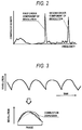
- FIG. 2 shows an example of the analytical results of the revolution behavior shown in FIG. 3 with the number of frequencies.
- the variation of revolution consists of the first order component of revolution and the second order component of revolution which is twice as many as the first order component and there are higher order components of revolution which is multiple times as many as the first order component above (not shown).
- the main order components with high intensity are the first and second order components of revolution. Accordingly, it is understood that if the dispersion of the first and second order components of revolution is quantitatively evaluated, the dispersion of combustion can be evaluated.
- FIG. 1 is the figure to show the calculation method, i.e. an embodiment by the present invention of combustion stability based on the above theory.
- the guideline values for combustion stability are calculated by programming the above calculation method in a control unit 15, based on which various compensations for desirable combustion conditions can be carried out.
- step 101 the instantaneous revolution of an engine is measured at intervals possible to detect the first and second order components of revolution.
- measurement may be carried out for every fine crank angle of an engine. That is, the program is set in the way possible to calculate CPU and also to secure the accuracy in calculation of the first and second order components of revolution.
- the cycle must be less than 1/2 (a half) of one cycle of the second order component judging from the theorem of sampling.
- step 2 a direct current component, i.e. the average revolution shall be eliminated and then the deviation from the average revolution is used for the calculation in the following.
- steps 103, 104 and 105 the first and second order components of revolution are taken out of various order components in the variation of revolution.
- the calculation method in double prime numbers is used in the following.
- the total 4 intensities i.e. each 2 intensities in both real and imaginary number parts of the first and second order components of revolution which are indicated by a trigonometric function as shown in FIG. 4 are supplied in procedure 103 corresponding to each phase at the measuring time of revolution.
- the total 4 values i.e.
- each 2 instantaneous values in both real and imaginary number parts of the specific order components of revolution such as the first and second order components can be obtained. If these instantaneous values are cumulatively totalled during one combustion in step 105, the intensities in both real and imaginary parts of the first and second order components during one combustion can be obtained. Accordingly, the vibration amplitudes, i.e. the intensities of the first and second order components can be obtained by the average of the square of each value in both real and imaginary parts in step 107. If the dispersion or deviation of vibration amplitudes is obtained from the data acquired by repeating the above in the combustion of sufficient times to make a statistical calculation in step 107, the dispersion or deviation of combustion can be acquired by a quantitative means.
- an actual programming technique may be decided to save calculation memories and to shorten calculation time.
- the output of a trigonometric function may be input into a memory as a table and in case that the calculation of a square root such as the calculation of the average of the square of each value and deviation, etc. is complicated, an intensity value may be handled as a square number and the degree of dispersion may be evaluated in variance.
- the procedure may be carried out after understanding that the guideline which is output value is nonlinear.
- first and second order components of revolution may independently be carried out only up to the calculation of intensity in one combustion and the statistical calculation of each order component of revolution may be carried out separately from that of the other order component.
- Two guidelines of combustion stability may be output or by summing up both guideline values as two variables, one guideline may be output.
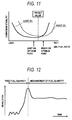
- FIG. 6 shows the characteristics of combustion in general engines, when the air/fuel ratio of fuel mixed air to be taken in is set leaner than the theory value. If air/fuel ration is set leaner by keeping both torque and revolution of an engine constant, an amount of air to be taken in increases to cause the decrease of a pumping loss and the increase of the ratio of specific heat. Accordingly, the fuel consumption is improved so that the cost of fue l is improved. On the other hand, NOx emission quantity decreases due to the drop of a combustion temperature caused by the lean ratio of air/fuel.
- the property of fuel largely affects on combustion stability mainly in the conditions before the completion of warming up of an engine.
- the volatile fuel such as light oil makes fuel injection quantity less and starting time shorter than the less-volatile fuel like heavy oil.
- an amount of fuel injection quantity required for starting an engine must be decided based on a point of compromise among mixed types of fuel.
- the volatile fuel like light oil can keep combustion stability in the leaner ratio of air/fuel than the less-volatile fuel like heavy oil.
- an amount of fuel injection quantity required for starting an engine must be decided based on a point of compromise among mixed types of fuel.
- FIG. 5 shows the general procedures of executing the compensation for combustion described above.
- step 111 whether or not the guideline conditions for combustion stability are dependable is determined. For example, when the variation of driving conditions of an engine is too great, when the detection of revolution is not accurately carried out, when sufficient data for a denominator is not obtained to make a statistical calculation and so on, a diagnosis is not performed judging that diagnosable driving conditions are not obtained.
- step 112 since the guideline for combustion stability is considered to include the conditions prior to the compensation if it is within the predetermined time after executing the compensation of combustion such as the ratio of air/fuel, etc., a diagnosis is also not performed.
- step 113 dispersion calculation value S is read out and furthermore, in step 114, dispersion compensation value L is read out to be compared with dispersion calculation value S depending on the driving conditions at that time.
- step 115 which is larger, S or L is compared and in case that S is larger, judging that the compensation for combustion is required, proceed to step 116 and count the continuous time of the judgement above with a timer T.
- timer T indicates the time longer than the predetermined time in step 117, judging that the compensation for combustion is certainly required, proceed to step 118 in which the actual compensation for combustion is carried out and then, in step 119 the compensation is completed by clearing timer T.
- the above diagnosis routine is carried out at predetermined intervals.
- the compensation for combustion substantially means to increase the ratio of air/fuel in case of lean driving, to decrease ERG rate in case of ERG rate control and the judgement of fuel type, i.e. light or heavy oil in case of the judgement of fuel property.
- the measurement accuracy of dispersion calculation value S for combustion stability depends on the accuracy of both calculation and measurement of fine revolution, i.e. input.
- the close relation is shown between combustion stability and dispersion calculation value but in case of rough revolution detection, dispersion calculation value shows the errors in combustion stability shown with slanting lines. Accordingly, corresponding to the measurement accuracy of combustion stability, the dispersion calculation value L is set higher in FIG. 5 to avoid misjudgement, the judgement time is also set longer in timer T, etc.
- the fixed fuel quantity is mainly used from the start of cranking to about the complete combustion and from hence the fuel quantity is decided by the measurement of air to be taken in. Accordingly, the fuel property obtained after the start of an engine can not directly be used for compensating the fixed fuel quantity at starting an engine. Therefore, the fuel property detected during the driving of an engine is kept in the memory which is never lost at the time of stopping an engine and based on which it is useful to compensate fuel quantity at the next start of an engine.
- the temperature of cooling water is measured at the time of starting an engine and if it is higher than the predetermined temperature, judging that the engine stops for a short time because of refueling and restarts and clearing the fuel property value, the judgement of fuel property may be repeated from the initial conditions again.
Landscapes
- Engineering & Computer Science (AREA)
- Chemical & Material Sciences (AREA)
- Combustion & Propulsion (AREA)
- General Engineering & Computer Science (AREA)
- General Physics & Mathematics (AREA)
- Mechanical Engineering (AREA)
- Physics & Mathematics (AREA)
- Combined Controls Of Internal Combustion Engines (AREA)
- Electrical Control Of Air Or Fuel Supplied To Internal-Combustion Engine (AREA)
- Feedback Control In General (AREA)
- Output Control And Ontrol Of Special Type Engine (AREA)
- Exhaust-Gas Circulating Devices (AREA)
- Electrical Control Of Ignition Timing (AREA)
Abstract
Description
- The present invention relates to an engine control unit for an internal combustion engin, and particularly relates to the fuel injector for an internal combustion engine with the control unit by which combustion conditions are detected and compensated to the predetermined conditions.
- In the prior art, for example, as shown in Japanese Patent Application Laid-Open No.4-19344, an abnormality in combustion was detected with the intensity of the predetermined frequency component to analyze the revolution of an engine with frequencies.
- The prior art above is useful to detect just one accidental abnormality in combustion but is not considered as means of detecting the stability in every combustion.
- Said problem is solved by using the structure, i.e. having a means to obtain the intensity of both the first order component of revolution for every combustion (one cycle per combustion) and the second order component of revolution which is twice as many as the first order component for every predetermined time period in the variation of revolution of an engine, means to obtain the dispersion or the deviation in the multiple intensities of both the first and second order component above during the predetermined period above and means to use the dispersion or the deviation as guidelines for combustion stability in the engine control unit with means to detect the combustion conditions of an engine based on the variation of its revolution and a means to compensate the combustion conditions above.
- By detecting the revolution of an engine, the intensities of both the first order of component of revolution in a cycle per combustion and the second order component of revolution that is twice as many as the first order component are obtained, of which dispersion or deviation is used as guidelines for combustion stability.
-
- Fig. 1 shows an embodiment in the present invention.
- Fig.2 shows the characteristics of an engine.
- Fig.3 shows the principle of the presentinvention.
- Fig.4 shows a calculation method of an embodiment in the present invention
- Fig.5 shows an embodiment in the present invention.
- Fig.6 shows the characteristics of an engine.
- Fig.7 shows the applicable objects by the present invention.
- Fig.8 shows the applicable objects by the present invention.
- Fig.9 shows the characteristics of an embodiment in the present invention
- Fig.10 shows the effect by the present invention.
- Fig.11 shows the effect by the present invention.
- Fig.12 shows the characteristics of an engine.
- Fig.13 shows an embodiment in the present invention.
- The fuel injection control unit for an internal combustion engine is described in detail on the basis of the embodiment shown in the drawing as follows.
- FIG. 8 shows an example of the engine system applied by the present invention. In this drawing, the air to be sucked up by an engine is taken through opening 2 of cleaner 1, flows through
throttle valve body 5 which accommodates a throttle valve to control the flow rate of air and flows intocollector 6. Then, air is distributed to eachinlet pipe 8 connected to each cylinder in anengine 7 and flows into cylinders. - On the other hand, fuel such as gasoline, etc. is sucked up from a
fuel tank 9, pressurized with afuel pump 10 and supplied to a fuel system in which afuel injector 13 and a fuel pressure regulator are connected with piping. Then, the fuel is pressurized to a predetermined pressure with afuel pressure regulator 14 and injected into eachinlet pipe 8 through eachfuel injection valve 13 provided for each cylinder. - Furthermore, a signal indicative of the flow rate of air is output from an
air regulator 3 and inputted into acontrol unit 15. - Furthermore, a
throttle sensor 18 to detect the opening of athrottle valve 5 is mounted on the abovethrottle valve body 5, output of which is also inputted into thecontrol unit 15. Then, a crank angle sensor is built in adistributor 16 which outputs both reference angle signal (REF) to show the position of a crank shaft in its revolution and angle signal (POS) to detect the number of revolution and these signals are also inputted into thecontrol unit 15. - An A/
F sensor 20 provided for an exhaust pipe detects the ratio of air/fuel in actual driving conditions, i.e, either rich or lean, the output signal of which is inputted into acontrol unit 15. - The main part of the
control unit 15 inputs the signals from various sensors to detect MPU, ROM and the driving conditions of an A/D converter engine as shown in FIG.7, executes the predetermined operation, outputs various control signals calculated as the results of the operation, supplies the predetermined control signals to bothfuel injector 13 anddistributor 16 and carries out the control of both fuel supply quantity and ignition timing. - In the engine as described above, the possibility to detect combustion conditions is advantageous for the achievement of the desirable combustion conditions to be described later. First of all, the detection method of combustion stability is described in the following. First, if the revolution of an engine is observed in detail, as shown in the upper part of FIG. 3, the variation of revolution of a convex curve corresponding to each explosion in each cylinder is repeated. That is, because of the output by the combustion in a certain cylinder, a crank shaft receives a positive angular velocity and then, by the compression in another cylinder it soon receives a negative angular velocity in revolution. By the balance among the above positive and negative velocities and other loads received by an engine, its average revolution is decided. Then, since the variation of revolution is caused by the combustion in an engine, it is possible to detect the dispersion of combustion if various changes of revolution are compared as shown in the lower part of FIG. 3.
- Next, the quantitative evaluation method of the dispersion above is described in the following. FIG. 2 shows an example of the analytical results of the revolution behavior shown in FIG. 3 with the number of frequencies. The variation of revolution consists of the first order component of revolution and the second order component of revolution which is twice as many as the first order component and there are higher order components of revolution which is multiple times as many as the first order component above (not shown). Among them, the main order components with high intensity are the first and second order components of revolution. Accordingly, it is understood that if the dispersion of the first and second order components of revolution is quantitatively evaluated, the dispersion of combustion can be evaluated.
- FIG. 1 is the figure to show the calculation method, i.e. an embodiment by the present invention of combustion stability based on the above theory. The guideline values for combustion stability are calculated by programming the above calculation method in a
control unit 15, based on which various compensations for desirable combustion conditions can be carried out. First, instep 101, the instantaneous revolution of an engine is measured at intervals possible to detect the first and second order components of revolution. As for the timing above, for example, measurement may be carried out for every fine crank angle of an engine. That is, the program is set in the way possible to calculate CPU and also to secure the accuracy in calculation of the first and second order components of revolution. At least, the cycle must be less than 1/2 (a half) of one cycle of the second order component judging from the theorem of sampling. Next, in step 2, a direct current component, i.e. the average revolution shall be eliminated and then the deviation from the average revolution is used for the calculation in the following. Next, insteps procedure 103 corresponding to each phase at the measuring time of revolution. By multiplying the above reference intensities by the variation of revolution instep 104 as shown in FIG. 4, the total 4 values, i.e. each 2 instantaneous values in both real and imaginary number parts of the specific order components of revolution such as the first and second order components can be obtained. If these instantaneous values are cumulatively totalled during one combustion instep 105, the intensities in both real and imaginary parts of the first and second order components during one combustion can be obtained. Accordingly, the vibration amplitudes, i.e. the intensities of the first and second order components can be obtained by the average of the square of each value in both real and imaginary parts instep 107. If the dispersion or deviation of vibration amplitudes is obtained from the data acquired by repeating the above in the combustion of sufficient times to make a statistical calculation instep 107, the dispersion or deviation of combustion can be acquired by a quantitative means. - If the above theory is used, an actual programming technique may be decided to save calculation memories and to shorten calculation time. For example, in case that the calculation of a trigonometric function is impossible or in case of complicate CPU, the output of a trigonometric function may be input into a memory as a table and in case that the calculation of a square root such as the calculation of the average of the square of each value and deviation, etc. is complicated, an intensity value may be handled as a square number and the degree of dispersion may be evaluated in variance. In this case, the procedure may be carried out after understanding that the guideline which is output value is nonlinear. Furthermore, the calculation of respective first and second order components of revolution may independently be carried out only up to the calculation of intensity in one combustion and the statistical calculation of each order component of revolution may be carried out separately from that of the other order component. Two guidelines of combustion stability may be output or by summing up both guideline values as two variables, one guideline may be output.
- Furthermore, unlike the calculation with CPU as shown in the above embodiment, in case of obtaining the desired intensity of the first and second order components as well by using the electric circuit to output the specific order component of revolution, even if the results obtained are statistically calculated, the same effect can be acquired.
- The method to achieve the desirable combustion conditions with the guideline for combustion stability obtained by the calculation above is described in the following.
- FIG. 6 shows the characteristics of combustion in general engines, when the air/fuel ratio of fuel mixed air to be taken in is set leaner than the theory value. If air/fuel ration is set leaner by keeping both torque and revolution of an engine constant, an amount of air to be taken in increases to cause the decrease of a pumping loss and the increase of the ratio of specific heat. Accordingly, the fuel consumption is improved so that the cost of fue l is improved. On the other hand, NOx emission quantity decreases due to the drop of a combustion temperature caused by the lean ratio of air/fuel. Since the ignitability of air mixed fuel decreases due to the lean ratio of air/fuel, the combustion stability which can quantitatively be controlled by the variation of torque slowly becomes unstable up to a certain ratio of air/fuel and beyond this ratio it suddenly becomes unstable due to the extreme decrease of ignitability. Like this, both combustion stability and NOx emission quantity largely depend on the ratio of air/fuel in its lean zone.
- Furthermore, there is a critical quantity for NOx exhaust allowed by the emission standard and is another critical point for combustion stability required for driving a car. Therefore, in case of driving in the lean ratio of air/fuel, it must be driven in the range not to exceed the above two critical points. Moreover, since both combustion stability and NOx emission quantity largely depend on the timing of ignition, it also must be optimized.
- Likewise, in stead of lean ratio of air/fuel, the increase of EGR rate improves the cost of fuel by the same reason as the above and since NOx emission decreases, it is desired to control an engine within the desirable range of EGR rate.
- However, the accurate control of either the ratio of air/fuel to be supplied to an engine or EGR rate is difficult due to the variation of each quality in a
fuel injector valve 13, anair regulator 3 and an EGR rate control actuator and secular deterioration, etc. so that closed loop controls are required. As one of the means of closed loop controls, the guideline for combustion stability obtained above can be used. - Furthermore, the property of fuel largely affects on combustion stability mainly in the conditions before the completion of warming up of an engine. For example, as shown in FIG. 10, when starting up an engine in the cold conditions, the volatile fuel such as light oil makes fuel injection quantity less and starting time shorter than the less-volatile fuel like heavy oil. In case that the property of mixed fuel can not be checked, an amount of fuel injection quantity required for starting an engine must be decided based on a point of compromise among mixed types of fuel. Even after starting an engine, as shown in FIG. 11, while an engine is in the cold conditions the volatile fuel like light oil can keep combustion stability in the leaner ratio of air/fuel than the less-volatile fuel like heavy oil. In this case also, when the property of mixed fuel can not be checked, an amount of fuel injection quantity required for starting an engine must be decided based on a point of compromise among mixed types of fuel.
- Therefore, If the property of fuel is judged by using the guideline for combustion stability obtained above, both fuel injection quantity at starting an engine and the ratio of air/fuel in the cold conditions can be optimized.
- FIG. 5 shows the general procedures of executing the compensation for combustion described above. First of all, in
step 111, whether or not the guideline conditions for combustion stability are dependable is determined. For example, when the variation of driving conditions of an engine is too great, when the detection of revolution is not accurately carried out, when sufficient data for a denominator is not obtained to make a statistical calculation and so on, a diagnosis is not performed judging that diagnosable driving conditions are not obtained. Next, instep 112, since the guideline for combustion stability is considered to include the conditions prior to the compensation if it is within the predetermined time after executing the compensation of combustion such as the ratio of air/fuel, etc., a diagnosis is also not performed. Then, instep 113, dispersion calculation value S is read out and furthermore, instep 114, dispersion compensation value L is read out to be compared with dispersion calculation value S depending on the driving conditions at that time. Then, instep 115, which is larger, S or L is compared and in case that S is larger, judging that the compensation for combustion is required, proceed to step 116 and count the continuous time of the judgement above with a timer T. When it is judged that the compensation for combustion is continuously required, that is, timer T indicates the time longer than the predetermined time instep 117, judging that the compensation for combustion is certainly required, proceed to step 118 in which the actual compensation for combustion is carried out and then, instep 119 the compensation is completed by clearing timer T. The above diagnosis routine is carried out at predetermined intervals. The compensation for combustion substantially means to increase the ratio of air/fuel in case of lean driving, to decrease ERG rate in case of ERG rate control and the judgement of fuel type, i.e. light or heavy oil in case of the judgement of fuel property. - In the description above, the embodiment of executing the compensation for combustion stability was shown. However, at the same time as the above, it is possible to direct the control of combustion stability toward unstability by judging that dispersion calculation value S is less than predetermined value.
- Then, the measurement accuracy of dispersion calculation value S for combustion stability depends on the accuracy of both calculation and measurement of fine revolution, i.e. input. As shown in FIG. 9, in case that the detection accuracy of revolution is high, the close relation is shown between combustion stability and dispersion calculation value but in case of rough revolution detection, dispersion calculation value shows the errors in combustion stability shown with slanting lines. Accordingly, corresponding to the measurement accuracy of combustion stability, the dispersion calculation value L is set higher in FIG. 5 to avoid misjudgement, the judgement time is also set longer in timer T, etc.
- Now, if the judgement of fuel property is described in detail, as shown in FIG. 11, since it is possible to judge the property of fuel by measuring the combustion stability at the predetermined ratio of air/fuel in the cold conditions, the rate of heavy oil in fuel can quantitatively be obtained with dispersion calculation value S at the reference ratio of air/fuel. Furthermore, in case that any disturbance largely affects on the detection accuracy of fuel property, not to judge fuel just by one measurement but there is the method to increase the rate of heavy oil by the predetermined value in every measurement and to approach to the real value little by little. Based on the fuel property quantitativly obtained in the way such as the above, as shown in FIG. 13, both fuel correction factor at a low water temperature and fixed fuel quantity at starting an engine may be decided. These control factors, as shown in FIG. 12, are used at the time of starting an engine. That is, the fixed fuel quantity is mainly used from the start of cranking to about the complete combustion and from hence the fuel quantity is decided by the measurement of air to be taken in. Accordingly, the fuel property obtained after the start of an engine can not directly be used for compensating the fixed fuel quantity at starting an engine. Therefore, the fuel property detected during the driving of an engine is kept in the memory which is never lost at the time of stopping an engine and based on which it is useful to compensate fuel quantity at the next start of an engine. Moreover, in case that the above mechanism can not be set, as a simple method the temperature of cooling water is measured at the time of starting an engine and if it is higher than the predetermined temperature, judging that the engine stops for a short time because of refueling and restarts and clearing the fuel property value, the judgement of fuel property may be repeated from the initial conditions again.
- In the above description, regardless of number of cylinders in an engine, the embodiment of evaluating the average combustion conditions of all cylinders was shown. However, if the variation of angular velocity of revolution in the combustion process in respective cylinders is independently analyzed, the combustion conditions in each cylinder can be obtained so that the independent compensation for each cylinder can be carried out.
- By the present invention, it is possible to detect the combustion conditions in an engine and to correct them to desirable conditions.
Claims (7)
- An engine control unit with the characteristics, i.e. having means to obtain the intensity of both the first order component of revolution for every combustion (one cycle per combustion) and the second order component of revolution which is twice as many as the first order component for every predetermined time period in the variation of revolution of an engine, means to obtain the dispersion or the deviation in the multiple intensities of both the first and second order components above during the predetermined period above and means to use the dispersion or the deviation above means to detect the combustion conditions of an engine based on the variation of its revolution and means to compensate the combustion conditions above.
- In claim 1, an engine control unit with the characteristics, i.e. having means to obtain the dispersion or the deviation in the total of intensities of both the first and second order components of revolution above.
- In claim 1, an engine control unit with the characteristics, i.e. having means to independently obtain the dispersion or the deviation in the intensities of both the first and second order components of revolution above.
- In claim 1, an engine control unit with the characteristics, i.e. having means to compensate one at least among the ratio of air/fuel supplied to an engine, EGR rate, fuel injection quantity at starting, increase of fuel at low water temperature and ignition timing based on the value of dispersion or deviation above.
- In claim 4, an engine control unit with the of dispersion or deviation above, characteristics, i.e. having means to keep the memory of compensation quantity for the fuel supplied at starting of an engine even at the time of engine stop.
- in laim 5, an engine control unit with the characteristics, i.e, having means to keep the memory of ompensation quantity for the fuel supplied at the time of starting an engine even when an engine stops, means to detect the operation of a fuel feeder during the engine stop, means to detect the increase of residual fuel from the predetermined quantity before and after an engine stops, means to detect the water temperature equal to or higher than the predetermined value at the time of starting an engine and means to eliminate the memory above when at least one of the conditions detected above is established.
- In claim 1, an engine control unit with the characteristics, i.e. having means to obtain the dispersion or the deviation above for each cylinder.
Applications Claiming Priority (2)
| Application Number | Priority Date | Filing Date | Title |
|---|---|---|---|
| JP7030392A JPH08218917A (en) | 1995-02-20 | 1995-02-20 | Engine control device |
| JP30392/95 | 1995-02-20 |
Publications (2)
| Publication Number | Publication Date |
|---|---|
| EP0727652A2 true EP0727652A2 (en) | 1996-08-21 |
| EP0727652A3 EP0727652A3 (en) | 1998-01-07 |
Family
ID=12302657
Family Applications (1)
| Application Number | Title | Priority Date | Filing Date |
|---|---|---|---|
| EP96102541A Withdrawn EP0727652A3 (en) | 1995-02-20 | 1996-02-20 | Engine control unit for an internal combustion engine |
Country Status (4)
| Country | Link |
|---|---|
| US (1) | US5678520A (en) |
| EP (1) | EP0727652A3 (en) |
| JP (1) | JPH08218917A (en) |
| KR (1) | KR960031772A (en) |
Cited By (1)
| Publication number | Priority date | Publication date | Assignee | Title |
|---|---|---|---|---|
| US8387449B2 (en) | 2007-04-13 | 2013-03-05 | Christian Engström | Method and device for testing of a combustion engine or an associated structure and a rig |
Families Citing this family (9)
| Publication number | Priority date | Publication date | Assignee | Title |
|---|---|---|---|---|
| SE512556C2 (en) * | 1995-12-22 | 2000-04-03 | Volvo Ab | Method for reducing vibration in a vehicle and device for carrying out the method |
| SE519192C2 (en) * | 2000-05-17 | 2003-01-28 | Mecel Ab | Engine control method |
| US20040203621A1 (en) * | 2002-10-23 | 2004-10-14 | International Business Machines Corporation | System and method for queuing and bookmarking tekephony conversations |
| US7292933B2 (en) * | 2004-11-15 | 2007-11-06 | Lotus Engineering, Inc. | Engine misfire detection |
| JP4735497B2 (en) * | 2006-09-27 | 2011-07-27 | トヨタ自動車株式会社 | Fuel cetane number discrimination system for compression ignition type internal combustion engine |
| JP4927697B2 (en) * | 2007-12-20 | 2012-05-09 | 株式会社豊田中央研究所 | Fuel property estimation device for internal combustion engine |
| JP4799645B2 (en) * | 2009-07-02 | 2011-10-26 | 三菱電機株式会社 | Control device for internal combustion engine |
| JP5549510B2 (en) * | 2010-09-30 | 2014-07-16 | マツダ株式会社 | Lean burn engine |
| JP5987814B2 (en) * | 2013-11-18 | 2016-09-07 | トヨタ自動車株式会社 | Control device for internal combustion engine for vehicle |
Citations (4)
| Publication number | Priority date | Publication date | Assignee | Title |
|---|---|---|---|---|
| US4357662A (en) * | 1978-05-08 | 1982-11-02 | The Bendix Corporation | Closed loop timing and fuel distribution controls |
| US5200899A (en) * | 1990-04-20 | 1993-04-06 | Regents Of The University Of Michigan | Method and system for detecting the misfire of an internal combustion engine utilizing angular velocity fluctuations |
| US5303158A (en) * | 1990-05-14 | 1994-04-12 | Honda Giken Kogyo Kabushiki Kaisha | Misfire-detecting system for an internal combustion engine |
| EP0637738A1 (en) * | 1993-08-04 | 1995-02-08 | CENTRO RICERCHE FIAT Società Consortile per Azioni | A process and system for detecting misfiring in internal combustion engines |
Family Cites Families (4)
| Publication number | Priority date | Publication date | Assignee | Title |
|---|---|---|---|---|
| DE4414727B4 (en) * | 1993-04-27 | 2004-01-29 | Hitachi, Ltd. | Control method and control unit for multi-cylinder internal combustion engines |
| US5559705A (en) * | 1995-02-03 | 1996-09-24 | Motorola, Inc. | Adaptive profile correction for rotating position encoders in reciprocating engines |
| US5587524A (en) * | 1995-05-03 | 1996-12-24 | Ford Motor Company | Misfire detection assembly |
| US5602331A (en) * | 1995-06-06 | 1997-02-11 | Chrysler Corporation | Engine misfire detection with cascade filter configuration |
-
1995
- 1995-02-20 JP JP7030392A patent/JPH08218917A/en active Pending
-
1996
- 1996-02-16 KR KR1019960003832A patent/KR960031772A/en not_active Application Discontinuation
- 1996-02-20 EP EP96102541A patent/EP0727652A3/en not_active Withdrawn
- 1996-02-20 US US08/603,343 patent/US5678520A/en not_active Expired - Fee Related
Patent Citations (4)
| Publication number | Priority date | Publication date | Assignee | Title |
|---|---|---|---|---|
| US4357662A (en) * | 1978-05-08 | 1982-11-02 | The Bendix Corporation | Closed loop timing and fuel distribution controls |
| US5200899A (en) * | 1990-04-20 | 1993-04-06 | Regents Of The University Of Michigan | Method and system for detecting the misfire of an internal combustion engine utilizing angular velocity fluctuations |
| US5303158A (en) * | 1990-05-14 | 1994-04-12 | Honda Giken Kogyo Kabushiki Kaisha | Misfire-detecting system for an internal combustion engine |
| EP0637738A1 (en) * | 1993-08-04 | 1995-02-08 | CENTRO RICERCHE FIAT Società Consortile per Azioni | A process and system for detecting misfiring in internal combustion engines |
Cited By (1)
| Publication number | Priority date | Publication date | Assignee | Title |
|---|---|---|---|---|
| US8387449B2 (en) | 2007-04-13 | 2013-03-05 | Christian Engström | Method and device for testing of a combustion engine or an associated structure and a rig |
Also Published As
| Publication number | Publication date |
|---|---|
| JPH08218917A (en) | 1996-08-27 |
| US5678520A (en) | 1997-10-21 |
| KR960031772A (en) | 1996-09-17 |
| EP0727652A3 (en) | 1998-01-07 |
Similar Documents
| Publication | Publication Date | Title |
|---|---|---|
| US5131372A (en) | Apparatus for controlling the respective cylinders in the fuel supply system of an internal combustion engine | |
| US5533332A (en) | Method and apparatus for self diagnosis of an internal combustion engine | |
| US6273064B1 (en) | Controller and control method for an internal combustion engine using an engine-mounted accelerometer | |
| US6546912B2 (en) | On-line individual fuel injector diagnostics from instantaneous engine speed measurements | |
| US6012438A (en) | System for checking a pressure sensor of a fuel supply system for an internal combustion engine | |
| US5568725A (en) | Apparatus and method for controlling the air-fuel ratio of an internal combustion engine | |
| US20060260593A1 (en) | Air/fuel imbalance detection system and method | |
| US4467770A (en) | Method and apparatus for controlling the air-fuel ratio in an internal combustion engine | |
| US20090064967A1 (en) | Control for an internal-combustion engine | |
| EP0651150A2 (en) | Fuel injection apparatus for engine | |
| US11112333B2 (en) | Sensor failure diagnostic apparatus | |
| US9010303B2 (en) | System and method of detecting hydraulic start-of-injection | |
| US5126943A (en) | Learning-correcting method and apparatus and self-diagnosis method and apparatus in fuel supply control system of internal combustion engine | |
| CN102325985B (en) | Control device for internal combustion engine | |
| US5950598A (en) | Method for determining the injection time for a direct-injection internal combustion engine | |
| KR0166978B1 (en) | Method of electronic engine control for internal combustion engine having a plurality of cylinders | |
| EP0727652A2 (en) | Engine control unit for an internal combustion engine | |
| US4911133A (en) | Fuel injection control system of automotive engine | |
| US20020007670A1 (en) | Engine torque-detecting method and an apparatus therefore | |
| US20010003919A1 (en) | Method for diagnosing an exhaust-gas recirculation system of an internal combustion engine | |
| CN108350826B (en) | Control device for internal combustion engine | |
| US5033437A (en) | Method of controlling air-fuel ratio for use in internal combustion engine and apparatus of controlling the same | |
| US9328685B2 (en) | Inter-cylinder air-fuel ratio variation abnormality detection apparatus for multicylinder internal combustion engine | |
| US5728932A (en) | Method for diagnosing performance of intake air amount detection device and apparatus thereof | |
| US6871135B2 (en) | Method for operating an internal combustion engine, the internal combustion engine and a control apparatus therefor |
Legal Events
| Date | Code | Title | Description |
|---|---|---|---|
| PUAI | Public reference made under article 153(3) epc to a published international application that has entered the european phase |
Free format text: ORIGINAL CODE: 0009012 |
|
| 17P | Request for examination filed |
Effective date: 19960220 |
|
| AK | Designated contracting states |
Kind code of ref document: A2 Designated state(s): DE FR GB |
|
| PUAL | Search report despatched |
Free format text: ORIGINAL CODE: 0009013 |
|
| AK | Designated contracting states |
Kind code of ref document: A3 Designated state(s): DE FR GB |
|
| 17Q | First examination report despatched |
Effective date: 20000717 |
|
| GRAG | Despatch of communication of intention to grant |
Free format text: ORIGINAL CODE: EPIDOS AGRA |
|
| GRAG | Despatch of communication of intention to grant |
Free format text: ORIGINAL CODE: EPIDOS AGRA |
|
| GRAH | Despatch of communication of intention to grant a patent |
Free format text: ORIGINAL CODE: EPIDOS IGRA |
|
| STAA | Information on the status of an ep patent application or granted ep patent |
Free format text: STATUS: THE APPLICATION IS DEEMED TO BE WITHDRAWN |
|
| 18D | Application deemed to be withdrawn |
Effective date: 20020727 |