EP0727609B1 - Dampferzeugungssystem - Google Patents
Dampferzeugungssystem Download PDFInfo
- Publication number
- EP0727609B1 EP0727609B1 EP19960301047 EP96301047A EP0727609B1 EP 0727609 B1 EP0727609 B1 EP 0727609B1 EP 19960301047 EP19960301047 EP 19960301047 EP 96301047 A EP96301047 A EP 96301047A EP 0727609 B1 EP0727609 B1 EP 0727609B1
- Authority
- EP
- European Patent Office
- Prior art keywords
- steam
- flow
- boiler
- temperature
- water
- Prior art date
- Legal status (The legal status is an assumption and is not a legal conclusion. Google has not performed a legal analysis and makes no representation as to the accuracy of the status listed.)
- Expired - Lifetime
Links
- XLYOFNOQVPJJNP-UHFFFAOYSA-N water Substances O XLYOFNOQVPJJNP-UHFFFAOYSA-N 0.000 claims abstract description 38
- 238000009835 boiling Methods 0.000 claims description 8
- 238000010276 construction Methods 0.000 claims description 8
- 238000012544 monitoring process Methods 0.000 claims description 7
- 238000011144 upstream manufacturing Methods 0.000 claims description 3
- 230000001419 dependent effect Effects 0.000 claims description 2
- 238000000034 method Methods 0.000 claims description 2
- 239000012530 fluid Substances 0.000 description 7
- 238000004891 communication Methods 0.000 description 3
- 238000012986 modification Methods 0.000 description 2
- 230000004048 modification Effects 0.000 description 2
- 230000002159 abnormal effect Effects 0.000 description 1
- 239000000567 combustion gas Substances 0.000 description 1
- 238000010586 diagram Methods 0.000 description 1
- 238000005259 measurement Methods 0.000 description 1
- 230000025508 response to water Effects 0.000 description 1
Images
Classifications
-
- F—MECHANICAL ENGINEERING; LIGHTING; HEATING; WEAPONS; BLASTING
- F22—STEAM GENERATION
- F22D—PREHEATING, OR ACCUMULATING PREHEATED, FEED-WATER FOR STEAM GENERATION; FEED-WATER SUPPLY FOR STEAM GENERATION; CONTROLLING WATER LEVEL FOR STEAM GENERATION; AUXILIARY DEVICES FOR PROMOTING WATER CIRCULATION WITHIN STEAM BOILERS
- F22D5/00—Controlling water feed or water level; Automatic water feeding or water-level regulators
- F22D5/26—Automatic feed-control systems
-
- Y—GENERAL TAGGING OF NEW TECHNOLOGICAL DEVELOPMENTS; GENERAL TAGGING OF CROSS-SECTIONAL TECHNOLOGIES SPANNING OVER SEVERAL SECTIONS OF THE IPC; TECHNICAL SUBJECTS COVERED BY FORMER USPC CROSS-REFERENCE ART COLLECTIONS [XRACs] AND DIGESTS
- Y10—TECHNICAL SUBJECTS COVERED BY FORMER USPC
- Y10T—TECHNICAL SUBJECTS COVERED BY FORMER US CLASSIFICATION
- Y10T137/00—Fluid handling
- Y10T137/8593—Systems
- Y10T137/87265—Dividing into parallel flow paths with recombining
- Y10T137/87507—Electrical actuator
Definitions
- the present invention relates to a steam-raising system
- a boiler having (a) a passageway for water and/or steam, (b) an inlet to the passageway through which water is introduced continuously for given periods when the boiler is in use, (c) a heater to heat the passageway and (d) an outlet from the passageway from which steam emerges continuously as water is introduced through the inlet, the system further comprising a pump connected by a flow-path to the said inlet to pump water thereto along the said flow-path, and flow-control means in the said flow-path, in which the flow-control means comprise a plurality of lines which constitute a part of the flow-path, which are connected between the pump and the boiler in parallel with one another, and which are independently openable to enable the amount of water delivered to the boiler to be varied.
- US-A-1558997 describes such steam-raising system as referred to in the opening paragraph of the present specification.
- the flow through the conduit is controlled, under normal pressure conditions, solely in response to water level in the boiler, and the flow control is modified for controlling the flow through the conduit under abnormal conditions solely by pressure in the boiler.
- WO 88/04390 describes a steam-raising system comprising a distributor block from which extends a number of lines from each of which extends a return line to a boiler feed tank which is located upstream of the pump. According to the amount of water returned to the feed-tank via the distributor block and the return line, a variable amount of water can be fed to the boiler in this prior construction.
- a disadvantage of such a construction is the loss of energy when the flow path of water is switched to the feed tank.
- the present invention seeks to reduce this.
- the present invention is directed to a steam-raising system having the construction set out in the opening paragraph of the present specification, in which the flow-control means comprise a plurality of lines which constitute a part of the flow-path, which are connected between the pump and boiler in parallel with one another, and which are independently openable to enable the amount of water delivered to the boiler to be varied, in which the flow control means comprise a shut-off valve and a flow regulator which maintains a constant flow through it substantially independently of the pressures upstream of its inlet and downstream of its outlet.
- the flow regulator may comprise a piston valve the inlet port of which has a variable opening which is dependent upon the relative position of the piston in the valve.
- the flow through the regulator may be through a fixed orifice across which a fixed pressure differential is maintained by means of the piston-valve. This may be achieved by means of resilient means acting on the piston, the force of which determines the pressure differential across the orifice.
- a first one of the lines and also the construction of the boiler may be such that the flow rate allowed through that one of the lines when it is in the open condition, with the other lines in the closed condition, produces superheated steam at a given temperature in excess of the normal boiling temperature of water at the steam output pressure of the system.
- Temperature monitoring means may be provided downstream of the boiler to measure the temperature of the steam output of the boiler.
- the temperature monitoring means may be connected to a control unit of the system which causes one of the said lines to open at a first temperature of superheated steam.
- the control unit may be further connected to open a further one of the said lines when the temperature indicated by the temperature monitoring exceeds a second temperature of superheated steam which is higher than the said first temperature of superheated steam.
- the control unit may thereby maintain a given flow rate or a given head of steam output.
- the control unit may be such as to close a given one of the said lines at a predetermined temperature below that at which it opens that line, to provide a hysteresis range between the closing and opening temperatures.
- the said first temperature of super heated steam may be substantially 5° Centigrade above boiling point of water at the pressure of the steam provided by the system.
- the said second temperature of superheated steam may be substantially 10° Centigrade above that boiling point.
- the hysteresis range may be substantially 1° Centigrade.
- the present invention extends to a method of raising steam by a system in accordance with the present invention.
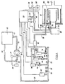
- the system shown in Figure 1 comprises a boiler feed tank 10 having an outlet 12 which is connected to the input of a pump 14 via a passageway 16.
- the output 18 from the pump 14 is connected via a further passageway 20 to a gallery 22.
- a pump discharge pressure gauge 24 Also connected to the output 18 of the pump 14 is a pump discharge pressure gauge 24 and a manually adjustable valve 26.
- the valve 26 is such as to maintain the discharge pressure of the pump at a substantially constant preset value. This value is normally 28 Bar as read from the gauge 24. The valve 26 maintains this value by returning water to the boiler feed tank 10 via the return passageway 30, as necessary.
- Three flow lines 32, 34, and 36 extend from the gallery 22 to a common feed passageway 38 for the delivery of water from the pump feed tank 10 via the passageway 16 and 20 and the gallery 22, to a water inlet 40 of a boiler 42.
- a steam outlet 44 from the boiler 42 is connected to a header 46 via a steam passageway 48.
- the header 46 is hollow and is generally T-shaped with the T on its side so that the part of the header corresponding to what is normally upright in the letter T is horizontal.
- the passageway 48 is connected at its end further from the steam outlet 44 to the base of the T of the header 46.
- Two pressure switches 50 and 52 are connected to the header 46 so as to be exposed to the pressure therewithin.
- the header 40 is also provided with a pressure safety valve 54 above the main steam outlet 56 of the header 46, and a header drain valve 58.
- a temperature sensor 60 is also provided on the passageway 48 as monitoring means to provide a measurement of the temperature of the steam from the boiler 42.
- each flow line 32, 34, and 36 there are arranged respective solenoid-operated shut-off valves 64, 66 and 68 operated by solenoids 70, 72 and 74. Respectively connected in series with the shut-off valves 64, 66, and 68 are flow regulators 76, 78 and 80.
- the flow lines 32, 34, and 36 are all connected downstream of the flow regulators 76, 78 and 80 to a common flowmeter 82 from the output of which extends the passageway 38.
- a further pressure safety cut-out switch 62 is connected to the gallery 22 so as to be exposed to the pressure thereof.
- Outputs from the switches 50, 52 and 62 along with the output from the temperature sensor 60 are all electrically connected to respective inputs of a control unit 84. Outputs therefrom are respectively connected to the solenoids 70, 72, and 74.
- the control unit 84 also has an output connected to the flowmeter 82, and a burner shut-off 83. If the flowrate of water is measured by the flowmeter 82 falls below a predetermined limit, for example 1 litre/min, the control unit will shut off the burner 83.
- the boiler 42 comprises a multi-helical tubular conduit 86 which meanders within the interior of the boiler 42.
- the burner 88 of the boiler 42 directs a flame within the helices of the tubular conduit 86 to heat up the water and/or steam therewithin.
- the boiler 42 is also provided with a flue 90 for the escape of the combustion gases from the burner 88.
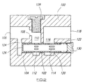
- Figure 2 shows one possible construction. It comprises a piston valve block 100 formed with a cylinder 102 within which a hollow piston 104 is slidable axially. An inlet 106 into the regulator extends axially and inwardly therein, to an orifice 108 between the inlet 106 and a transversely extending bore 110 which opens into the cylinder 102.
- the piston 104 is provided with slots 112, which put the piston interior into communication with the bore 110.
- the piston 104 is also provided with further slots 114 downstream of the slots 112, and these put the piston interior into communication with a further transverse bore 116 connected to an axially extending outlet 118.
- the slots 114 are adjacent to a shoulder 120 of the block 100. Movement of the piston 104 in a downstream direction causes the shoulder 120 to cut off increasing proportions of the slots 114, so as to reduce the area of those slots which is available for fluid to pass from the piston interior to the bore 116. Such movement of the piston 104 is resisted by a spring 122 within the block 100.
- a further transverse bore 124 is provided by which the inlet 106 is in direct communication with a blind end 126 of the piston 104 further from the spring 122.
- the effective size of the orifice 108 is adjustable by means of a screw 128 which engages a screwthreaded portion of the block 100 where it defines the bore 110.
- the force exerted by the spring 122 on the piston 104 can be adjusted by means of a screw 130 which engages a screwthreaded portion of the block 100 where it defines an outer end of the cylinder 102.
- the pump 14 feeds water from the boiler feed tank 10 to the boiler 42 via the passageways 16 and 20, the gallery 22, the lines 32 and/or 34 and/or 36, and the passageway 38.
- the boiler 42 heats the water which passes through a helical conduit 86 so that the water becomes superheated steam by the time it exits the outlet 44 from the boiler 42. This superheated steam is then available at the outlet 56 from the header 46 to which the steam is fed from the boiler 42 via the passageway 48.
- control unit 84 opens only the solenoid-operated shut-off valve 64 so that water is fed at a constant rate through the flow regulator 76 to the passageway 38 and thence to the inlet 40 of the boiler 42.
- the flow regulator 76 maintains a constant flow at a rate which, for the given specification of the burner 88, produces superheated steam at the outlet 44 and consequently in the passageway 48 and at the header 46.
- the control unit 84 switches open the solenoid-operated shut-off valve 66 to enable an additional amount of water to be fed to the boiler 42 via the flowmeter 82 and the passageway 38 at a rate determined by the flow regulator 78.
- the control unit 84 opens the solenoid operated shut-off valve 68 to cause a further amount of water to flow into the passageway 38 via the flowmeter 82, at a flow rate determined by the flow regulator 80.
- shut-off valves are closed by the control unit 84.
- Such control enables superheated steam to be provided by the boiler at a given temperature, with a substantially constant pressure.
- the control unit 84 switches off the burner 88 at the switch 83. It also switches off the pump 14 and closes the shut-off valves 64, 66 and 68. Once the pressure indicated by the pressure switch 50 falls below the predetermined amount, the system is switched back on by the turning on of the pump 14, the opening of the valve 64, and the switching on of the burner 88 at the burner switch 83. There may be a hysteresis range between the pressure at which shut-down occurs and the pressure at which the system is switched back on.
- control unit 84 will also shut the system down as a safety measure by switching off the pump 14 and the burner 88 and also by closing the valves 64, 66 and 68.
- control unit 84 will shut the system down as a safety measure.
- the flow regulators 76, 78 and 80 may each comprise a Kates® Mini-FloTM or a Kates® Fix-a-FloTM regulator made by W.A. Kates® Company of 1450 Jarvis Avenue, Ferndale, Michigan 48220, United States of America and distributed in the United Kingdom by Fluid Controls Limited of Minerva House, Calleva Park, Aldermaston, Berkshire, RG7 4QW, England.
- Two further sets 94 and 96 of three lines each for two further boilers may extend from the gallery 22, these lines being blanked off in the system illustrated in Figure 1.
- the temperature sensor 60 may comprise two temperature sensors, one for regulation and one for safety shut-down.
Landscapes
- Engineering & Computer Science (AREA)
- Physics & Mathematics (AREA)
- Thermal Sciences (AREA)
- Mechanical Engineering (AREA)
- General Engineering & Computer Science (AREA)
- Control Of Steam Boilers And Waste-Gas Boilers (AREA)
- Hydrogen, Water And Hydrids (AREA)
- Vaporization, Distillation, Condensation, Sublimation, And Cold Traps (AREA)
Claims (14)
- Dampferzeugungssystem mit einem Kessel (42), der (a) eine Leitung (86) für Wasser und/oder Dampf, (b) einen Einlaß (40) für die Leitung (86), durch den über bestimmte Zeiträume während des Betriebs des Kessels (42) kontinuierlich Wasser eingeleitet wird, (c) einen Erhitzer (88) zum Erhitzen der Leitung (86) und (d) einen Auslaß (44) der Leitung (86) aufweist, aus dem während des Einlassens von Wasser durch den Einlaß (40) kontinuierlich Dampf austritt, sowie mit einer Pumpe (14), die über eine mit Strömungskontrollorganen (32, 34, 36, 64, 66, 68, 76, 78, 80) versehene Strömungskanalanordnung (18, 20, 22, 32, 34, 36, 38) mit dem Einlaß (40) verbunden ist, um über diese Strömungskanalanordnung (18, 20, 22, 32, 34, 36, 38) Wasser zu ihm zu pumpen, wobei die Strömungskontrollorgane (32, 34, 36, 64, 66, 68, 76, 78, 80) mehrere, Teile der Strömungskanalanordnung (18, 20, 22, 32, 34, 36, 38) bildende Leitungen (32, 34, 36) umfassen, welche parallel zueinander zwischen der Pumpe (14) und dem Kessel (42) angeordnet sind und welche sich unabhängig voneinander öffnen lassen, um die dem Kessel (42) zugeführte Wassermenge verändern zu können, dadurch gekennzeichnet, daß die Strömungskontrollorgane ein Schließventil (64) und einen Stömungsregler (76) umfassen, der im wesentlichen unabhängig von den vor seinem Einlaß (106) und hinter seinem Auslaß (118) herrschenden Drücken eine konstante Strömung aufrechterhält.
- Dampferzeugungssystem nach Anspruch 1, dadurch gekennzeichnet, daß das Schließventil (64) als Magnetventil (64) ausgebildet ist.
- Dampferzeugungssystem nach Anspruch 1 oder 2, dadurch gekennzeichnet, daß der Strömungsregler (76) ein Kolbenventil aufweist, dessen Einlaßkanal (110, 112) eine von der Position seines Kolbens (104) abhängige, veränderliche Öffnung besitzt.
- Dampferzeugungssystem nach Anspruch 3, dadurch gekennzeichnet, daß die Strömung durch den Strömungsregler (76) eine eingestellte Öffnung (108, 128) passiert, an der durch das Kolbenventil eine bestimmte Druckdifferenz aufrechterhalten wird.
- Dampferzeugungssystem nach Anspruch 4, dadurch gekennzeichnet, daß die festgelegte Druckdifferenz unter Zuhilfenahme eines auf den Kolben (104) einwirkenden Federorganes (122) aufrechterhalten wird, dessen Kraft die Druckdifferenz an der Öffnung (108, 128) bestimmt.
- Dampferzeugungssystem nach einem der vorherigen Ansprüche, dadurch gekennzeichnet, daß eine erste Leitung (32) und der Kessel (42) so ausgelegt sind, daß die diese Leitung (32) in ihrem geöffneten Zustand, bei geschlossenen übrigen Leitungen (34, 36) passierende Strömung zur Erzeugung von überhitztem Dampf mit einer Temperatur oberhalb der normalen Siedetemperatur von Wasser beim Dampfauslaßdruck des Systems führt.
- Dampferzeugungssystem nach einem der vorherigen Ansprüche, dadurch gekennzeichnet, daß stromabwärts des Kessels (42) ein Temperaturüberwachungsorgan (60) vorgesehen ist, das die Temperatur des aus dem Kessel (42) austretenden Dampfes mißt.
- Dampferzeugungssystem nach Anspruch 7, dadurch gekennzeichnet, daß das Temperaturüberwachungsorgan (60) mit einer Steuereinheit (84) des Systems verbunden ist, die bei einer ersten Temperatur des erhitzten Dampfes das Öffnen einer (32) der Leitungen (32, 34, 36) bewirkt.
- Dampferzeugungssystem nach Anspruch 8, dadurch gekennzeichnet, daß die Steuereinheit (84) das Öffnen einer weiteren Leitung (34) der Leitungen (32, 34, 36) bewirkt, sobald die vom Temperaturüberwachungsorgan (60) ermittelte Temperatur eine zweite Temperatur des überhitzten Dampfes übersteigt, die höher ist als die bereits genannte erste Temperatur des überhitzten Dampfes, wodurch die Steuereinheit (84) eine bestimmte Strömungsrate oder eine bestimmte Höchstmenge austretenden Dampfes aufrechterhält.
- Dampferzeugungssystem nach Anspruch 9, dadurch gekennzeichnet, daß die erste Temperatur des überhitzten Dampfes im wesentlichen 5 °C höher ist als der Siedepunkt des Wassers bei dem im System herrschenden Dampfdruck.
- Dampferzeugungssystem nach Anspruch 9, dadurch gekennzeichnet, daß die zweite Temperatur des überhitzten Dampfes im wesentlichen 10 °C höher ist als der Siedepunkt des Wassers bei dem im System herrschenden Dampfdruck.
- Dampferzeugungssystem nach einem der Ansprüche 8 bis 11, dadurch gekennzeichnet, daß die Steuereinheit (84) so ausgebildet ist, daß sie eine (34) der Leitungen (32, 34, 36) bei einer Temperatur schließt, die niedriger als die Temperatur ist, bei der sie diese Leitung (34) öffnet, um einen Hysteresebereich zwischen den Schließ- und Öffnungstemperaturen zu erzeugen.
- Dampferzeugungssystem nach Anspruch 12, dadurch gekennzeichnet, daß der Hysteresebereich etwa 1 °C beträgt.
- Verfahren zur Dampferzeugung unter Verwendung eines der in den Ansprüchen 1 bis 13 beanspruchten Systeme.
Applications Claiming Priority (2)
| Application Number | Priority Date | Filing Date | Title |
|---|---|---|---|
| GB9503076 | 1995-02-16 | ||
| GB9503076A GB9503076D0 (en) | 1995-02-16 | 1995-02-16 | A steam-raising system |
Publications (2)
| Publication Number | Publication Date |
|---|---|
| EP0727609A1 EP0727609A1 (de) | 1996-08-21 |
| EP0727609B1 true EP0727609B1 (de) | 2000-12-13 |
Family
ID=10769737
Family Applications (1)
| Application Number | Title | Priority Date | Filing Date |
|---|---|---|---|
| EP19960301047 Expired - Lifetime EP0727609B1 (de) | 1995-02-16 | 1996-02-15 | Dampferzeugungssystem |
Country Status (5)
| Country | Link |
|---|---|
| US (1) | US5850809A (de) |
| EP (1) | EP0727609B1 (de) |
| AT (1) | ATE198101T1 (de) |
| DE (1) | DE69611195T2 (de) |
| GB (1) | GB9503076D0 (de) |
Families Citing this family (3)
| Publication number | Priority date | Publication date | Assignee | Title |
|---|---|---|---|---|
| GB9923786D0 (en) | 1999-10-08 | 1999-12-08 | Eaton Williams Group Ltd | A steam-raising system |
| US20110300050A1 (en) * | 2010-06-08 | 2011-12-08 | Memc Electronic Materials, Inc. | Trichlorosilane Vaporization System |
| US20160169451A1 (en) * | 2014-12-12 | 2016-06-16 | Fccl Partnership | Process and system for delivering steam |
Family Cites Families (13)
| Publication number | Priority date | Publication date | Assignee | Title |
|---|---|---|---|---|
| US1558997A (en) * | 1923-06-19 | 1925-10-27 | Munzinger Friedrich | Method and means for controlling the water level in steam boilers |
| US3135282A (en) * | 1961-10-20 | 1964-06-02 | Fmc Corp | Pressure control for water systems |
| US3357359A (en) * | 1965-07-19 | 1967-12-12 | Syncroflo Inc | Combination fire and domestic water system |
| US3612005A (en) * | 1970-01-12 | 1971-10-12 | Foster Wheeler Corp | Once-through steam generator recirculating startup system |
| US3759141A (en) * | 1971-12-27 | 1973-09-18 | J Zibrun | Steam engine |
| US3879616A (en) * | 1973-09-17 | 1975-04-22 | Gen Electric | Combined steam turbine and gas turbine power plant control system |
| US4036011A (en) * | 1976-01-28 | 1977-07-19 | Westinghouse Electric Corporation | Multiple valve sequential control for a combined cycle power plant |
| US4019467A (en) * | 1976-04-20 | 1977-04-26 | Westinghouse Electric Corporation | Valve sequencing startup control system for once-through boiler |
| DE2804045A1 (de) * | 1978-01-31 | 1979-08-09 | Bosch Gmbh Robert | Steuervorrichtung fuer einen hydraulisch betriebenen verbraucher |
| US4644967A (en) * | 1983-11-25 | 1987-02-24 | Vapor Energy Corp. | Fluid flow control system |
| GB8629644D0 (en) * | 1986-12-11 | 1987-01-21 | Cubit Mfg Ltd | Flash boiler control apparatus |
| US4759314A (en) * | 1987-12-14 | 1988-07-26 | The Babcock & Wilcox Company | Method of control of steam quality from a steam generator |
| GB8906200D0 (en) * | 1989-03-17 | 1989-05-04 | Cubit Ltd | Heat exchanger |
-
1995
- 1995-02-16 GB GB9503076A patent/GB9503076D0/en active Pending
-
1996
- 1996-02-14 US US08/601,440 patent/US5850809A/en not_active Expired - Lifetime
- 1996-02-15 DE DE69611195T patent/DE69611195T2/de not_active Expired - Fee Related
- 1996-02-15 AT AT96301047T patent/ATE198101T1/de not_active IP Right Cessation
- 1996-02-15 EP EP19960301047 patent/EP0727609B1/de not_active Expired - Lifetime
Also Published As
| Publication number | Publication date |
|---|---|
| EP0727609A1 (de) | 1996-08-21 |
| DE69611195T2 (de) | 2001-07-19 |
| GB9503076D0 (en) | 1995-04-05 |
| ATE198101T1 (de) | 2000-12-15 |
| DE69611195D1 (de) | 2001-01-18 |
| US5850809A (en) | 1998-12-22 |
Similar Documents
| Publication | Publication Date | Title |
|---|---|---|
| US6418956B1 (en) | Pressure controller | |
| US4340355A (en) | Furnace control using induced draft blower, exhaust gas flow rate sensing and density compensation | |
| US5458294A (en) | Control system for controlling gas fuel flow | |
| NL1013665C2 (nl) | Hydraulische stabilisator inrichting bestemd voor een verwarmingsinrichting. | |
| US5322216A (en) | System and method for controlling outlet water temperature of an instantaneous water heater | |
| US20120037095A1 (en) | Hot water mixing valve with failure detection | |
| EP3762802B1 (de) | Magnetventil zur reduzierung von übermässigem leitungsdruck in einem fluidverteilungssystem | |
| US4732712A (en) | Steam injection water heater | |
| EP0727609B1 (de) | Dampferzeugungssystem | |
| KR930020114A (ko) | 온수공급 제어장치 | |
| US6674963B2 (en) | Electrical heating apparatus | |
| US9151497B2 (en) | Gas regulator fitting | |
| CA1157368A (en) | Control valve systems for gas water heaters | |
| US5392739A (en) | Steam-raising system | |
| US3796368A (en) | Diaphragm operated flow control device | |
| WO1989012782A1 (en) | Fluid system | |
| JPS5833024A (ja) | ガス燃焼制御装置 | |
| GB2390139A (en) | Instantaneous water heater flow regulation | |
| JP3215557B2 (ja) | 燃焼装置 | |
| KR940000076Y1 (ko) | 가스연소량 제어장치 | |
| EP0989366A1 (de) | Ventileinheit zur automatischen Regelung der Brenngasdurchflussmenge | |
| GB2404000A (en) | Instantaneous water heater inlet control | |
| GB1585695A (en) | Gas-fired continuous-flow water heater | |
| GB2275985A (en) | Flow controller | |
| CA2162206A1 (en) | Water saving recirculating system |
Legal Events
| Date | Code | Title | Description |
|---|---|---|---|
| PUAI | Public reference made under article 153(3) epc to a published international application that has entered the european phase |
Free format text: ORIGINAL CODE: 0009012 |
|
| AK | Designated contracting states |
Kind code of ref document: A1 Designated state(s): AT BE DE FR GB IT LU NL SE |
|
| 17P | Request for examination filed |
Effective date: 19970113 |
|
| 17Q | First examination report despatched |
Effective date: 19980415 |
|
| GRAG | Despatch of communication of intention to grant |
Free format text: ORIGINAL CODE: EPIDOS AGRA |
|
| GRAG | Despatch of communication of intention to grant |
Free format text: ORIGINAL CODE: EPIDOS AGRA |
|
| GRAH | Despatch of communication of intention to grant a patent |
Free format text: ORIGINAL CODE: EPIDOS IGRA |
|
| GRAH | Despatch of communication of intention to grant a patent |
Free format text: ORIGINAL CODE: EPIDOS IGRA |
|
| GRAA | (expected) grant |
Free format text: ORIGINAL CODE: 0009210 |
|
| AK | Designated contracting states |
Kind code of ref document: B1 Designated state(s): AT BE DE FR GB IT LU NL SE |
|
| REF | Corresponds to: |
Ref document number: 198101 Country of ref document: AT Date of ref document: 20001215 Kind code of ref document: T |
|
| REF | Corresponds to: |
Ref document number: 69611195 Country of ref document: DE Date of ref document: 20010118 |
|
| ITF | It: translation for a ep patent filed | ||
| ET | Fr: translation filed | ||
| PLBE | No opposition filed within time limit |
Free format text: ORIGINAL CODE: 0009261 |
|
| STAA | Information on the status of an ep patent application or granted ep patent |
Free format text: STATUS: NO OPPOSITION FILED WITHIN TIME LIMIT |
|
| 26N | No opposition filed | ||
| REG | Reference to a national code |
Ref country code: GB Ref legal event code: IF02 |
|
| PGFP | Annual fee paid to national office [announced via postgrant information from national office to epo] |
Ref country code: SE Payment date: 20070228 Year of fee payment: 12 Ref country code: NL Payment date: 20070228 Year of fee payment: 12 Ref country code: AT Payment date: 20070228 Year of fee payment: 12 |
|
| PGFP | Annual fee paid to national office [announced via postgrant information from national office to epo] |
Ref country code: LU Payment date: 20070305 Year of fee payment: 12 |
|
| PGFP | Annual fee paid to national office [announced via postgrant information from national office to epo] |
Ref country code: DE Payment date: 20070310 Year of fee payment: 12 |
|
| PGFP | Annual fee paid to national office [announced via postgrant information from national office to epo] |
Ref country code: BE Payment date: 20070322 Year of fee payment: 12 |
|
| PGFP | Annual fee paid to national office [announced via postgrant information from national office to epo] |
Ref country code: IT Payment date: 20070619 Year of fee payment: 12 |
|
| PGFP | Annual fee paid to national office [announced via postgrant information from national office to epo] |
Ref country code: FR Payment date: 20070227 Year of fee payment: 12 |
|
| BERE | Be: lapsed |
Owner name: *EATON-WILLIAMS GROUP LTD Effective date: 20080228 |
|
| EUG | Se: european patent has lapsed | ||
| NLV4 | Nl: lapsed or anulled due to non-payment of the annual fee |
Effective date: 20080901 |
|
| PG25 | Lapsed in a contracting state [announced via postgrant information from national office to epo] |
Ref country code: NL Free format text: LAPSE BECAUSE OF NON-PAYMENT OF DUE FEES Effective date: 20080901 Ref country code: AT Free format text: LAPSE BECAUSE OF NON-PAYMENT OF DUE FEES Effective date: 20080215 |
|
| REG | Reference to a national code |
Ref country code: FR Ref legal event code: ST Effective date: 20081031 |
|
| PG25 | Lapsed in a contracting state [announced via postgrant information from national office to epo] |
Ref country code: SE Free format text: LAPSE BECAUSE OF NON-PAYMENT OF DUE FEES Effective date: 20080216 Ref country code: DE Free format text: LAPSE BECAUSE OF NON-PAYMENT OF DUE FEES Effective date: 20080902 |
|
| PG25 | Lapsed in a contracting state [announced via postgrant information from national office to epo] |
Ref country code: BE Free format text: LAPSE BECAUSE OF NON-PAYMENT OF DUE FEES Effective date: 20080228 |
|
| PG25 | Lapsed in a contracting state [announced via postgrant information from national office to epo] |
Ref country code: FR Free format text: LAPSE BECAUSE OF NON-PAYMENT OF DUE FEES Effective date: 20080229 |
|
| PG25 | Lapsed in a contracting state [announced via postgrant information from national office to epo] |
Ref country code: IT Free format text: LAPSE BECAUSE OF NON-PAYMENT OF DUE FEES Effective date: 20080215 |
|
| PG25 | Lapsed in a contracting state [announced via postgrant information from national office to epo] |
Ref country code: LU Free format text: LAPSE BECAUSE OF NON-PAYMENT OF DUE FEES Effective date: 20080215 |
|
| PGFP | Annual fee paid to national office [announced via postgrant information from national office to epo] |
Ref country code: GB Payment date: 20150226 Year of fee payment: 20 |
|
| REG | Reference to a national code |
Ref country code: GB Ref legal event code: PE20 Expiry date: 20160214 |
|
| PG25 | Lapsed in a contracting state [announced via postgrant information from national office to epo] |
Ref country code: GB Free format text: LAPSE BECAUSE OF EXPIRATION OF PROTECTION Effective date: 20160214 |