EP0727196B1 - Device for reserving space, especially for a vertebra or for a spinal disc - Google Patents
Device for reserving space, especially for a vertebra or for a spinal disc Download PDFInfo
- Publication number
- EP0727196B1 EP0727196B1 EP95120302A EP95120302A EP0727196B1 EP 0727196 B1 EP0727196 B1 EP 0727196B1 EP 95120302 A EP95120302 A EP 95120302A EP 95120302 A EP95120302 A EP 95120302A EP 0727196 B1 EP0727196 B1 EP 0727196B1
- Authority
- EP
- European Patent Office
- Prior art keywords
- spacer device
- edge
- sheathing
- plate
- depressions
- Prior art date
- Legal status (The legal status is an assumption and is not a legal conclusion. Google has not performed a legal analysis and makes no representation as to the accuracy of the status listed.)
- Expired - Lifetime
Links
Images


Classifications
-
- A—HUMAN NECESSITIES
- A61—MEDICAL OR VETERINARY SCIENCE; HYGIENE
- A61F—FILTERS IMPLANTABLE INTO BLOOD VESSELS; PROSTHESES; DEVICES PROVIDING PATENCY TO, OR PREVENTING COLLAPSING OF, TUBULAR STRUCTURES OF THE BODY, e.g. STENTS; ORTHOPAEDIC, NURSING OR CONTRACEPTIVE DEVICES; FOMENTATION; TREATMENT OR PROTECTION OF EYES OR EARS; BANDAGES, DRESSINGS OR ABSORBENT PADS; FIRST-AID KITS
- A61F2/00—Filters implantable into blood vessels; Prostheses, i.e. artificial substitutes or replacements for parts of the body; Appliances for connecting them with the body; Devices providing patency to, or preventing collapsing of, tubular structures of the body, e.g. stents
- A61F2/02—Prostheses implantable into the body
- A61F2/30—Joints
- A61F2/30721—Accessories
- A61F2/30744—End caps, e.g. for closing an endoprosthetic cavity
-
- A—HUMAN NECESSITIES
- A61—MEDICAL OR VETERINARY SCIENCE; HYGIENE
- A61B—DIAGNOSIS; SURGERY; IDENTIFICATION
- A61B17/00—Surgical instruments, devices or methods, e.g. tourniquets
- A61B17/56—Surgical instruments or methods for treatment of bones or joints; Devices specially adapted therefor
- A61B17/58—Surgical instruments or methods for treatment of bones or joints; Devices specially adapted therefor for osteosynthesis, e.g. bone plates, screws, setting implements or the like
- A61B17/68—Internal fixation devices, including fasteners and spinal fixators, even if a part thereof projects from the skin
- A61B17/70—Spinal positioners or stabilisers ; Bone stabilisers comprising fluid filler in an implant
-
- A—HUMAN NECESSITIES
- A61—MEDICAL OR VETERINARY SCIENCE; HYGIENE
- A61F—FILTERS IMPLANTABLE INTO BLOOD VESSELS; PROSTHESES; DEVICES PROVIDING PATENCY TO, OR PREVENTING COLLAPSING OF, TUBULAR STRUCTURES OF THE BODY, e.g. STENTS; ORTHOPAEDIC, NURSING OR CONTRACEPTIVE DEVICES; FOMENTATION; TREATMENT OR PROTECTION OF EYES OR EARS; BANDAGES, DRESSINGS OR ABSORBENT PADS; FIRST-AID KITS
- A61F2/00—Filters implantable into blood vessels; Prostheses, i.e. artificial substitutes or replacements for parts of the body; Appliances for connecting them with the body; Devices providing patency to, or preventing collapsing of, tubular structures of the body, e.g. stents
- A61F2/02—Prostheses implantable into the body
- A61F2/30—Joints
- A61F2/44—Joints for the spine, e.g. vertebrae, spinal discs
- A61F2/442—Intervertebral or spinal discs, e.g. resilient
-
- A—HUMAN NECESSITIES
- A61—MEDICAL OR VETERINARY SCIENCE; HYGIENE
- A61F—FILTERS IMPLANTABLE INTO BLOOD VESSELS; PROSTHESES; DEVICES PROVIDING PATENCY TO, OR PREVENTING COLLAPSING OF, TUBULAR STRUCTURES OF THE BODY, e.g. STENTS; ORTHOPAEDIC, NURSING OR CONTRACEPTIVE DEVICES; FOMENTATION; TREATMENT OR PROTECTION OF EYES OR EARS; BANDAGES, DRESSINGS OR ABSORBENT PADS; FIRST-AID KITS
- A61F2/00—Filters implantable into blood vessels; Prostheses, i.e. artificial substitutes or replacements for parts of the body; Appliances for connecting them with the body; Devices providing patency to, or preventing collapsing of, tubular structures of the body, e.g. stents
- A61F2/02—Prostheses implantable into the body
- A61F2/30—Joints
- A61F2002/30001—Additional features of subject-matter classified in A61F2/28, A61F2/30 and subgroups thereof
- A61F2002/30108—Shapes
- A61F2002/3011—Cross-sections or two-dimensional shapes
- A61F2002/30112—Rounded shapes, e.g. with rounded corners
- A61F2002/30113—Rounded shapes, e.g. with rounded corners circular
- A61F2002/30115—Rounded shapes, e.g. with rounded corners circular circular-O-shaped
-
- A—HUMAN NECESSITIES
- A61—MEDICAL OR VETERINARY SCIENCE; HYGIENE
- A61F—FILTERS IMPLANTABLE INTO BLOOD VESSELS; PROSTHESES; DEVICES PROVIDING PATENCY TO, OR PREVENTING COLLAPSING OF, TUBULAR STRUCTURES OF THE BODY, e.g. STENTS; ORTHOPAEDIC, NURSING OR CONTRACEPTIVE DEVICES; FOMENTATION; TREATMENT OR PROTECTION OF EYES OR EARS; BANDAGES, DRESSINGS OR ABSORBENT PADS; FIRST-AID KITS
- A61F2/00—Filters implantable into blood vessels; Prostheses, i.e. artificial substitutes or replacements for parts of the body; Appliances for connecting them with the body; Devices providing patency to, or preventing collapsing of, tubular structures of the body, e.g. stents
- A61F2/02—Prostheses implantable into the body
- A61F2/30—Joints
- A61F2002/30001—Additional features of subject-matter classified in A61F2/28, A61F2/30 and subgroups thereof
- A61F2002/30108—Shapes
- A61F2002/3011—Cross-sections or two-dimensional shapes
- A61F2002/30112—Rounded shapes, e.g. with rounded corners
- A61F2002/30125—Rounded shapes, e.g. with rounded corners elliptical or oval
- A61F2002/30126—Rounded shapes, e.g. with rounded corners elliptical or oval oval-O-shaped
-
- A—HUMAN NECESSITIES
- A61—MEDICAL OR VETERINARY SCIENCE; HYGIENE
- A61F—FILTERS IMPLANTABLE INTO BLOOD VESSELS; PROSTHESES; DEVICES PROVIDING PATENCY TO, OR PREVENTING COLLAPSING OF, TUBULAR STRUCTURES OF THE BODY, e.g. STENTS; ORTHOPAEDIC, NURSING OR CONTRACEPTIVE DEVICES; FOMENTATION; TREATMENT OR PROTECTION OF EYES OR EARS; BANDAGES, DRESSINGS OR ABSORBENT PADS; FIRST-AID KITS
- A61F2/00—Filters implantable into blood vessels; Prostheses, i.e. artificial substitutes or replacements for parts of the body; Appliances for connecting them with the body; Devices providing patency to, or preventing collapsing of, tubular structures of the body, e.g. stents
- A61F2/02—Prostheses implantable into the body
- A61F2/30—Joints
- A61F2002/30001—Additional features of subject-matter classified in A61F2/28, A61F2/30 and subgroups thereof
- A61F2002/30108—Shapes
- A61F2002/3011—Cross-sections or two-dimensional shapes
- A61F2002/30138—Convex polygonal shapes
- A61F2002/30148—Convex polygonal shapes lozenge- or diamond-shaped
-
- A—HUMAN NECESSITIES
- A61—MEDICAL OR VETERINARY SCIENCE; HYGIENE
- A61F—FILTERS IMPLANTABLE INTO BLOOD VESSELS; PROSTHESES; DEVICES PROVIDING PATENCY TO, OR PREVENTING COLLAPSING OF, TUBULAR STRUCTURES OF THE BODY, e.g. STENTS; ORTHOPAEDIC, NURSING OR CONTRACEPTIVE DEVICES; FOMENTATION; TREATMENT OR PROTECTION OF EYES OR EARS; BANDAGES, DRESSINGS OR ABSORBENT PADS; FIRST-AID KITS
- A61F2/00—Filters implantable into blood vessels; Prostheses, i.e. artificial substitutes or replacements for parts of the body; Appliances for connecting them with the body; Devices providing patency to, or preventing collapsing of, tubular structures of the body, e.g. stents
- A61F2/02—Prostheses implantable into the body
- A61F2/30—Joints
- A61F2002/30001—Additional features of subject-matter classified in A61F2/28, A61F2/30 and subgroups thereof
- A61F2002/30108—Shapes
- A61F2002/3011—Cross-sections or two-dimensional shapes
- A61F2002/30138—Convex polygonal shapes
- A61F2002/30158—Convex polygonal shapes trapezoidal
-
- A—HUMAN NECESSITIES
- A61—MEDICAL OR VETERINARY SCIENCE; HYGIENE
- A61F—FILTERS IMPLANTABLE INTO BLOOD VESSELS; PROSTHESES; DEVICES PROVIDING PATENCY TO, OR PREVENTING COLLAPSING OF, TUBULAR STRUCTURES OF THE BODY, e.g. STENTS; ORTHOPAEDIC, NURSING OR CONTRACEPTIVE DEVICES; FOMENTATION; TREATMENT OR PROTECTION OF EYES OR EARS; BANDAGES, DRESSINGS OR ABSORBENT PADS; FIRST-AID KITS
- A61F2/00—Filters implantable into blood vessels; Prostheses, i.e. artificial substitutes or replacements for parts of the body; Appliances for connecting them with the body; Devices providing patency to, or preventing collapsing of, tubular structures of the body, e.g. stents
- A61F2/02—Prostheses implantable into the body
- A61F2/30—Joints
- A61F2002/30001—Additional features of subject-matter classified in A61F2/28, A61F2/30 and subgroups thereof
- A61F2002/30108—Shapes
- A61F2002/30199—Three-dimensional shapes
- A61F2002/302—Three-dimensional shapes toroidal, e.g. rings
-
- A—HUMAN NECESSITIES
- A61—MEDICAL OR VETERINARY SCIENCE; HYGIENE
- A61F—FILTERS IMPLANTABLE INTO BLOOD VESSELS; PROSTHESES; DEVICES PROVIDING PATENCY TO, OR PREVENTING COLLAPSING OF, TUBULAR STRUCTURES OF THE BODY, e.g. STENTS; ORTHOPAEDIC, NURSING OR CONTRACEPTIVE DEVICES; FOMENTATION; TREATMENT OR PROTECTION OF EYES OR EARS; BANDAGES, DRESSINGS OR ABSORBENT PADS; FIRST-AID KITS
- A61F2/00—Filters implantable into blood vessels; Prostheses, i.e. artificial substitutes or replacements for parts of the body; Appliances for connecting them with the body; Devices providing patency to, or preventing collapsing of, tubular structures of the body, e.g. stents
- A61F2/02—Prostheses implantable into the body
- A61F2/30—Joints
- A61F2002/30001—Additional features of subject-matter classified in A61F2/28, A61F2/30 and subgroups thereof
- A61F2002/30108—Shapes
- A61F2002/30199—Three-dimensional shapes
- A61F2002/30224—Three-dimensional shapes cylindrical
- A61F2002/30228—Cylinders of elliptical or oval basis
-
- A—HUMAN NECESSITIES
- A61—MEDICAL OR VETERINARY SCIENCE; HYGIENE
- A61F—FILTERS IMPLANTABLE INTO BLOOD VESSELS; PROSTHESES; DEVICES PROVIDING PATENCY TO, OR PREVENTING COLLAPSING OF, TUBULAR STRUCTURES OF THE BODY, e.g. STENTS; ORTHOPAEDIC, NURSING OR CONTRACEPTIVE DEVICES; FOMENTATION; TREATMENT OR PROTECTION OF EYES OR EARS; BANDAGES, DRESSINGS OR ABSORBENT PADS; FIRST-AID KITS
- A61F2/00—Filters implantable into blood vessels; Prostheses, i.e. artificial substitutes or replacements for parts of the body; Appliances for connecting them with the body; Devices providing patency to, or preventing collapsing of, tubular structures of the body, e.g. stents
- A61F2/02—Prostheses implantable into the body
- A61F2/30—Joints
- A61F2002/30001—Additional features of subject-matter classified in A61F2/28, A61F2/30 and subgroups thereof
- A61F2002/30108—Shapes
- A61F2002/30199—Three-dimensional shapes
- A61F2002/30224—Three-dimensional shapes cylindrical
- A61F2002/3023—Three-dimensional shapes cylindrical wedge-shaped cylinders
-
- A—HUMAN NECESSITIES
- A61—MEDICAL OR VETERINARY SCIENCE; HYGIENE
- A61F—FILTERS IMPLANTABLE INTO BLOOD VESSELS; PROSTHESES; DEVICES PROVIDING PATENCY TO, OR PREVENTING COLLAPSING OF, TUBULAR STRUCTURES OF THE BODY, e.g. STENTS; ORTHOPAEDIC, NURSING OR CONTRACEPTIVE DEVICES; FOMENTATION; TREATMENT OR PROTECTION OF EYES OR EARS; BANDAGES, DRESSINGS OR ABSORBENT PADS; FIRST-AID KITS
- A61F2/00—Filters implantable into blood vessels; Prostheses, i.e. artificial substitutes or replacements for parts of the body; Appliances for connecting them with the body; Devices providing patency to, or preventing collapsing of, tubular structures of the body, e.g. stents
- A61F2/02—Prostheses implantable into the body
- A61F2/30—Joints
- A61F2002/30001—Additional features of subject-matter classified in A61F2/28, A61F2/30 and subgroups thereof
- A61F2002/30108—Shapes
- A61F2002/30199—Three-dimensional shapes
- A61F2002/30224—Three-dimensional shapes cylindrical
- A61F2002/30235—Three-dimensional shapes cylindrical tubular, e.g. sleeves
-
- A—HUMAN NECESSITIES
- A61—MEDICAL OR VETERINARY SCIENCE; HYGIENE
- A61F—FILTERS IMPLANTABLE INTO BLOOD VESSELS; PROSTHESES; DEVICES PROVIDING PATENCY TO, OR PREVENTING COLLAPSING OF, TUBULAR STRUCTURES OF THE BODY, e.g. STENTS; ORTHOPAEDIC, NURSING OR CONTRACEPTIVE DEVICES; FOMENTATION; TREATMENT OR PROTECTION OF EYES OR EARS; BANDAGES, DRESSINGS OR ABSORBENT PADS; FIRST-AID KITS
- A61F2/00—Filters implantable into blood vessels; Prostheses, i.e. artificial substitutes or replacements for parts of the body; Appliances for connecting them with the body; Devices providing patency to, or preventing collapsing of, tubular structures of the body, e.g. stents
- A61F2/02—Prostheses implantable into the body
- A61F2/30—Joints
- A61F2002/30001—Additional features of subject-matter classified in A61F2/28, A61F2/30 and subgroups thereof
- A61F2002/30316—The prosthesis having different structural features at different locations within the same prosthesis; Connections between prosthetic parts; Special structural features of bone or joint prostheses not otherwise provided for
- A61F2002/30329—Connections or couplings between prosthetic parts, e.g. between modular parts; Connecting elements
- A61F2002/30331—Connections or couplings between prosthetic parts, e.g. between modular parts; Connecting elements made by longitudinally pushing a protrusion into a complementarily-shaped recess, e.g. held by friction fit
- A61F2002/30354—Cylindrically-shaped protrusion and recess, e.g. cylinder of circular basis
- A61F2002/30355—Cylinder of elliptical or oval basis
-
- A—HUMAN NECESSITIES
- A61—MEDICAL OR VETERINARY SCIENCE; HYGIENE
- A61F—FILTERS IMPLANTABLE INTO BLOOD VESSELS; PROSTHESES; DEVICES PROVIDING PATENCY TO, OR PREVENTING COLLAPSING OF, TUBULAR STRUCTURES OF THE BODY, e.g. STENTS; ORTHOPAEDIC, NURSING OR CONTRACEPTIVE DEVICES; FOMENTATION; TREATMENT OR PROTECTION OF EYES OR EARS; BANDAGES, DRESSINGS OR ABSORBENT PADS; FIRST-AID KITS
- A61F2/00—Filters implantable into blood vessels; Prostheses, i.e. artificial substitutes or replacements for parts of the body; Appliances for connecting them with the body; Devices providing patency to, or preventing collapsing of, tubular structures of the body, e.g. stents
- A61F2/02—Prostheses implantable into the body
- A61F2/30—Joints
- A61F2002/30001—Additional features of subject-matter classified in A61F2/28, A61F2/30 and subgroups thereof
- A61F2002/30316—The prosthesis having different structural features at different locations within the same prosthesis; Connections between prosthetic parts; Special structural features of bone or joint prostheses not otherwise provided for
- A61F2002/30329—Connections or couplings between prosthetic parts, e.g. between modular parts; Connecting elements
- A61F2002/30383—Connections or couplings between prosthetic parts, e.g. between modular parts; Connecting elements made by laterally inserting a protrusion, e.g. a rib into a complementarily-shaped groove
- A61F2002/30403—Longitudinally-oriented cooperating ribs and grooves on mating lateral surfaces of a mainly longitudinal connection
-
- A—HUMAN NECESSITIES
- A61—MEDICAL OR VETERINARY SCIENCE; HYGIENE
- A61F—FILTERS IMPLANTABLE INTO BLOOD VESSELS; PROSTHESES; DEVICES PROVIDING PATENCY TO, OR PREVENTING COLLAPSING OF, TUBULAR STRUCTURES OF THE BODY, e.g. STENTS; ORTHOPAEDIC, NURSING OR CONTRACEPTIVE DEVICES; FOMENTATION; TREATMENT OR PROTECTION OF EYES OR EARS; BANDAGES, DRESSINGS OR ABSORBENT PADS; FIRST-AID KITS
- A61F2/00—Filters implantable into blood vessels; Prostheses, i.e. artificial substitutes or replacements for parts of the body; Appliances for connecting them with the body; Devices providing patency to, or preventing collapsing of, tubular structures of the body, e.g. stents
- A61F2/02—Prostheses implantable into the body
- A61F2/30—Joints
- A61F2002/30001—Additional features of subject-matter classified in A61F2/28, A61F2/30 and subgroups thereof
- A61F2002/30316—The prosthesis having different structural features at different locations within the same prosthesis; Connections between prosthetic parts; Special structural features of bone or joint prostheses not otherwise provided for
- A61F2002/30535—Special structural features of bone or joint prostheses not otherwise provided for
- A61F2002/30537—Special structural features of bone or joint prostheses not otherwise provided for adjustable
- A61F2002/3055—Special structural features of bone or joint prostheses not otherwise provided for adjustable for adjusting length
-
- A—HUMAN NECESSITIES
- A61—MEDICAL OR VETERINARY SCIENCE; HYGIENE
- A61F—FILTERS IMPLANTABLE INTO BLOOD VESSELS; PROSTHESES; DEVICES PROVIDING PATENCY TO, OR PREVENTING COLLAPSING OF, TUBULAR STRUCTURES OF THE BODY, e.g. STENTS; ORTHOPAEDIC, NURSING OR CONTRACEPTIVE DEVICES; FOMENTATION; TREATMENT OR PROTECTION OF EYES OR EARS; BANDAGES, DRESSINGS OR ABSORBENT PADS; FIRST-AID KITS
- A61F2/00—Filters implantable into blood vessels; Prostheses, i.e. artificial substitutes or replacements for parts of the body; Appliances for connecting them with the body; Devices providing patency to, or preventing collapsing of, tubular structures of the body, e.g. stents
- A61F2/02—Prostheses implantable into the body
- A61F2/30—Joints
- A61F2002/30001—Additional features of subject-matter classified in A61F2/28, A61F2/30 and subgroups thereof
- A61F2002/30316—The prosthesis having different structural features at different locations within the same prosthesis; Connections between prosthetic parts; Special structural features of bone or joint prostheses not otherwise provided for
- A61F2002/30535—Special structural features of bone or joint prostheses not otherwise provided for
- A61F2002/30574—Special structural features of bone or joint prostheses not otherwise provided for with an integral complete or partial collar or flange
-
- A—HUMAN NECESSITIES
- A61—MEDICAL OR VETERINARY SCIENCE; HYGIENE
- A61F—FILTERS IMPLANTABLE INTO BLOOD VESSELS; PROSTHESES; DEVICES PROVIDING PATENCY TO, OR PREVENTING COLLAPSING OF, TUBULAR STRUCTURES OF THE BODY, e.g. STENTS; ORTHOPAEDIC, NURSING OR CONTRACEPTIVE DEVICES; FOMENTATION; TREATMENT OR PROTECTION OF EYES OR EARS; BANDAGES, DRESSINGS OR ABSORBENT PADS; FIRST-AID KITS
- A61F2/00—Filters implantable into blood vessels; Prostheses, i.e. artificial substitutes or replacements for parts of the body; Appliances for connecting them with the body; Devices providing patency to, or preventing collapsing of, tubular structures of the body, e.g. stents
- A61F2/02—Prostheses implantable into the body
- A61F2/30—Joints
- A61F2002/30001—Additional features of subject-matter classified in A61F2/28, A61F2/30 and subgroups thereof
- A61F2002/30316—The prosthesis having different structural features at different locations within the same prosthesis; Connections between prosthetic parts; Special structural features of bone or joint prostheses not otherwise provided for
- A61F2002/30535—Special structural features of bone or joint prostheses not otherwise provided for
- A61F2002/30593—Special structural features of bone or joint prostheses not otherwise provided for hollow
-
- A—HUMAN NECESSITIES
- A61—MEDICAL OR VETERINARY SCIENCE; HYGIENE
- A61F—FILTERS IMPLANTABLE INTO BLOOD VESSELS; PROSTHESES; DEVICES PROVIDING PATENCY TO, OR PREVENTING COLLAPSING OF, TUBULAR STRUCTURES OF THE BODY, e.g. STENTS; ORTHOPAEDIC, NURSING OR CONTRACEPTIVE DEVICES; FOMENTATION; TREATMENT OR PROTECTION OF EYES OR EARS; BANDAGES, DRESSINGS OR ABSORBENT PADS; FIRST-AID KITS
- A61F2/00—Filters implantable into blood vessels; Prostheses, i.e. artificial substitutes or replacements for parts of the body; Appliances for connecting them with the body; Devices providing patency to, or preventing collapsing of, tubular structures of the body, e.g. stents
- A61F2/02—Prostheses implantable into the body
- A61F2/30—Joints
- A61F2002/30001—Additional features of subject-matter classified in A61F2/28, A61F2/30 and subgroups thereof
- A61F2002/30316—The prosthesis having different structural features at different locations within the same prosthesis; Connections between prosthetic parts; Special structural features of bone or joint prostheses not otherwise provided for
- A61F2002/30535—Special structural features of bone or joint prostheses not otherwise provided for
- A61F2002/30604—Special structural features of bone or joint prostheses not otherwise provided for modular
-
- A—HUMAN NECESSITIES
- A61—MEDICAL OR VETERINARY SCIENCE; HYGIENE
- A61F—FILTERS IMPLANTABLE INTO BLOOD VESSELS; PROSTHESES; DEVICES PROVIDING PATENCY TO, OR PREVENTING COLLAPSING OF, TUBULAR STRUCTURES OF THE BODY, e.g. STENTS; ORTHOPAEDIC, NURSING OR CONTRACEPTIVE DEVICES; FOMENTATION; TREATMENT OR PROTECTION OF EYES OR EARS; BANDAGES, DRESSINGS OR ABSORBENT PADS; FIRST-AID KITS
- A61F2/00—Filters implantable into blood vessels; Prostheses, i.e. artificial substitutes or replacements for parts of the body; Appliances for connecting them with the body; Devices providing patency to, or preventing collapsing of, tubular structures of the body, e.g. stents
- A61F2/02—Prostheses implantable into the body
- A61F2/30—Joints
- A61F2/30767—Special external or bone-contacting surface, e.g. coating for improving bone ingrowth
- A61F2/30771—Special external or bone-contacting surface, e.g. coating for improving bone ingrowth applied in original prostheses, e.g. holes or grooves
- A61F2002/30772—Apertures or holes, e.g. of circular cross section
- A61F2002/30784—Plurality of holes
- A61F2002/30785—Plurality of holes parallel
-
- A—HUMAN NECESSITIES
- A61—MEDICAL OR VETERINARY SCIENCE; HYGIENE
- A61F—FILTERS IMPLANTABLE INTO BLOOD VESSELS; PROSTHESES; DEVICES PROVIDING PATENCY TO, OR PREVENTING COLLAPSING OF, TUBULAR STRUCTURES OF THE BODY, e.g. STENTS; ORTHOPAEDIC, NURSING OR CONTRACEPTIVE DEVICES; FOMENTATION; TREATMENT OR PROTECTION OF EYES OR EARS; BANDAGES, DRESSINGS OR ABSORBENT PADS; FIRST-AID KITS
- A61F2/00—Filters implantable into blood vessels; Prostheses, i.e. artificial substitutes or replacements for parts of the body; Appliances for connecting them with the body; Devices providing patency to, or preventing collapsing of, tubular structures of the body, e.g. stents
- A61F2/02—Prostheses implantable into the body
- A61F2/30—Joints
- A61F2/30767—Special external or bone-contacting surface, e.g. coating for improving bone ingrowth
- A61F2/30771—Special external or bone-contacting surface, e.g. coating for improving bone ingrowth applied in original prostheses, e.g. holes or grooves
- A61F2002/30772—Apertures or holes, e.g. of circular cross section
- A61F2002/30784—Plurality of holes
- A61F2002/30787—Plurality of holes inclined obliquely with respect to each other
-
- A—HUMAN NECESSITIES
- A61—MEDICAL OR VETERINARY SCIENCE; HYGIENE
- A61F—FILTERS IMPLANTABLE INTO BLOOD VESSELS; PROSTHESES; DEVICES PROVIDING PATENCY TO, OR PREVENTING COLLAPSING OF, TUBULAR STRUCTURES OF THE BODY, e.g. STENTS; ORTHOPAEDIC, NURSING OR CONTRACEPTIVE DEVICES; FOMENTATION; TREATMENT OR PROTECTION OF EYES OR EARS; BANDAGES, DRESSINGS OR ABSORBENT PADS; FIRST-AID KITS
- A61F2/00—Filters implantable into blood vessels; Prostheses, i.e. artificial substitutes or replacements for parts of the body; Appliances for connecting them with the body; Devices providing patency to, or preventing collapsing of, tubular structures of the body, e.g. stents
- A61F2/02—Prostheses implantable into the body
- A61F2/30—Joints
- A61F2/30767—Special external or bone-contacting surface, e.g. coating for improving bone ingrowth
- A61F2/30771—Special external or bone-contacting surface, e.g. coating for improving bone ingrowth applied in original prostheses, e.g. holes or grooves
- A61F2002/30841—Sharp anchoring protrusions for impaction into the bone, e.g. sharp pins, spikes
-
- A—HUMAN NECESSITIES
- A61—MEDICAL OR VETERINARY SCIENCE; HYGIENE
- A61F—FILTERS IMPLANTABLE INTO BLOOD VESSELS; PROSTHESES; DEVICES PROVIDING PATENCY TO, OR PREVENTING COLLAPSING OF, TUBULAR STRUCTURES OF THE BODY, e.g. STENTS; ORTHOPAEDIC, NURSING OR CONTRACEPTIVE DEVICES; FOMENTATION; TREATMENT OR PROTECTION OF EYES OR EARS; BANDAGES, DRESSINGS OR ABSORBENT PADS; FIRST-AID KITS
- A61F2/00—Filters implantable into blood vessels; Prostheses, i.e. artificial substitutes or replacements for parts of the body; Appliances for connecting them with the body; Devices providing patency to, or preventing collapsing of, tubular structures of the body, e.g. stents
- A61F2/02—Prostheses implantable into the body
- A61F2/30—Joints
- A61F2/30767—Special external or bone-contacting surface, e.g. coating for improving bone ingrowth
- A61F2/30907—Nets or sleeves applied to surface of prostheses or in cement
- A61F2002/30909—Nets
- A61F2002/30912—Nets made of expanded metal, e.g. diamond mesh or metal nets having lozenge-shaped apertures
-
- A—HUMAN NECESSITIES
- A61—MEDICAL OR VETERINARY SCIENCE; HYGIENE
- A61F—FILTERS IMPLANTABLE INTO BLOOD VESSELS; PROSTHESES; DEVICES PROVIDING PATENCY TO, OR PREVENTING COLLAPSING OF, TUBULAR STRUCTURES OF THE BODY, e.g. STENTS; ORTHOPAEDIC, NURSING OR CONTRACEPTIVE DEVICES; FOMENTATION; TREATMENT OR PROTECTION OF EYES OR EARS; BANDAGES, DRESSINGS OR ABSORBENT PADS; FIRST-AID KITS
- A61F2220/00—Fixations or connections for prostheses classified in groups A61F2/00 - A61F2/26 or A61F2/82 or A61F9/00 or A61F11/00 or subgroups thereof
- A61F2220/0025—Connections or couplings between prosthetic parts, e.g. between modular parts; Connecting elements
- A61F2220/0033—Connections or couplings between prosthetic parts, e.g. between modular parts; Connecting elements made by longitudinally pushing a protrusion into a complementary-shaped recess, e.g. held by friction fit
-
- A—HUMAN NECESSITIES
- A61—MEDICAL OR VETERINARY SCIENCE; HYGIENE
- A61F—FILTERS IMPLANTABLE INTO BLOOD VESSELS; PROSTHESES; DEVICES PROVIDING PATENCY TO, OR PREVENTING COLLAPSING OF, TUBULAR STRUCTURES OF THE BODY, e.g. STENTS; ORTHOPAEDIC, NURSING OR CONTRACEPTIVE DEVICES; FOMENTATION; TREATMENT OR PROTECTION OF EYES OR EARS; BANDAGES, DRESSINGS OR ABSORBENT PADS; FIRST-AID KITS
- A61F2230/00—Geometry of prostheses classified in groups A61F2/00 - A61F2/26 or A61F2/82 or A61F9/00 or A61F11/00 or subgroups thereof
- A61F2230/0002—Two-dimensional shapes, e.g. cross-sections
- A61F2230/0004—Rounded shapes, e.g. with rounded corners
- A61F2230/0006—Rounded shapes, e.g. with rounded corners circular
-
- A—HUMAN NECESSITIES
- A61—MEDICAL OR VETERINARY SCIENCE; HYGIENE
- A61F—FILTERS IMPLANTABLE INTO BLOOD VESSELS; PROSTHESES; DEVICES PROVIDING PATENCY TO, OR PREVENTING COLLAPSING OF, TUBULAR STRUCTURES OF THE BODY, e.g. STENTS; ORTHOPAEDIC, NURSING OR CONTRACEPTIVE DEVICES; FOMENTATION; TREATMENT OR PROTECTION OF EYES OR EARS; BANDAGES, DRESSINGS OR ABSORBENT PADS; FIRST-AID KITS
- A61F2230/00—Geometry of prostheses classified in groups A61F2/00 - A61F2/26 or A61F2/82 or A61F9/00 or A61F11/00 or subgroups thereof
- A61F2230/0002—Two-dimensional shapes, e.g. cross-sections
- A61F2230/0004—Rounded shapes, e.g. with rounded corners
- A61F2230/0008—Rounded shapes, e.g. with rounded corners elliptical or oval
-
- A—HUMAN NECESSITIES
- A61—MEDICAL OR VETERINARY SCIENCE; HYGIENE
- A61F—FILTERS IMPLANTABLE INTO BLOOD VESSELS; PROSTHESES; DEVICES PROVIDING PATENCY TO, OR PREVENTING COLLAPSING OF, TUBULAR STRUCTURES OF THE BODY, e.g. STENTS; ORTHOPAEDIC, NURSING OR CONTRACEPTIVE DEVICES; FOMENTATION; TREATMENT OR PROTECTION OF EYES OR EARS; BANDAGES, DRESSINGS OR ABSORBENT PADS; FIRST-AID KITS
- A61F2230/00—Geometry of prostheses classified in groups A61F2/00 - A61F2/26 or A61F2/82 or A61F9/00 or A61F11/00 or subgroups thereof
- A61F2230/0002—Two-dimensional shapes, e.g. cross-sections
- A61F2230/0017—Angular shapes
- A61F2230/0026—Angular shapes trapezoidal
-
- A—HUMAN NECESSITIES
- A61—MEDICAL OR VETERINARY SCIENCE; HYGIENE
- A61F—FILTERS IMPLANTABLE INTO BLOOD VESSELS; PROSTHESES; DEVICES PROVIDING PATENCY TO, OR PREVENTING COLLAPSING OF, TUBULAR STRUCTURES OF THE BODY, e.g. STENTS; ORTHOPAEDIC, NURSING OR CONTRACEPTIVE DEVICES; FOMENTATION; TREATMENT OR PROTECTION OF EYES OR EARS; BANDAGES, DRESSINGS OR ABSORBENT PADS; FIRST-AID KITS
- A61F2230/00—Geometry of prostheses classified in groups A61F2/00 - A61F2/26 or A61F2/82 or A61F9/00 or A61F11/00 or subgroups thereof
- A61F2230/0063—Three-dimensional shapes
- A61F2230/0065—Three-dimensional shapes toroidal, e.g. ring-shaped, doughnut-shaped
-
- A—HUMAN NECESSITIES
- A61—MEDICAL OR VETERINARY SCIENCE; HYGIENE
- A61F—FILTERS IMPLANTABLE INTO BLOOD VESSELS; PROSTHESES; DEVICES PROVIDING PATENCY TO, OR PREVENTING COLLAPSING OF, TUBULAR STRUCTURES OF THE BODY, e.g. STENTS; ORTHOPAEDIC, NURSING OR CONTRACEPTIVE DEVICES; FOMENTATION; TREATMENT OR PROTECTION OF EYES OR EARS; BANDAGES, DRESSINGS OR ABSORBENT PADS; FIRST-AID KITS
- A61F2230/00—Geometry of prostheses classified in groups A61F2/00 - A61F2/26 or A61F2/82 or A61F9/00 or A61F11/00 or subgroups thereof
- A61F2230/0063—Three-dimensional shapes
- A61F2230/0069—Three-dimensional shapes cylindrical
Definitions
- the invention relates to a placeholder according to the preamble of claim 1.
- Such a placeholder is from, for example EP-A-0 268 115 known. This shows in on its inside a distance from the respective free end of the jacket stop formed by a ring.
- the ring is by means of Screws connected to the jacket.
- a perforated base plate on the ring upset is a perforated base plate on the ring upset.
- the object of the invention is to make the placeholder easier and to design more universal at the same time.
- Embodiments of the invention are characterized in the subclaims.
- the placeholder has a closed jacket 1.
- the perpendicular to Longitudinal axis 2 of the jacket 1 extending cross section is in known manner in particular cylindrical or oval or kidney-shaped educated.
- the jacket 1 has in FIG. 1 evident way with their longitudinal diagonal parallel to Sheath axis 2 extending diamond-shaped recesses 3, 4. Adjacent rows of such diamonds 3, 4 are against each other offset by half a diamond height. This creates a network of strip strips 5, 6 intersecting at an acute angle formed against each other at equal angles Longitudinal diagonal of the diamonds 3.4 are inclined.
- the top edge 7 and the lower edge 8 each extend vertically in one plane to the longitudinal axis 2.
- the size of the diamonds 3, 4 and this limiting strip 5, 6 is selected so that the Number of diamonds in the circumferential direction is always an integer.
- the edges 7, 8 always results in the circumferential direction an even number of those formed by the respective diamond base V-shaped recesses 9, 10 and 9 ', 10'. Because of how The selected geometry described above has the respective edge quasi one to a point on the longitudinal axis 2, that in the plane of the edge lies, existing point symmetry.
- the first embodiment shown in Fig. 2 of a Stop-forming element 11 is a plate-shaped ring educated.
- the ring 12 corresponds in its outer contour Inner contour of the jacket 1. Its dimensions are chosen so that he push himself inside the coat, if desired, it can also be pushed out again, i.e. by Friction seat is connected to the jacket 1.
- On the outer edge of the Ring 12 are distributed equidistantly in the circumferential direction protruding webs 15 are provided.
- the distance between two webs in the circumferential direction is equal to the distance between two in Circumferential direction of successive V-shaped depressions 9, 10.
- the transverse dimensions of the webs 15 in the plate plane are so dimensioned that the webs well in the bottom of the V-shaped Fit recesses 9, 10.
- the length of the protruding The webs correspond approximately to the wall thickness of the associated jacket.
- the jacket 1 is removed by separating the top Edge 7 and the lower edge 8 to the desired length brought. Then a ring 12 is on top and a second one Ring on the lower side pressed into the inside of the coat, that the respective ring with its webs 15 in the respective Reason of the associated V-shaped recess 9, 10 or 9 ', 10' lies.
- Fig. 3 shows an element 13 of a modified embodiment. Again, it is a plate with the recesses through hole-shaped recesses 14 distributed in the plate are formed. The element agrees with all other characteristics element 11.
- FIGs 4 and 5 show an element 16 of a third embodiment.
- This element initially has a plate on that with the embodiment shown in FIG their recesses 14 and their webs 15 is identical.
- An outer ring 17 is arranged around the plate. This extends 5 in the manner best seen in FIG Ring wall perpendicular to the plate plane and thus parallel to the outer surface of the jacket 1.
- the length of the webs 15 is so chosen that this is just so much longer than the thickness of the Jacket 1 is that between plate, webs and ring formed space 18 a sliding of the element on the respective free end 7, 8 of the jacket 1 in that the Crosspieces 15 in the bottom of the respective associated V-shaped recesses 9, 10, 9 ', 10', allows.
- the ring 17 lies then with its inner surface on the outer wall of the jacket 1 on.
- FIG. 6 and 7 is an element 19 of a further embodiment described.
- This has a plate-shaped ring 12, which is identical to the ring shown in Fig. 2.
- On one surface of this ring is as best shown in FIG. 6 one can see in its outer contour the inner contour of the Jacket 1 corresponding edge portion 20 is provided, the Plate 12 facing free edge equidistant in the circumferential direction arranged prongs 21.
- the height of the prongs 21 above the Plate 12 is dimensioned so that the teeth in the inserted Condition almost to its bottom over the edge 7 or 8 of the Jacket 1 protrude.
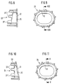
- the embodiment of an element shown in FIGS. 8 and 9 22 differs from the previously described embodiment only because the zigzag base is not on one Plane parallel to the plate 12 but in a plane that is inclined to plate 12, lies.
- the edge formed by the serrations also lies in a plane that is to the plate plane of the ring 12 is inclined.
- the inclination is preferably 8 to 10 °.
- FIGS. 8 and 9 The embodiment of the shown in Figures 10 and 11 Element 24 differs from that in FIGS. 8 and 9 shown embodiment in that the edge portion 20th at an angle to the plate plane, i.e. in a different from 90 ° Angle to the plate plane of the ring 12 is formed.
- Both embodiments that is to say the elements 19, are in operation or 22 as in the previously described embodiments in inserted the jacket so that the ring 12 with its protruding Web 15 in the deepest recesses of the V-shaped Wells 9, 10 rests and the spikes over the edge of the jacket stand out.
- the prongs 21 and 21 'can in 6 and 7 shown embodiment of different lengths be cut off, for example along the dashed line Line 23 so that a wedge-shaped insert is created.
- the edge of the element 22 can also be trimmed in this way that the predetermined angle between the outer edge and the plate-shaped ring 12 is changed. That way it is possible with a few basic elements placeholders with different To form wedge angles.
- the outer contour of the respective rings 12 or 13 becomes natural depending on the respective inner contour of the associated one Coat determined.
- Embodiments can instead of the V-shape, the depressions of the edge also have other shapes, such as U-shaped or slit-shaped depressions.
Abstract
Description
Die Erfindung betrifft einen Platzhalter nach dem Oberbegriff des Patentanspruches 1.The invention relates to a placeholder according to the preamble of claim 1.
Ein solcher Platzhalter ist beispielsweise aus der EP-A-0 268 115 bekannt. Dieser weist auf seiner Innenseite in einem Abstand von dem jeweiligen freien Ende des Mantels einen durch einen Ring gebildeten Anschlag auf. Der Ring ist mittels Schrauben mit dem Mantel verbunden. In einer besonderen Ausführungsform ist auf dem Ring eine Durchbrechungen aufweisende Bodenplatte aufgebracht.Such a placeholder is from, for example EP-A-0 268 115 known. This shows in on its inside a distance from the respective free end of the jacket stop formed by a ring. The ring is by means of Screws connected to the jacket. In a special embodiment is a perforated base plate on the ring upset.
Aufgabe der Erfindung ist es, den Platzhalter einfacher und gleichzeitig universeller auszugestalten.The object of the invention is to make the placeholder easier and to design more universal at the same time.
Diese Aufgabe wird durch den in Patentanspruch 1 gekennzeichneten Platzhalter gelöst.This object is characterized by that in claim 1 Placeholder solved.
Ausführungsformen der Erfindung sind in den Unteransprüchen gekennzeichnet. Embodiments of the invention are characterized in the subclaims.
Weitere Merkmale und Zweckmäßigkeiten der Erfindung ergeben sich aus der Beschreibung von Ausführungsbeispielen anhand der Figuren. Von den Figuren zeigen:
- Fig. 1
- eine Seitenansicht des Mantels des Platzhalters;
- Fig. 2
- eine Draufsicht auf eine erste Ausführungsform des mit dem Mantel zu verbindenden Elementes;
- Fig. 3
- eine Draufsicht auf eine zweite Ausführungsform des Elementes;
- Fig. 3a
- einen Schnitt entlang der Linie IIIA-IIIA in Fig. 3;
- Fig. 4
- eine Draufsicht auf eine dritte Ausführungsform des Elementes;
- Fig. 5
- eine Schnittdarstellung einer Seitenansicht entlang der Linie V-V in Fig. 4;
- Fig. 6
- eine Schnittdarstellung entlang der Linie VI-VI in Fig. 7 durch eine weitere abgewandelte Ausführungsform;
- Fig. 7
- eine Draufsicht auf diese Ausführungsform,
- Fig. 8
- eine Schnittdarstellung entlang der Linie VIII-VIII in Fig. 9;
- Fig. 9
- eine Draufsicht auf diese weitere Ausbildungsform;
- Fig. 10
- eine Schnittdarstellung entlang der Linie X-X in Fig. 11; und
- Fig. 11
- eine Draufsicht auf diese weitere Ausbildungsform.
- Fig. 1
- a side view of the jacket of the placeholder;
- Fig. 2
- a plan view of a first embodiment of the element to be connected to the jacket;
- Fig. 3
- a plan view of a second embodiment of the element;
- Fig. 3a
- a section along the line IIIA-IIIA in Fig. 3;
- Fig. 4
- a plan view of a third embodiment of the element;
- Fig. 5
- a sectional view of a side view along the line VV in Fig. 4;
- Fig. 6
- a sectional view along the line VI-VI in Figure 7 by a further modified embodiment.
- Fig. 7
- a plan view of this embodiment,
- Fig. 8
- a sectional view taken along the line VIII-VIII in Fig. 9;
- Fig. 9
- a top view of this further form of training;
- Fig. 10
- a sectional view taken along line XX in Fig. 11; and
- Fig. 11
- a top view of this further form of training.
Wie insbesondere aus Fig. 1 ersichtlich ist, weist der Platzhalter
einen geschlossenen Mantel 1 auf. Der sich senkrecht zur
Längsachse 2 des Mantels 1 erstreckende Querschnitt ist in
bekannter Weise insbesondere zylindrisch oder oval oder nierenförmig
ausgebildet. Der Mantel 1 weist in der aus Fig. 1
ersichtlichen Weise sich mit ihrer Längsdiagonale parallel zur
Mantelachse 2 erstreckende rautenförmige Ausnehmungen 3, 4 auf.
Jeweils benachbarte Reihen solcher Rauten 3, 4 sind gegeneinander
um eine halbe Rautenhöhe versetzt. Dadurch wird ein Netz von
sich unter einem spitzen Winkel schneidenden Bandstreifen 5, 6
gebildet, die unter jeweils gleich großen Winkeln gegen die
Längsdiagonale der Rauten 3,4 geneigt sind. Der obere Rand 7 und
der untere Rand 8 erstrecken sich jeweils in einer Ebene senkrecht
zu der Längsachse 2. Die Größe der Rauten 3, 4 und der
diese begrenzende Bandstreifen 5, 6 ist so gewählt, daß die
Anzahl von Rauten in Umfangsrichtung stets ganzahlig ist. Durch
das Bilden der Ränder 7, 8 ergibt sich in Umfangsrichtung stets
eine gerade Anzahl von durch den jeweiligen Rautengrund gebildeten
V-förmigen Vertiefungen 9, 10 bzw. 9', 10'. Aufgrund der wie
oben beschrieben gewählten Geometrie weist der jeweilige Rand
quasi eine zu einem Punkt auf der Längsachse 2, der in der Ebene
des Randes liegt, bestehende Punktsymmetrie auf.As can be seen in particular from FIG. 1, the placeholder has
a closed jacket 1. The perpendicular to
Longitudinal axis 2 of the jacket 1 extending cross section is in
known manner in particular cylindrical or oval or kidney-shaped
educated. The jacket 1 has in FIG. 1
evident way with their longitudinal diagonal parallel to
Sheath axis 2 extending diamond-
Das in Fig. 2 gezeigte erste Ausführungsbeispiel eines einen
Anschlag bildenden Elementes 11 ist als ein plattenförmiger Ring
ausgebildet. Der Ring 12 entspricht in seiner Außenkontur der
Innenkontur des Mantels 1. Seine Abmessungen sind so gewählt,
daß er sich in das Innere des Mantels hineindrücken,
gewünschtenfalls aber auch wieder herausdrücken läßt, also durch
Reibsitz mit dem Mantel 1 verbunden ist. An dem Außenrand des
Ringes 12 sind in Umfangsrichtung äquidistant verteilt
hervorspringende Stege 15 vorgesehen. Der Abstand zweier Stege
in Umfangsrichtung ist gleich dem Abstand zweier in
Umfangsrichtung aufeinander folgender V-förmiger Vertiefungen 9,
10. Die Querabmessungen der Stege 15 in der Plattenebene sind so
bemessen, daß die Stege gut in den Grund der V-förmigen
Ausnehmungen 9, 10 hineinpassen. Die Länge der hervorstehenden
Stege entspricht in etwa der Wanddicke des zugehörigen Mantels.The first embodiment shown in Fig. 2 of a
Stop-forming element 11 is a plate-shaped ring
educated. The
Im Fall der Anwendung wird der Mantel 1 durch Abtrennen des oberen
Randes 7 und des unteren Randes 8 auf die gewünschte Länge
gebracht. Dann wird ein Ring 12 auf der Oberseite und ein zweiter
Ring auf der unteren Seite so in das Mantelinnere gedrückt,
daß der jeweilige Ring mit seinen Stegen 15 in den jeweiligen
Grund der zugehörigen V-förmigen Vertiefung 9, 10 bzw. 9', 10'
liegt.In the case of application, the jacket 1 is removed by separating the top
Edge 7 and the
Aufgrund der Tatsache der ganzzahligen Anzahl der V-förmigen Vertiefungen und der sich daraus ergebenden Punktsymmetrie kann ein und dasselbe Element 11 verwendet werden, unabhängig davon, ob die Abtrennung an dem Rand 7 oder an dem gestrichelt angedeuteten darunterliegenden Rand 7' erfolgt. Wird der Rand nicht an der Stelle 7 sondern an der Stelle 7' gebildet, wird der Ring 12 einfach um seine Längsachse gedreht eingesetzt, so daß die Lagerhaltung vereinfacht wird und andererseits auch die Handhabung sehr einfach ist, weil nur eine Art von Ringen zum Einsatz kommt.Due to the fact of the integer number of V-shaped Indentations and the resulting point symmetry can one and the same element 11 are used, regardless of whether the separation on the edge 7 or on the dashed line underlying edge 7 'takes place. The edge is not on the point 7 but formed at the point 7 ', the ring 12th simply inserted rotated around its longitudinal axis, so that warehousing is simplified and on the other hand also the handling is very simple because only one type of ring is used is coming.
Fig. 3 zeigt ein Element 13 einer abgewandelten Ausführungsform.
Auch hier handelt es sich um eine Platte, bei der die Ausnehmungen
durch in der Platte verteilte lochförmige Ausnehmungen 14
gebildet sind. In allen übrigen Merkmalen stimmt das Element mit
dem Element 11 überein.Fig. 3 shows an
Die Figuren 4 und 5 zeigen ein Element 16 einer dritten-Ausführungsform.
Dieses Element weist zunächst wiederum eine Platte
auf, die mit der in Fig. 3 gezeigten Ausführungsform bezüglich
ihrer Ausnehmungen 14 und ihrer Stege 15 identisch ist. Um die
Platte herum ist ein Außenring 17 angeordnet. Dieser erstreckt
sich in der am besten aus Fig. 5 ersichtlichen Weise mit seiner
Ringwandung senkrecht zur Plattenebene und damit parallel zur
äußeren Oberfläche des Mantels 1. Die Lange der Stege 15 ist so
gewählt, daß diese gerade um so viel länger als die Dicke des
Mantels 1 ist, daß der dadurch zwischen Platte, Stegen und Ring
gebildete Zwischenraum 18 ein Aufschieben des Elementes auf das
jeweilige freie Ende 7, 8 des Mantels 1 dahingehend, daß die
Stege 15 in dem Grund der jeweiligen zugehörigen V-förmigen Ausnehmungen
9, 10, 9', 10' liegen, ermöglicht. Der Ring 17 liegt
dann mit seiner inneren Oberfläche an der Außenwand des Mantels
1 an.Figures 4 and 5 show an
In den Figuren 6 und 7 ist ein Element 19 einer weiteren Ausführungsform
beschrieben. Diese weist einen plattenförmigen Ring
12, der mit dem in Fig. 2 gezeigten Ring identisch ist. Auf
einer Oberfläche dieses Ringes ist, wie am besten aus Fig. 6
ersichtlich ist, ein in seiner Außenkontur der Innenkontur des
Mantels 1 entsprechender Randabschnitt 20 vorgesehen, dessen der
Platte 12 abgewandter freier Rand in Umfangsrichtung äquidistant
angeordnete Zacken 21 aufweist. Die Höhe der Zacken 21 über der
Platte 12 ist so bemessen, daß die Zacken im eingesetzten
Zustand nahezu bis zu ihrem Grund über den Rand 7 bzw. 8 des
Mantels 1 hervorstehen.In Figures 6 and 7 is an
Die in den Figuren 8 und 9 gezeigte Ausführungsform eines Elementes
22 unterscheidet sich von der vorher beschriebenen Ausführungsform
nur dadurch, daß der Zackengrund nicht auf einer
Ebene parallel zur Platte 12 sondern in einer Ebene, die geneigt
zur Platte 12 ist, liegt. Der von den Zacken gebildete Rand
liegt ebenfalls in einer Ebene, die zu der Plattenebene des Ringes
12 geneigt ist. Die Neigung beträgt vorzugsweise 8 bis 10°.The embodiment of an element shown in FIGS. 8 and 9
22 differs from the previously described embodiment
only because the zigzag base is not on one
Plane parallel to the
Die in den Figuren 10 und 11 gezeigte Ausführungsform des
Elementes 24 unterscheidet sich von der in den Figuren 8 und 9
gezeigten Ausführungsform dadurch, daß der Randabschnitt 20
schräg zu der Plattenebene, d.h. in einem von 90° verschiedenen
Winkel zur Plattenebene des Ringes 12, ausgebildet ist.The embodiment of the shown in Figures 10 and 11
Im Betrieb werden beide Ausführungsformen, also die Elemente 19
bzw. 22 wie bei den vorher beschriebenen Ausführungsformen in
den Mantel eingesetzt, so daß der Ring 12 mit seinen hervorstehenden
Stegen 15 in den tiefsten Ausnehmungen der V-förmigen
Vertiefungen 9, 10 ruht und die Zacken über den Mantelrand nach
außen hervorstehen. Die Zacken 21 bzw. 21' können bei der in
Fig. 6 und 7 gezeigten Ausführungsform unterschiedlich lang
abgeschnitten werden, beispielsweise entlang der gestrichelten
Linie 23, so daß ein keilförmiger Einsatz entsteht. In gleicher
Weise kann auch der Rand des Elementes 22 so beschnitten werden,
daß der vorgegebene Winkel zwischen dem äußeren Rand und dem
plattenförmigen Ring 12 verändert wird. Auf diese Weise ist es
möglich, mit wenigen Grundelementen Platzhalter mit verschiedenen
Keilwinkeln zu bilden.Both embodiments, that is to say the
Die Außenkontur der jeweiligen Ringe 12 bzw. 13 wird natürlich
in Abhängigkeit von der jeweiligen Innenkontur des zugehörigen
Mantels bestimmt.The outer contour of the
In Abweichung von den oben beschriebenen besonders bevorzugten Ausführungsbeispielen können anstelle der V-Form die Vertiefungen des Randes auch andere Formen haben, etwa U-förmige oder schlitzförmige Vertiefungen.In deviation from the particularly preferred ones described above Embodiments can instead of the V-shape, the depressions of the edge also have other shapes, such as U-shaped or slit-shaped depressions.
Claims (15)
- A spacer device, in particular for a vertebra or a vertebral disc, having a sheathing (1) which has recesses, a first and second edge (7, 8) and mutually adjacent depressions (9, 10; 9', 10') arranged in the peripheral direction and extending in each case in the direction of the other edge, and a stop provided at at least one of the ends at a spacing from the outer edge, the stop being formed by an element (11, 13, 16, 19, 22) whereof the outer contour corresponds to the inner contour of the sheathing (1), characterized in that, at the periphery of the element (11, 13, 16, 19, 22), web-type projections (15) for engaging in the depressions are provided at the points corresponding to the depressions (9, 10; 9', 10') in the sheathing (1).
- A spacer device according to Claim 1, characterized in that the depressions are constructed as V-shaped recesses (9, 10; 9', 10') in each case having an equal spacing from one another.
- A spacer device according to Claim 1 or 2, characterized in that the outer contour is dimensioned such that the element (11, 13, 16, 19, 22) is held with frictional fit by the sheathing (1).
- A spacer device according to one of Claims 1 to 3, characterized in that the sheathing (1) is formed from a lattice having rhomboidal recesses (3, 4).
- A spacer device according to Claim 4, characterized in that a diagonal of the rhombi (3, 4) extends in each case parallel to the longitudinal axis (2) of the spacer device.
- A spacer device according to one of Claims 1 to 5, characterized in that the element (11, 13, 16) is constructed as a plate.
- A spacer device according to Claim 6, characterized in that the plate (12) is of an annular construction.
- A spacer device according to Claim 6, characterized in that the plate (13) has a plurality of mutually adjacent holes (14).
- A spacer device according to one of Claims 6 to 8, characterized in that the length of the webs (15) is at least equal to the wall thickness of the sheathing (1).
- A spacer device according to Claim 9, characterized in that an outer ring (17) extending about the element (13) is provided at the outer ends of the webs (15), the contour of which outer ring corresponds to the outer contour of the sheathing (1) and the annular wall of which outer ring extends perpendicularly to the plane of the plate (13) and parallel to the outer surface of the sheathing (1).
- A spacer device according to Claim 10, characterized in that the outer ring (17) is connected along its centre line to the webs (15).
- A spacer device according to Claims 1 to 11, characterized in that an indented edge (21, 21') projecting beyond the free edge of the sheathing (1) is provided on the side of the element (19, 22) which faces the adjoining end.
- A spacer device according to Claim 12, characterized in that the indented edge extends parallel to the plate (12).
- A spacer device according to Claim 12, characterized in that the indented edge extends obliquely with respect to the plate (12).
- A spacer device according to one of Claims 1 to 14, characterized in that the edge has an even number of equidistant depressions.
Applications Claiming Priority (2)
| Application Number | Priority Date | Filing Date | Title |
|---|---|---|---|
| DE19504867A DE19504867C1 (en) | 1995-02-14 | 1995-02-14 | Position retainer for spine |
| DE19504867 | 1995-02-14 |
Publications (2)
| Publication Number | Publication Date |
|---|---|
| EP0727196A1 EP0727196A1 (en) | 1996-08-21 |
| EP0727196B1 true EP0727196B1 (en) | 1998-10-07 |
Family
ID=7753908
Family Applications (1)
| Application Number | Title | Priority Date | Filing Date |
|---|---|---|---|
| EP95120302A Expired - Lifetime EP0727196B1 (en) | 1995-02-14 | 1995-12-21 | Device for reserving space, especially for a vertebra or for a spinal disc |
Country Status (8)
| Country | Link |
|---|---|
| US (3) | US5702451A (en) |
| EP (1) | EP0727196B1 (en) |
| JP (1) | JP3089201B2 (en) |
| KR (1) | KR100395192B1 (en) |
| AT (1) | ATE171857T1 (en) |
| CA (1) | CA2169233A1 (en) |
| DE (2) | DE19504867C1 (en) |
| ES (1) | ES2124489T3 (en) |
Families Citing this family (235)
| Publication number | Priority date | Publication date | Assignee | Title |
|---|---|---|---|---|
| JPH0524997U (en) * | 1991-09-09 | 1993-04-02 | セイレイ工業株式会社 | Cooling fan speed controller |
| EP1504732B1 (en) | 1995-03-27 | 2007-05-23 | Warsaw Orthopedic, Inc. | Spinal fusion implant |
| DE29616778U1 (en) * | 1996-09-26 | 1998-01-29 | Howmedica Gmbh | Vertebral body placeholder |
| US6416515B1 (en) | 1996-10-24 | 2002-07-09 | Spinal Concepts, Inc. | Spinal fixation system |
| JP2002514100A (en) | 1996-10-24 | 2002-05-14 | スピナル コンセプツ,インク. | Method and apparatus for fixing a spine |
| US6045579A (en) | 1997-05-01 | 2000-04-04 | Spinal Concepts, Inc. | Adjustable height fusion device |
| US6585770B1 (en) | 1997-06-02 | 2003-07-01 | Sdgi Holdings, Inc. | Devices for supporting bony structures |
| US5928243A (en) | 1997-07-16 | 1999-07-27 | Spinal Concepts, Inc. | Pedicle probe and depth gage |
| US6030389A (en) | 1997-08-04 | 2000-02-29 | Spinal Concepts, Inc. | System and method for stabilizing the human spine with a bone plate |
| US6454769B2 (en) | 1997-08-04 | 2002-09-24 | Spinal Concepts, Inc. | System and method for stabilizing the human spine with a bone plate |
| US6053921A (en) | 1997-08-26 | 2000-04-25 | Spinal Concepts, Inc. | Surgical cable system and method |
| US5964769A (en) | 1997-08-26 | 1999-10-12 | Spinal Concepts, Inc. | Surgical cable system and method |
| DE59710623D1 (en) | 1997-09-30 | 2003-09-25 | Ct Pulse Orthopedics Ltd | Tubular support body for bridging two vertebrae |
| DE29720022U1 (en) * | 1997-11-12 | 1998-01-15 | Schaefer Micomed Gmbh | Intervertebral implant |
| US6086613A (en) | 1997-12-23 | 2000-07-11 | Depuy Acromed, Inc. | Spacer assembly for use in spinal surgeries |
| DE19818143A1 (en) * | 1998-04-23 | 1999-10-28 | Medinorm Ag | Device for connecting vertebrae of the spine |
| WO1999060956A1 (en) | 1998-05-27 | 1999-12-02 | Nuvasive, Inc. | Interlocking spinal inserts |
| US6290724B1 (en) | 1998-05-27 | 2001-09-18 | Nuvasive, Inc. | Methods for separating and stabilizing adjacent vertebrae |
| US6368325B1 (en) | 1998-05-27 | 2002-04-09 | Nuvasive, Inc. | Bone blocks and methods for inserting bone blocks into intervertebral spaces |
| GB2338652A (en) * | 1998-06-23 | 1999-12-29 | Biomet Merck Ltd | Vertebral body replacement |
| TW519488B (en) * | 1999-02-04 | 2003-02-01 | Synthes Ag | End member for a bone fusion implant |
| US6929662B1 (en) | 1999-02-04 | 2005-08-16 | Synthes (Usa) | End member for a bone fusion implant |
| CA2363254C (en) | 1999-03-07 | 2009-05-05 | Discure Ltd. | Method and apparatus for computerized surgery |
| US6557226B1 (en) | 1999-04-23 | 2003-05-06 | Michael E. Landry | Apparatus for manufacturing a bone dowel |
| US20060247665A1 (en) | 1999-05-28 | 2006-11-02 | Ferree Bret A | Methods and apparatus for treating disc herniation and preventing the extrusion of interbody bone graft |
| US7273497B2 (en) | 1999-05-28 | 2007-09-25 | Anova Corp. | Methods for treating a defect in the annulus fibrosis |
| US20070038231A1 (en) | 1999-05-28 | 2007-02-15 | Ferree Bret A | Methods and apparatus for treating disc herniation and preventing the extrusion of interbody bone graft |
| US6520996B1 (en) | 1999-06-04 | 2003-02-18 | Depuy Acromed, Incorporated | Orthopedic implant |
| FR2897259B1 (en) | 2006-02-15 | 2008-05-09 | Ldr Medical Soc Par Actions Si | INTERSOMATIC TRANSFORAMINAL CAGE WITH INTERBREBAL FUSION GRAFT AND CAGE IMPLANTATION INSTRUMENT |
| US7553329B2 (en) | 1999-08-18 | 2009-06-30 | Intrinsic Therapeutics, Inc. | Stabilized intervertebral disc barrier |
| US8323341B2 (en) | 2007-09-07 | 2012-12-04 | Intrinsic Therapeutics, Inc. | Impaction grafting for vertebral fusion |
| EP1624832A4 (en) | 1999-08-18 | 2008-12-24 | Intrinsic Therapeutics Inc | Devices and method for augmenting a vertebral disc nucleus |
| US6425919B1 (en) | 1999-08-18 | 2002-07-30 | Intrinsic Orthopedics, Inc. | Devices and methods of vertebral disc augmentation |
| US7998213B2 (en) | 1999-08-18 | 2011-08-16 | Intrinsic Therapeutics, Inc. | Intervertebral disc herniation repair |
| US7717961B2 (en) | 1999-08-18 | 2010-05-18 | Intrinsic Therapeutics, Inc. | Apparatus delivery in an intervertebral disc |
| US7094258B2 (en) | 1999-08-18 | 2006-08-22 | Intrinsic Therapeutics, Inc. | Methods of reinforcing an annulus fibrosis |
| US7972337B2 (en) | 2005-12-28 | 2011-07-05 | Intrinsic Therapeutics, Inc. | Devices and methods for bone anchoring |
| IL155494A0 (en) | 1999-08-18 | 2003-11-23 | Intrinsic Therapeutics Inc | Devices and method for nucleus pulposus augmentation and retention |
| US6783546B2 (en) | 1999-09-13 | 2004-08-31 | Keraplast Technologies, Ltd. | Implantable prosthetic or tissue expanding device |
| US8128698B2 (en) | 1999-10-20 | 2012-03-06 | Anulex Technologies, Inc. | Method and apparatus for the treatment of the intervertebral disc annulus |
| US8632590B2 (en) | 1999-10-20 | 2014-01-21 | Anulex Technologies, Inc. | Apparatus and methods for the treatment of the intervertebral disc |
| US6592625B2 (en) | 1999-10-20 | 2003-07-15 | Anulex Technologies, Inc. | Spinal disc annulus reconstruction method and spinal disc annulus stent |
| US7935147B2 (en) | 1999-10-20 | 2011-05-03 | Anulex Technologies, Inc. | Method and apparatus for enhanced delivery of treatment device to the intervertebral disc annulus |
| US7052516B2 (en) | 1999-10-20 | 2006-05-30 | Anulex Technologies, Inc. | Spinal disc annulus reconstruction method and deformable spinal disc annulus stent |
| US7951201B2 (en) | 1999-10-20 | 2011-05-31 | Anulex Technologies, Inc. | Method and apparatus for the treatment of the intervertebral disc annulus |
| CA2387042A1 (en) * | 1999-10-20 | 2001-04-26 | Sdgi Holdings, Inc. | Impacted orthopedic bone support implant |
| US7615076B2 (en) | 1999-10-20 | 2009-11-10 | Anulex Technologies, Inc. | Method and apparatus for the treatment of the intervertebral disc annulus |
| US7004970B2 (en) | 1999-10-20 | 2006-02-28 | Anulex Technologies, Inc. | Methods and devices for spinal disc annulus reconstruction and repair |
| US6764491B2 (en) | 1999-10-21 | 2004-07-20 | Sdgi Holdings, Inc. | Devices and techniques for a posterior lateral disc space approach |
| WO2001028469A2 (en) | 1999-10-21 | 2001-04-26 | Sdgi Holdings, Inc. | Devices and techniques for a posterior lateral disc space approach |
| US6830570B1 (en) * | 1999-10-21 | 2004-12-14 | Sdgi Holdings, Inc. | Devices and techniques for a posterior lateral disc space approach |
| DE19957339C2 (en) * | 1999-11-29 | 2002-03-28 | Franz Copf | Cage element, as well as set of cage elements |
| US6331179B1 (en) | 2000-01-06 | 2001-12-18 | Spinal Concepts, Inc. | System and method for stabilizing the human spine with a bone plate |
| US6447512B1 (en) | 2000-01-06 | 2002-09-10 | Spinal Concepts, Inc. | Instrument and method for implanting an interbody fusion device |
| US6296665B1 (en) * | 2000-03-20 | 2001-10-02 | Electro-Biology, Inc. | Method and apparatus for spinal fixation |
| WO2001070139A2 (en) * | 2000-03-22 | 2001-09-27 | Synthes (U.S.A) | Skeletal reconstruction cages |
| AR027685A1 (en) * | 2000-03-22 | 2003-04-09 | Synthes Ag | METHOD AND METHOD FOR CARRYING OUT |
| US6805695B2 (en) | 2000-04-04 | 2004-10-19 | Spinalabs, Llc | Devices and methods for annular repair of intervertebral discs |
| WO2001093786A2 (en) | 2000-06-05 | 2001-12-13 | Tensegra, Inc. | Orthopedic implant and method of making metal articles |
| US6579318B2 (en) | 2000-06-12 | 2003-06-17 | Ortho Development Corporation | Intervertebral spacer |
| USD501555S1 (en) | 2000-06-12 | 2005-02-01 | Ortho Development Corporation | Implant |
| US6852126B2 (en) | 2000-07-17 | 2005-02-08 | Nuvasive, Inc. | Stackable interlocking intervertebral support system |
| DE10055891A1 (en) * | 2000-11-10 | 2002-06-06 | Biedermann Motech Gmbh | bone screw |
| US6890343B2 (en) | 2000-12-14 | 2005-05-10 | Ensure Medical, Inc. | Plug with detachable guidewire element and methods for use |
| US8083768B2 (en) | 2000-12-14 | 2011-12-27 | Ensure Medical, Inc. | Vascular plug having composite construction |
| US6623509B2 (en) | 2000-12-14 | 2003-09-23 | Core Medical, Inc. | Apparatus and methods for sealing vascular punctures |
| US6896692B2 (en) | 2000-12-14 | 2005-05-24 | Ensure Medical, Inc. | Plug with collet and apparatus and method for delivering such plugs |
| US6846319B2 (en) | 2000-12-14 | 2005-01-25 | Core Medical, Inc. | Devices for sealing openings through tissue and apparatus and methods for delivering them |
| WO2002056802A1 (en) * | 2000-12-15 | 2002-07-25 | Spineology, Inc. | Annulus-reinforcing band |
| US20030078660A1 (en) * | 2001-02-15 | 2003-04-24 | Dale Clifford | Orthopedic implant and method for orthopedic treatment |
| WO2002071986A2 (en) * | 2001-03-13 | 2002-09-19 | Depuy International Ltd. | Vertebral body replacement device |
| US20040083002A1 (en) * | 2001-04-06 | 2004-04-29 | Belef William Martin | Methods for treating spinal discs |
| US6719795B1 (en) * | 2001-04-25 | 2004-04-13 | Macropore Biosurgery, Inc. | Resorbable posterior spinal fusion system |
| US6736815B2 (en) | 2001-09-06 | 2004-05-18 | Core Medical, Inc. | Apparatus and methods for treating spinal discs |
| US6923814B1 (en) | 2001-10-30 | 2005-08-02 | Nuvasive, Inc. | System and methods for cervical spinal fusion |
| US7766947B2 (en) | 2001-10-31 | 2010-08-03 | Ortho Development Corporation | Cervical plate for stabilizing the human spine |
| US7527649B1 (en) | 2002-02-15 | 2009-05-05 | Nuvasive, Inc. | Intervertebral implant and related methods |
| AR038680A1 (en) | 2002-02-19 | 2005-01-26 | Synthes Ag | INTERVERTEBRAL IMPLANT |
| US6808538B2 (en) * | 2002-03-15 | 2004-10-26 | Stryker Spine | Vertebral body spacer having variable wedged endplates |
| US7309358B2 (en) | 2002-03-21 | 2007-12-18 | Warsaw Orthopedic, Inc. | Vertebral body and disc space replacement devices |
| US6991653B2 (en) * | 2002-03-21 | 2006-01-31 | Sdgi Holdings, Inc. | Vertebral body and disc space replacement devices |
| US6758862B2 (en) * | 2002-03-21 | 2004-07-06 | Sdgi Holdings, Inc. | Vertebral body and disc space replacement devices |
| US6783547B2 (en) | 2002-04-05 | 2004-08-31 | Howmedica Corp. | Apparatus for fusing adjacent bone structures |
| US7618423B1 (en) | 2002-06-15 | 2009-11-17 | Nuvasive, Inc. | System and method for performing spinal fusion |
| DE10238306B4 (en) * | 2002-08-21 | 2005-03-24 | Biedermann Motech Gmbh | Method for producing a tubular spacer and placeholder |
| DE10242331B4 (en) * | 2002-09-12 | 2005-10-20 | Biedermann Motech Gmbh | Placeholder for vertebral bodies or intervertebral discs |
| DE10242329B4 (en) * | 2002-09-12 | 2005-03-17 | Biedermann Motech Gmbh | Disc prosthesis |
| US7776049B1 (en) | 2002-10-02 | 2010-08-17 | Nuvasive, Inc. | Spinal implant inserter, implant, and method |
| US7232463B2 (en) * | 2002-10-23 | 2007-06-19 | U.S. Spinal Technologies, Llc | Intervertebral cage designs |
| CA2515247C (en) | 2003-02-06 | 2010-10-05 | Synthes (U.S.A.) | Intervertebral implant |
| DE10311477A1 (en) * | 2003-03-15 | 2004-09-23 | Ulrich Gmbh & Co. Kg | Implant to be inserted between the vertebral body of the spine |
| US20040186569A1 (en) * | 2003-03-20 | 2004-09-23 | Berry Bret M. | Height adjustable vertebral body and disc space replacement devices |
| WO2004084742A1 (en) | 2003-03-24 | 2004-10-07 | Theken Surgical Llc | Spinal implant adjustment device |
| US7819903B2 (en) | 2003-03-31 | 2010-10-26 | Depuy Spine, Inc. | Spinal fixation plate |
| US7377930B2 (en) * | 2003-04-02 | 2008-05-27 | Frank Loughran | Nerve protecting tube |
| AU2003213972B2 (en) * | 2003-04-11 | 2007-06-28 | Synthes Gmbh | Anchoring means for intervertebral implants |
| AU2004249291B2 (en) | 2003-06-20 | 2009-07-23 | Intrinsic Therapeutics, Inc. | Device and method for delivering an implant through an annular defect in an intervertebral disc |
| US7141068B2 (en) * | 2003-07-01 | 2006-11-28 | Thomas Ross | Spinal spacer assembly |
| US8062365B2 (en) * | 2003-08-04 | 2011-11-22 | Warsaw Orthopedic, Inc. | Bone supporting devices with bio-absorbable end members |
| DE10337088A1 (en) * | 2003-08-12 | 2005-03-10 | Biedermann Motech Gmbh | Placeholder for vertebral bodies or intervertebral discs |
| US7226482B2 (en) | 2003-09-02 | 2007-06-05 | Synthes (U.S.A.) | Multipiece allograft implant |
| DE10348329B3 (en) | 2003-10-17 | 2005-02-17 | Biedermann Motech Gmbh | Rod-shaped element used in spinal column and accident surgery for connecting two bone-anchoring elements comprises a rigid section and an elastic section that are made in one piece |
| DE102004021861A1 (en) * | 2004-05-04 | 2005-11-24 | Biedermann Motech Gmbh | Implant for temporary or permanent replacement of vertebra or intervertebral disk, comprising solid central element and outer elements with openings |
| US7361183B2 (en) | 2003-10-17 | 2008-04-22 | Ensure Medical, Inc. | Locator and delivery device and method of use |
| US8852229B2 (en) | 2003-10-17 | 2014-10-07 | Cordis Corporation | Locator and closure device and method of use |
| ATE380530T1 (en) * | 2003-10-17 | 2007-12-15 | Co Ligne Ag | FUSION IMPLANT |
| JP2007508085A (en) * | 2003-10-17 | 2007-04-05 | ヴィーダーマン モテッヒ ゲーエムベーハー | Flexible implant |
| US8632570B2 (en) | 2003-11-07 | 2014-01-21 | Biedermann Technologies Gmbh & Co. Kg | Stabilization device for bones comprising a spring element and manufacturing method for said spring element |
| US7238205B2 (en) * | 2004-01-15 | 2007-07-03 | Warsaw Orthopedic, Inc. | Universal interference cleat |
| GB0401362D0 (en) * | 2004-01-22 | 2004-02-25 | Depuy Int Ltd | Vertebral fusion parts, devices and methods |
| US7918891B1 (en) * | 2004-03-29 | 2011-04-05 | Nuvasive Inc. | Systems and methods for spinal fusion |
| KR101276414B1 (en) * | 2004-05-04 | 2013-06-19 | 비이더만 테크놀로지스 게엠베하 & 코. 카게 | Flexible space holder |
| ATE524121T1 (en) | 2004-11-24 | 2011-09-15 | Abdou Samy | DEVICES FOR PLACING AN ORTHOPEDIC INTERVERTEBRAL IMPLANT |
| US20060229613A1 (en) * | 2004-12-31 | 2006-10-12 | Timm Jens P | Sheath assembly for spinal stabilization device |
| US8926654B2 (en) | 2005-05-04 | 2015-01-06 | Cordis Corporation | Locator and closure device and method of use |
| US8088144B2 (en) | 2005-05-04 | 2012-01-03 | Ensure Medical, Inc. | Locator and closure device and method of use |
| US8758442B2 (en) | 2005-05-06 | 2014-06-24 | Titan Spine, Llc | Composite implants having integration surfaces composed of a regular repeating pattern |
| US11096796B2 (en) | 2005-05-06 | 2021-08-24 | Titan Spine, Llc | Interbody spinal implant having a roughened surface topography on one or more internal surfaces |
| US9168147B2 (en) | 2005-05-06 | 2015-10-27 | Titan Spine, Llc | Self-deploying locking screw retention device |
| US8591590B2 (en) * | 2005-05-06 | 2013-11-26 | Titan Spine, Llc | Spinal implant having a transverse aperture |
| US20120312779A1 (en) | 2005-05-06 | 2012-12-13 | Titian Spine, LLC | Methods for manufacturing implants having integration surfaces |
| US8551176B2 (en) | 2005-05-06 | 2013-10-08 | Titan Spine, Llc | Spinal implant having a passage for enhancing contact between bone graft material and cortical endplate bone |
| US8617248B2 (en) | 2005-05-06 | 2013-12-31 | Titan Spine, Llc | Spinal implant having variable ratios of the integration surface area to the axial passage area |
| US8585765B2 (en) | 2005-05-06 | 2013-11-19 | Titan Spine, Llc | Endplate-preserving spinal implant having a raised expulsion-resistant edge |
| US8585766B2 (en) * | 2005-05-06 | 2013-11-19 | Titan Spine, Llc | Endplate-preserving spinal implant with an integration plate having durable connectors |
| US8545568B2 (en) | 2005-05-06 | 2013-10-01 | Titan Spine, Llc | Method of using instruments and interbody spinal implants to enhance distraction |
| US8585767B2 (en) * | 2005-05-06 | 2013-11-19 | Titan Spine, Llc | Endplate-preserving spinal implant with an integration plate having durable connectors |
| US8814939B2 (en) | 2005-05-06 | 2014-08-26 | Titan Spine, Llc | Implants having three distinct surfaces |
| US8562684B2 (en) * | 2005-05-06 | 2013-10-22 | Titan Spine, Llc | Endplate-preserving spinal implant with an integration plate having a roughened surface topography |
| US9125756B2 (en) | 2005-05-06 | 2015-09-08 | Titan Spine, Llc | Processes for producing regular repeating patterns on surfaces of interbody devices |
| US8435302B2 (en) | 2005-05-06 | 2013-05-07 | Titan Spine, Llc | Instruments and interbody spinal implants enhancing disc space distraction |
| US8758443B2 (en) | 2005-05-06 | 2014-06-24 | Titan Spine, Llc | Implants with integration surfaces having regular repeating surface patterns |
| US8562685B2 (en) | 2005-05-06 | 2013-10-22 | Titan Spine, Llc | Spinal implant and integration plate for optimizing vertebral endplate contact load-bearing edges |
| US8262737B2 (en) | 2005-05-06 | 2012-09-11 | Titan Spine, Llc | Composite interbody spinal implant having openings of predetermined size and shape |
| US8992622B2 (en) | 2005-05-06 | 2015-03-31 | Titan Spine, Llc | Interbody spinal implant having a roughened surface topography |
| WO2006130796A2 (en) * | 2005-06-02 | 2006-12-07 | Zimmer Spine, Inc. | Interbody fusion ring and method of using the same |
| US8623088B1 (en) | 2005-07-15 | 2014-01-07 | Nuvasive, Inc. | Spinal fusion implant and related methods |
| US8328851B2 (en) | 2005-07-28 | 2012-12-11 | Nuvasive, Inc. | Total disc replacement system and related methods |
| DE602005007223D1 (en) | 2005-08-24 | 2008-07-10 | Biedermann Motech Gmbh | Rod-shaped element for use in spine or trauma surgery and stabilization device with such an element |
| US7674294B2 (en) * | 2005-12-01 | 2010-03-09 | Warsaw Orthopedic, Inc. | End device for a vertebral implant |
| DE102005061932A1 (en) * | 2005-12-23 | 2007-07-05 | Biedermann Motech Gmbh | Placeholder for implantation to the human vertebrae has three tubular bodies having different lengths and diameters that are inserted and connected to each other by pins so that they project over the edges of the next larger tubular body |
| US8062372B2 (en) * | 2005-12-29 | 2011-11-22 | Industrial Technology Research Institute | Spinal fusion device |
| US7935148B2 (en) | 2006-01-09 | 2011-05-03 | Warsaw Orthopedic, Inc. | Adjustable insertion device for a vertebral implant |
| US20070161962A1 (en) * | 2006-01-09 | 2007-07-12 | Edie Jason A | Device and method for moving fill material to an implant |
| WO2007098288A2 (en) | 2006-02-27 | 2007-08-30 | Synthes (U.S.A.) | Intervertebral implant with fixation geometry |
| US8657882B2 (en) * | 2006-04-24 | 2014-02-25 | Warsaw Orthopedic, Inc. | Expandable intervertebral devices and methods of use |
| US20070270960A1 (en) * | 2006-04-24 | 2007-11-22 | Sdgi Holdings, Inc. | Extendable anchor in a vertebral implant and methods of use |
| US8187331B2 (en) * | 2006-04-27 | 2012-05-29 | Warsaw Orthopedic, Inc. | Expandable vertebral implant and methods of use |
| US7794501B2 (en) * | 2006-04-27 | 2010-09-14 | Wasaw Orthopedic, Inc. | Expandable intervertebral spacers and methods of use |
| US7708779B2 (en) | 2006-05-01 | 2010-05-04 | Warsaw Orthopedic, Inc. | Expandable intervertebral spacers and methods of use |
| WO2010062971A1 (en) | 2008-11-26 | 2010-06-03 | Anova Corporation | Methods and apparatus for anulus repair |
| US8764835B2 (en) | 2006-06-13 | 2014-07-01 | Bret A. Ferree | Intervertebral disc treatment methods and apparatus |
| US8834496B2 (en) | 2006-06-13 | 2014-09-16 | Bret A. Ferree | Soft tissue repair methods and apparatus |
| US9232938B2 (en) | 2006-06-13 | 2016-01-12 | Anova Corp. | Method and apparatus for closing fissures in the annulus fibrosus |
| ES2390567T3 (en) | 2006-07-14 | 2012-11-14 | Biedermann Technologies Gmbh & Co. Kg | Separator for insertion between two vertebrae |
| USD741488S1 (en) | 2006-07-17 | 2015-10-20 | Nuvasive, Inc. | Spinal fusion implant |
| US7862618B2 (en) * | 2006-07-19 | 2011-01-04 | Warsaw Orthopedic, Inc. | Expandable vertebral body implants and methods of use |
| US20080077248A1 (en) * | 2006-09-22 | 2008-03-27 | Alphatec Spine, Inc. | Vertebral body replacement |
| US7815683B2 (en) * | 2006-10-16 | 2010-10-19 | Warsaw Orthopedic, Inc. | Implants with helical supports and methods of use for spacing vertebral members |
| US8328871B2 (en) | 2006-11-09 | 2012-12-11 | Warsaw Orthopedic, Inc. | Expanding vertebral body implant |
| US8062366B2 (en) | 2007-01-08 | 2011-11-22 | Warsaw Orthopedic, Inc. | Ratcheting expandable corpectomy/vertebrectomy cage |
| US8673005B1 (en) | 2007-03-07 | 2014-03-18 | Nuvasive, Inc. | System and methods for spinal fusion |
| US8480715B2 (en) | 2007-05-22 | 2013-07-09 | Zimmer Spine, Inc. | Spinal implant system and method |
| US20110196492A1 (en) | 2007-09-07 | 2011-08-11 | Intrinsic Therapeutics, Inc. | Bone anchoring systems |
| USD671645S1 (en) | 2007-09-18 | 2012-11-27 | Nuvasive, Inc. | Intervertebral implant |
| US8591587B2 (en) * | 2007-10-30 | 2013-11-26 | Aesculap Implant Systems, Llc | Vertebral body replacement device and method for use to maintain a space between two vertebral bodies within a spine |
| BRPI0820172A2 (en) | 2007-11-16 | 2015-06-16 | Synthes Gmbh | Low Profile Intervertebral Implant |
| US8241294B2 (en) | 2007-12-19 | 2012-08-14 | Depuy Spine, Inc. | Instruments for expandable corpectomy spinal fusion cage |
| US8241363B2 (en) | 2007-12-19 | 2012-08-14 | Depuy Spine, Inc. | Expandable corpectomy spinal fusion cage |
| US9101491B2 (en) | 2007-12-28 | 2015-08-11 | Nuvasive, Inc. | Spinal surgical implant and related methods |
| US8425608B2 (en) * | 2008-01-18 | 2013-04-23 | Warsaw Orthopedic, Inc. | Lordotic expanding vertebral body spacer |
| US8083796B1 (en) | 2008-02-29 | 2011-12-27 | Nuvasive, Inc. | Implants and methods for spinal fusion |
| US8163022B2 (en) | 2008-10-14 | 2012-04-24 | Anulex Technologies, Inc. | Method and apparatus for the treatment of the intervertebral disc annulus |
| USD621509S1 (en) | 2008-10-15 | 2010-08-10 | Nuvasive, Inc. | Intervertebral implant |
| BRPI0921486A2 (en) | 2008-11-07 | 2019-09-10 | Synthes Gmbh | vertebral intercorporeal unit of spacer and coupled plate |
| CA2746505C (en) * | 2008-12-18 | 2017-06-13 | 4-Web Spine, Inc. | Truss implant |
| USD754346S1 (en) | 2009-03-02 | 2016-04-19 | Nuvasive, Inc. | Spinal fusion implant |
| US9687357B2 (en) | 2009-03-12 | 2017-06-27 | Nuvasive, Inc. | Vertebral body replacement |
| US9387090B2 (en) | 2009-03-12 | 2016-07-12 | Nuvasive, Inc. | Vertebral body replacement |
| US8287597B1 (en) | 2009-04-16 | 2012-10-16 | Nuvasive, Inc. | Method and apparatus for performing spine surgery |
| US9351845B1 (en) | 2009-04-16 | 2016-05-31 | Nuvasive, Inc. | Method and apparatus for performing spine surgery |
| US8876905B2 (en) | 2009-04-29 | 2014-11-04 | DePuy Synthes Products, LLC | Minimally invasive corpectomy cage and instrument |
| USD731063S1 (en) | 2009-10-13 | 2015-06-02 | Nuvasive, Inc. | Spinal fusion implant |
| US8764806B2 (en) | 2009-12-07 | 2014-07-01 | Samy Abdou | Devices and methods for minimally invasive spinal stabilization and instrumentation |
| US8652153B2 (en) | 2010-01-11 | 2014-02-18 | Anulex Technologies, Inc. | Intervertebral disc annulus repair system and bone anchor delivery tool |
| US8425611B2 (en) | 2010-10-26 | 2013-04-23 | Warsaw Orthopedic, Inc. | Expandable orthopedic implant system and method |
| US20120109303A1 (en) * | 2010-10-28 | 2012-05-03 | Warsaw Orthopedic, Inc. | Implant assemblies, devices and methods for providing stabilization between first and second vertebrae |
| WO2012088238A2 (en) | 2010-12-21 | 2012-06-28 | Synthes Usa, Llc | Intervertebral implants, systems, and methods of use |
| US9241809B2 (en) | 2010-12-21 | 2016-01-26 | DePuy Synthes Products, Inc. | Intervertebral implants, systems, and methods of use |
| US8377140B2 (en) | 2011-01-12 | 2013-02-19 | Ebi, Llc | Expandable spinal implant device |
| US8845728B1 (en) | 2011-09-23 | 2014-09-30 | Samy Abdou | Spinal fixation devices and methods of use |
| US9198765B1 (en) | 2011-10-31 | 2015-12-01 | Nuvasive, Inc. | Expandable spinal fusion implants and related methods |
| US8992619B2 (en) | 2011-11-01 | 2015-03-31 | Titan Spine, Llc | Microstructured implant surfaces |
| USD675320S1 (en) | 2011-11-03 | 2013-01-29 | Nuvasive, Inc. | Intervertebral implant |
| USD721808S1 (en) | 2011-11-03 | 2015-01-27 | Nuvasive, Inc. | Intervertebral implant |
| US20130226240A1 (en) | 2012-02-22 | 2013-08-29 | Samy Abdou | Spinous process fixation devices and methods of use |
| AU2013235264B2 (en) | 2012-03-20 | 2017-09-28 | Titan Spine, Inc. | Friction-fit spinal endplate and endplate-preserving method |
| US9198767B2 (en) | 2012-08-28 | 2015-12-01 | Samy Abdou | Devices and methods for spinal stabilization and instrumentation |
| CN104780870B (en) | 2012-09-25 | 2018-03-02 | 4网络公司 | Programmable implant and the method for repairing bone structure using programmable implant |
| EP2716261A1 (en) | 2012-10-02 | 2014-04-09 | Titan Spine, LLC | Implants with self-deploying anchors |
| US9498349B2 (en) | 2012-10-09 | 2016-11-22 | Titan Spine, Llc | Expandable spinal implant with expansion wedge and anchor |
| US9320617B2 (en) | 2012-10-22 | 2016-04-26 | Cogent Spine, LLC | Devices and methods for spinal stabilization and instrumentation |
| US9737294B2 (en) | 2013-01-28 | 2017-08-22 | Cartiva, Inc. | Method and system for orthopedic repair |
| AU2014209124A1 (en) | 2013-01-28 | 2015-09-17 | Cartiva, Inc. | Systems and methods for orthopedic repair |
| KR20150130528A (en) | 2013-03-15 | 2015-11-23 | 4웹, 인코포레이티드 | Traumatic bone fracture repair systems and methods |
| USD745159S1 (en) | 2013-10-10 | 2015-12-08 | Nuvasive, Inc. | Intervertebral implant |
| US10478313B1 (en) | 2014-01-10 | 2019-11-19 | Nuvasive, Inc. | Spinal fusion implant and related methods |
| US9615935B2 (en) | 2014-01-30 | 2017-04-11 | Titan Spine, Llc | Thermally activated shape memory spring assemblies for implant expansion |
| US9867718B2 (en) | 2014-10-22 | 2018-01-16 | DePuy Synthes Products, Inc. | Intervertebral implants, systems, and methods of use |
| USD858769S1 (en) | 2014-11-20 | 2019-09-03 | Nuvasive, Inc. | Intervertebral implant |
| US10449051B2 (en) | 2015-04-29 | 2019-10-22 | Institute for Musculoskeletal Science and Education, Ltd. | Implant with curved bone contacting elements |
| US10492921B2 (en) | 2015-04-29 | 2019-12-03 | Institute for Musculoskeletal Science and Education, Ltd. | Implant with arched bone contacting elements |
| US9918849B2 (en) | 2015-04-29 | 2018-03-20 | Institute for Musculoskeletal Science and Education, Ltd. | Coiled implants and systems and methods of use thereof |
| US10709570B2 (en) | 2015-04-29 | 2020-07-14 | Institute for Musculoskeletal Science and Education, Ltd. | Implant with a diagonal insertion axis |
| CN107835669A (en) | 2015-05-22 | 2018-03-23 | Ebm融合解决方案有限责任公司 | Joint or section bone implant for malformation correction |
| US10857003B1 (en) | 2015-10-14 | 2020-12-08 | Samy Abdou | Devices and methods for vertebral stabilization |
| WO2017106780A1 (en) | 2015-12-16 | 2017-06-22 | Nuvasive, Inc. | Porous spinal fusion implant |
| US11596526B2 (en) | 2016-09-14 | 2023-03-07 | Globus Medical Inc. | Systems and methods for expandable corpectomy spacer implantation |
| US10278833B2 (en) * | 2016-09-14 | 2019-05-07 | Globus Medical, Inc. | Center lordotic mesh cage |
| US10278834B2 (en) * | 2016-09-14 | 2019-05-07 | Globus Medical, Inc. | Center lordotic mesh cage |
| US10478312B2 (en) | 2016-10-25 | 2019-11-19 | Institute for Musculoskeletal Science and Education, Ltd. | Implant with protected fusion zones |
| US10973648B1 (en) | 2016-10-25 | 2021-04-13 | Samy Abdou | Devices and methods for vertebral bone realignment |
| US10744000B1 (en) | 2016-10-25 | 2020-08-18 | Samy Abdou | Devices and methods for vertebral bone realignment |
| CL2017000107A1 (en) * | 2017-01-16 | 2017-07-14 | Hernan Rebolledo Berrios Y Cia Ltda | Ring assist device |
| US10357377B2 (en) | 2017-03-13 | 2019-07-23 | Institute for Musculoskeletal Science and Education, Ltd. | Implant with bone contacting elements having helical and undulating planar geometries |
| US10512549B2 (en) | 2017-03-13 | 2019-12-24 | Institute for Musculoskeletal Science and Education, Ltd. | Implant with structural members arranged around a ring |
| US10213317B2 (en) | 2017-03-13 | 2019-02-26 | Institute for Musculoskeletal Science and Education | Implant with supported helical members |
| US10667924B2 (en) | 2017-03-13 | 2020-06-02 | Institute for Musculoskeletal Science and Education, Ltd. | Corpectomy implant |
| JP2020533070A (en) | 2017-09-08 | 2020-11-19 | パイオニア サージカル テクノロジー インコーポレイテッド | Intervertebral implants, instruments, and methods |
| USD907771S1 (en) | 2017-10-09 | 2021-01-12 | Pioneer Surgical Technology, Inc. | Intervertebral implant |
| US10940015B2 (en) | 2017-11-21 | 2021-03-09 | Institute for Musculoskeletal Science and Education, Ltd. | Implant with improved flow characteristics |
| US10744001B2 (en) | 2017-11-21 | 2020-08-18 | Institute for Musculoskeletal Science and Education, Ltd. | Implant with improved bone contact |
| US10695192B2 (en) | 2018-01-31 | 2020-06-30 | Institute for Musculoskeletal Science and Education, Ltd. | Implant with internal support members |
| CN109044513A (en) * | 2018-08-12 | 2018-12-21 | 苏州爱得科技发展股份有限公司 | A kind of centrum support |
| US11179248B2 (en) | 2018-10-02 | 2021-11-23 | Samy Abdou | Devices and methods for spinal implantation |
Family Cites Families (10)
| Publication number | Priority date | Publication date | Assignee | Title |
|---|---|---|---|---|
| US4501269A (en) * | 1981-12-11 | 1985-02-26 | Washington State University Research Foundation, Inc. | Process for fusing bone joints |
| DE3637314A1 (en) * | 1986-11-03 | 1988-05-11 | Lutz Biedermann | SPACE HOLDER IMPLANT |
| US5015247A (en) * | 1988-06-13 | 1991-05-14 | Michelson Gary K | Threaded spinal implant |
| US4961740B1 (en) * | 1988-10-17 | 1997-01-14 | Surgical Dynamics Inc | V-thread fusion cage and method of fusing a bone joint |
| US5055104A (en) * | 1989-11-06 | 1991-10-08 | Surgical Dynamics, Inc. | Surgically implanting threaded fusion cages between adjacent low-back vertebrae by an anterior approach |
| US5192327A (en) * | 1991-03-22 | 1993-03-09 | Brantigan John W | Surgical prosthetic implant for vertebrae |
| DE4215137A1 (en) * | 1991-06-04 | 1992-12-10 | Man Ceramics Gmbh | IMPLANT FOR SPINE PILLARS |
| DE4128332A1 (en) * | 1991-08-27 | 1993-03-04 | Man Ceramics Gmbh | SPINE BONE REPLACEMENT |
| EP0566810B1 (en) * | 1992-04-21 | 1996-08-14 | SULZER Medizinaltechnik AG | Artificial spinal disc |
| DE4423257C2 (en) * | 1994-07-02 | 2001-07-12 | Ulrich Heinrich | Implant to be inserted between the vertebral body of the spine as a placeholder |
-
1995
- 1995-02-14 DE DE19504867A patent/DE19504867C1/en not_active Expired - Lifetime
- 1995-12-21 EP EP95120302A patent/EP0727196B1/en not_active Expired - Lifetime
- 1995-12-21 ES ES95120302T patent/ES2124489T3/en not_active Expired - Lifetime
- 1995-12-21 DE DE59503854T patent/DE59503854D1/en not_active Expired - Lifetime
- 1995-12-21 AT AT95120302T patent/ATE171857T1/en not_active IP Right Cessation
- 1995-12-29 US US08/581,149 patent/US5702451A/en not_active Expired - Lifetime
-
1996
- 1996-02-09 CA CA002169233A patent/CA2169233A1/en not_active Abandoned
- 1996-02-09 JP JP08023671A patent/JP3089201B2/en not_active Expired - Lifetime
- 1996-02-13 KR KR1019960003409A patent/KR100395192B1/en not_active IP Right Cessation
-
1997
- 1997-09-25 US US08/936,403 patent/US5972031A/en not_active Expired - Lifetime
-
1999
- 1999-08-31 US US09/386,885 patent/US20010014826A1/en not_active Abandoned
Also Published As
| Publication number | Publication date |
|---|---|
| DE59503854D1 (en) | 1998-11-12 |
| US20010014826A1 (en) | 2001-08-16 |
| JP3089201B2 (en) | 2000-09-18 |
| ES2124489T3 (en) | 1999-02-01 |
| KR100395192B1 (en) | 2004-01-07 |
| JPH08238266A (en) | 1996-09-17 |
| DE19504867C1 (en) | 1996-02-29 |
| KR960030900A (en) | 1996-09-17 |
| CA2169233A1 (en) | 1996-08-15 |
| US5972031A (en) | 1999-10-26 |
| EP0727196A1 (en) | 1996-08-21 |
| US5702451A (en) | 1997-12-30 |
| ATE171857T1 (en) | 1998-10-15 |
Similar Documents
| Publication | Publication Date | Title |
|---|---|---|
| EP0727196B1 (en) | Device for reserving space, especially for a vertebra or for a spinal disc | |
| EP0268115B1 (en) | Space keeping device, especially for a vertebra | |
| DE4323034C1 (en) | Placeholders, especially for an intervertebral disc | |
| EP0904751B1 (en) | Tubular support body for bridging two vertebrae | |
| EP1660780A1 (en) | Retaining element for blocking screw elements | |
| DE10083850T5 (en) | Mounting system for modular panels used in a filter floor | |
| DE19500170C1 (en) | Holder for vertebrae of spine | |
| DE3444271C1 (en) | Cable rake | |
| DE1286813B (en) | Fastening device for screws | |
| DE2646939A1 (en) | CONNECTION OR CONNECTOR FOR SMOOTH PIPES, ESPECIALLY PLASTIC PIPES | |
| EP0559068B1 (en) | Net, particularly gap maintaining net, surface protecting net or such-like | |
| DE3223994C2 (en) | Axial locking element | |
| DE652460C (en) | Spreading device for piston rings | |
| DE1609573A1 (en) | Grate construction | |
| EP1002167A1 (en) | Spacer | |
| DE3317876C2 (en) | Cross lattice stone | |
| WO1998031256A1 (en) | Frame to receive a part to be carried | |
| EP1050624B1 (en) | Circular paving and wedge shaped stone therefor | |
| DE19620983A1 (en) | casing | |
| EP0969169A1 (en) | Flat key for cylinder lock | |
| DE2314176C2 (en) | Open, elastic clamping ring for use especially in sewage technology | |
| DE102022001230A1 (en) | Concrete paving stone | |
| CH400510A (en) | Tension member for use in prestressed concrete | |
| DE10205135A1 (en) | Cobblestone has offset sections, with a simulated joint, fitted with projecting side ribs to mate with neighboring cobblestones without direct contact and maintain a nominal joint width | |
| EP3835506A1 (en) | Connecting anchor for multilayer concrete slabs and multilayer concrete slab |
Legal Events
| Date | Code | Title | Description |
|---|---|---|---|
| PUAI | Public reference made under article 153(3) epc to a published international application that has entered the european phase |
Free format text: ORIGINAL CODE: 0009012 |
|
| AK | Designated contracting states |
Kind code of ref document: A1 Designated state(s): AT BE CH DE ES FR GB GR IT LI NL SE |
|
| 17P | Request for examination filed |
Effective date: 19960726 |
|
| GRAG | Despatch of communication of intention to grant |
Free format text: ORIGINAL CODE: EPIDOS AGRA |
|
| 17Q | First examination report despatched |
Effective date: 19980217 |
|
| GRAG | Despatch of communication of intention to grant |
Free format text: ORIGINAL CODE: EPIDOS AGRA |
|
| GRAH | Despatch of communication of intention to grant a patent |
Free format text: ORIGINAL CODE: EPIDOS IGRA |
|
| GRAH | Despatch of communication of intention to grant a patent |
Free format text: ORIGINAL CODE: EPIDOS IGRA |
|
| GRAA | (expected) grant |
Free format text: ORIGINAL CODE: 0009210 |
|
| AK | Designated contracting states |
Kind code of ref document: B1 Designated state(s): AT BE CH DE ES FR GB GR IT LI NL SE |
|
| PG25 | Lapsed in a contracting state [announced via postgrant information from national office to epo] |
Ref country code: GR Free format text: LAPSE BECAUSE OF NON-PAYMENT OF DUE FEES Effective date: 19981007 |
|
| REF | Corresponds to: |
Ref document number: 171857 Country of ref document: AT Date of ref document: 19981015 Kind code of ref document: T |
|
| REG | Reference to a national code |
Ref country code: CH Ref legal event code: NV Representative=s name: R. A. EGLI & CO. PATENTANWAELTE Ref country code: CH Ref legal event code: EP |
|
| GBT | Gb: translation of ep patent filed (gb section 77(6)(a)/1977) |
Effective date: 19981008 |
|
| REF | Corresponds to: |
Ref document number: 59503854 Country of ref document: DE Date of ref document: 19981112 |
|
| ET | Fr: translation filed | ||
| PG25 | Lapsed in a contracting state [announced via postgrant information from national office to epo] |
Ref country code: AT Free format text: LAPSE BECAUSE OF NON-PAYMENT OF DUE FEES Effective date: 19981221 |
|
| PG25 | Lapsed in a contracting state [announced via postgrant information from national office to epo] |
Ref country code: BE Free format text: LAPSE BECAUSE OF NON-PAYMENT OF DUE FEES Effective date: 19981231 |
|
| PG25 | Lapsed in a contracting state [announced via postgrant information from national office to epo] |
Ref country code: SE Free format text: LAPSE BECAUSE OF FAILURE TO SUBMIT A TRANSLATION OF THE DESCRIPTION OR TO PAY THE FEE WITHIN THE PRESCRIBED TIME-LIMIT Effective date: 19990107 |
|
| REG | Reference to a national code |
Ref country code: ES Ref legal event code: FG2A Ref document number: 2124489 Country of ref document: ES Kind code of ref document: T3 |
|
| BERE | Be: lapsed |
Owner name: BIEDERMANN LUTZ Effective date: 19981231 Owner name: HARMS JURGEN Effective date: 19981231 |
|
| PLBE | No opposition filed within time limit |
Free format text: ORIGINAL CODE: 0009261 |
|
| STAA | Information on the status of an ep patent application or granted ep patent |
Free format text: STATUS: NO OPPOSITION FILED WITHIN TIME LIMIT |
|
| 26N | No opposition filed | ||
| REG | Reference to a national code |
Ref country code: GB Ref legal event code: IF02 |
|
| PGFP | Annual fee paid to national office [announced via postgrant information from national office to epo] |
Ref country code: CH Payment date: 20131218 Year of fee payment: 19 Ref country code: GB Payment date: 20131217 Year of fee payment: 19 Ref country code: DE Payment date: 20131223 Year of fee payment: 19 |
|
| PGFP | Annual fee paid to national office [announced via postgrant information from national office to epo] |
Ref country code: NL Payment date: 20131216 Year of fee payment: 19 Ref country code: IT Payment date: 20131219 Year of fee payment: 19 Ref country code: ES Payment date: 20131216 Year of fee payment: 19 Ref country code: FR Payment date: 20131213 Year of fee payment: 19 |
|
| REG | Reference to a national code |
Ref country code: DE Ref legal event code: R119 Ref document number: 59503854 Country of ref document: DE |
|
| REG | Reference to a national code |
Ref country code: NL Ref legal event code: V1 Effective date: 20150701 |
|
| REG | Reference to a national code |
Ref country code: NL Ref legal event code: V1 Effective date: 20150701 |
|
| REG | Reference to a national code |
Ref country code: CH Ref legal event code: PL |
|
| GBPC | Gb: european patent ceased through non-payment of renewal fee |
Effective date: 20141221 |
|
| REG | Reference to a national code |
Ref country code: FR Ref legal event code: ST Effective date: 20150831 |
|
| PG25 | Lapsed in a contracting state [announced via postgrant information from national office to epo] |
Ref country code: NL Free format text: LAPSE BECAUSE OF NON-PAYMENT OF DUE FEES Effective date: 20150701 |
|
| PG25 | Lapsed in a contracting state [announced via postgrant information from national office to epo] |
Ref country code: CH Free format text: LAPSE BECAUSE OF NON-PAYMENT OF DUE FEES Effective date: 20141231 Ref country code: LI Free format text: LAPSE BECAUSE OF NON-PAYMENT OF DUE FEES Effective date: 20141231 Ref country code: DE Free format text: LAPSE BECAUSE OF NON-PAYMENT OF DUE FEES Effective date: 20150701 Ref country code: GB Free format text: LAPSE BECAUSE OF NON-PAYMENT OF DUE FEES Effective date: 20141221 |
|
| PG25 | Lapsed in a contracting state [announced via postgrant information from national office to epo] |
Ref country code: FR Free format text: LAPSE BECAUSE OF NON-PAYMENT OF DUE FEES Effective date: 20141231 |
|
| PG25 | Lapsed in a contracting state [announced via postgrant information from national office to epo] |
Ref country code: IT Free format text: LAPSE BECAUSE OF NON-PAYMENT OF DUE FEES Effective date: 20141221 |
|
| REG | Reference to a national code |
Ref country code: ES Ref legal event code: FD2A Effective date: 20160127 |
|
| PG25 | Lapsed in a contracting state [announced via postgrant information from national office to epo] |
Ref country code: ES Free format text: LAPSE BECAUSE OF NON-PAYMENT OF DUE FEES Effective date: 20141222 |