EP0726019B1 - Mikrowellenvideoverteilsystem und anpassbarer mikrowellensender - Google Patents
Mikrowellenvideoverteilsystem und anpassbarer mikrowellensender Download PDFInfo
- Publication number
- EP0726019B1 EP0726019B1 EP95926477A EP95926477A EP0726019B1 EP 0726019 B1 EP0726019 B1 EP 0726019B1 EP 95926477 A EP95926477 A EP 95926477A EP 95926477 A EP95926477 A EP 95926477A EP 0726019 B1 EP0726019 B1 EP 0726019B1
- Authority
- EP
- European Patent Office
- Prior art keywords
- cell
- sector
- antenna
- microwave
- transmitter
- Prior art date
- Legal status (The legal status is an assumption and is not a legal conclusion. Google has not performed a legal analysis and makes no representation as to the accuracy of the status listed.)
- Expired - Lifetime
Links
Images


Classifications
-
- H—ELECTRICITY
- H04—ELECTRIC COMMUNICATION TECHNIQUE
- H04W—WIRELESS COMMUNICATION NETWORKS
- H04W52/00—Power management, e.g. TPC [Transmission Power Control], power saving or power classes
- H04W52/04—TPC
- H04W52/38—TPC being performed in particular situations
- H04W52/42—TPC being performed in particular situations in systems with time, space, frequency or polarisation diversity
-
- H—ELECTRICITY
- H01—ELECTRIC ELEMENTS
- H01Q—ANTENNAS, i.e. RADIO AERIALS
- H01Q25/00—Antennas or antenna systems providing at least two radiating patterns
-
- H—ELECTRICITY
- H04—ELECTRIC COMMUNICATION TECHNIQUE
- H04N—PICTORIAL COMMUNICATION, e.g. TELEVISION
- H04N7/00—Television systems
- H04N7/20—Adaptations for transmission via a GHz frequency band, e.g. via satellite
Definitions
- This invention relates to video distribution systems and particularly to such systems operating at frequencies of around 29GHz or 40GHz.
- the invention also relates to adaptable microwave transmitters.
- United States Patent Specification US-A-4 747 160 describes such a video distribution system (in the form of a low power, multi-function cellular television system) comprising a plurality of microwave transmitters each having a transmitting antenna at a node of a respective cell for transmitting a microwave signal in that cell, and subscribing receivers in each cell for receiving the microwave signal transmitted in that cell.
- a video distribution system in the form of a low power, multi-function cellular television system
- a plurality of microwave transmitters each having a transmitting antenna at a node of a respective cell for transmitting a microwave signal in that cell, and subscribing receivers in each cell for receiving the microwave signal transmitted in that cell.
- Each cellular transmitting antenna may be composed of individual antenna sectors (see for example the four individual sector antennas 62 of each transmitter station 60 of Figures 4A and 5B of US-A-4 747 160) for transmitting the microwave signal towards different sectors of the cell.
- the system of US-A-4 747 160 is a multiple-cell arrangement based on using substantially omni-directional transmitting antennas. Thus, all the individual antenna sectors of a given antenna are fed with the same microwave signal for them to transmit throughout that cell, i.e. the microwave signal has the same power level, frequency, phase and polarization for all the sectors of that omnidirectional transmitting antenna.
- a microwave cellular video distribution system comprising a microwave transmitter having a transmitting antenna at a node of a cell for transmitting a microwave signal in that cell, and subscribing receivers in the cell for receiving the microwave signal transmitted in that cell, the transmitting antenna being composed of individual antenna sectors for transmitting the microwave signal towards different sectors of the cell, the antenna sectors being individually controllable to change the transmission pattern in the cell, characterised in that a respective monitor is present in each sector of the cell to monitor the microwave signal transmitted in that sector, and means are present for coupling an output from the monitor to the transmitter for controlling the microwave signal transmitted towards that sector of the cell by the respective antenna sector in response to the output from the monitor so as to minimise the microwave signal strength transmitted into the respective sector.
- an adaptable microwave transmitter for a microwave cellular video distribution system having a transmitting antenna at a node of a cell for transmitting a microwave signal to subscribing receivers in that cell, the transmitting antenna being composed of individual antenna sectors for transmitting the microwave signal towards different sectors of the cell, the antenna sectors being individually controllable to change the transmission pattern in the cell, characterised in that means are provided for receiving an output from a respective monitor present in each sector of the cell and for controlling the microwave signal transmitted towards that sector of the cell by the respective antenna sector in response to the output from the monitor so as to minimise the microwave signal strength transmitted into the respective sector.
- the present invention is based on a recognition of the advantages which can be obtained by changing the transmission pattern from the microwave transmitting antenna in the (or each) cell in response to requests and demands made by one or more individual monitors in that cell.
- the invention may be used in a multi-cell system, each cell having a node with its own transmitter.
- the increased versatility provided by the invention can be particularly advantageous in a signal cell system.
- the transmission pattern may be changed by means of a controllable feed arrangement to the antenna sectors which may minimise the transmitter power for achieving that pattern.
- the transmission pattern can be adapted to ensure good channel quality to all subscribing receivers requesting a particular service in particular sectors of the cell, while minimising the transmitted power overall in the cell.
- the respective transmitting antenna sector need not be switched on. If for any reason the received signal is too weak for a particular receiver within a sector of the cell, the transmission power from that antenna sector may be increased (e.g. by redirecting power from a switched-off sector), or perhaps an alternative transmission (e.g. from an antenna sector in a neighbouring cell at a different frequency and/or polarisation) may be used to meet the receiver's request.
- the transmission power from that antenna sector may be increased (e.g. by redirecting power from a switched-off sector), or perhaps an alternative transmission (e.g. from an antenna sector in a neighbouring cell at a different frequency and/or polarisation) may be used to meet the receiver's request.
- Minimising the transmitted power can be advantageous for several reasons, as described in more detail with reference to the specific embodiments.
- the reduction of multi-path propagation within a given cell and co-channel interference between cells can degrade the picture quality of a cellular television system.
- Changing the transmission pattern for this purpose can be effected in response to a monitor output from a subscribing receiver.
- At least one of the monitors within a cell sector may be a microwave power detector which may be used in a variety of scenarios.
- such a detector may be located near a transmitting antenna and may be used to request a reduction in power of the microwave signal transmitted towards that sector when the power monitored by the microwave power detector exceeds a predetermined value.
- Such a microwave power detector may be used to shut down or reduce the power from a particular antenna sector when, for example, work is being carried out in the vicinity of that antenna sector or when, for example, an intruder is detected in the vicinity of that antenna sector.
- Minimising the operating power of the transmitter can be beneficial in improving the stability of the transmitter and its component parts, and in increasing their operational life (particularly in the case of tubes such as, for example, travelling wave tubes).
- the present invention may be used in centre-fed or edge-fed cellular systems, or even in cellular systems comprising both types of cell.
- a centre-fed cellular system an omni-directional transmitting antenna is present at a central node of the cell.
- a directional transmitting antenna is located at a node on the periphery of the cell. From an operational point of view, it can be advantageous to divide each transmitting antenna into a large number of antenna sectors each having a narrow beam width.
- the optimum number of antenna sectors in any given system depends on a variety of factors, such as: (i) whether the cell is edge-fed or centre-fed (i.e the total antenna beam angle); (ii) overall size limitations for the antenna; (iii) overall transmitter assembly cost due to the complexity of having individually controllable feeds for each antenna sector, as well as (iv) the various operational requirements, including the precise changes required to be made in the signal transmitted by each sector (e.g whether merely switched on and off, whether its power level is attenuated and/or increased, and/or whether switchable to a different frequency).
- a centre-fed cell requires an omnidirectional antenna with a 360° total beam angle, whereas a total beam angle of 64° may be used for an edge-fed cell.
- the omnidirectional antenna can not be divisible into such very small sector widths, as the edge-feeding antenna can be.
- the aperture dimensions of an antenna sector decrease with increase in the frequency, so that a larger number of individual sector beam widths can be accommodated within given overall dimensions when the antenna is for high frequencies such as 29GHz and preferably even 42GHz.
- each antenna sector may have a beam width of, for example, less than 10° or even 5°.
- This use of the invention in connection with an edge-fed cell can be particularly advantageous.
- the invention may also be used with an omnidirectional antenna, and in this case at these high frequencies each antenna sector may have a beam width of less than 30° or even 20°. However, a smaller number of antenna sectors of wider beam widths may be used.
- each transmitter comprises four individually controlled antenna sectors corresponding to four quadrants of the cell.
- Radio communication systems in which a cell is partitioned into a plurality of sectors of limited beam width are known, for example from WO-A-87/07109.
- the microwave cellular video distribution system illustrated in Figures 1 to 6 comprises a plurality of microwave transmitters Th and Tv each having a transmitting antenna 62a,62b,62c... at a node 204,206 of a respective cell 214 for transmitting a microwave signal in that cell.
- the microwave signal transmitted in each cell 214 is received on demand or request by subscribing receivers R1,R2... in that cell.
- subscribing receivers A large number of such subscribing receivers are normally present in each cell 214, but for the sake of clarity and convenience in the drawings only a few receivers R1-R3 are illustrated in some of the cells 214 of Figure 1.
- each transmitting antenna 62 is composed of individual antenna sectors 62a,62b,62c...
- each antenna 62 and associated cell 214 comprising 4 antenna sectors 62a,62b,62c,62d and 4 cell sectors 216a,216b,216c,216d.
- the small number of just 4 has been chosen by way of example for convenience and clarity in the drawings of Figures 2 and 4 and for simple comparison with US-A 4 747 160.
- This embodiment of the present invention may comprise just 4 quadrant sectors as illustrated, or each antenna 62 and cell 214 may comprise a much larger number of sectors (see, for example, Figure 8).
- the antenna sectors 62a,62b,62c... are individually controllable for changing the transmission pattern in each cell 214.
- These antenna sectors 62a,62b,62c... are individually fed through controllable feed means 59,60,61 (see the Example in Figure 4) which permit individual control of the power level of the microwave signals transmitted by the individual antenna sectors 62a,62b,62c....
- a monitor R and/or D is present in each of the different sectors 216a,216b,216c... of the cell 214 to monitor the transmission of the microwave signal in that sector.
- a feedback coupling 40,44,49 (see the Example in Figures 4 and 5) is present between each monitor R or D and the controllable feed means 59,60,61 of the respective antenna sector 62a,62b,62c... to control individually the power levels transmitted towards the different sectors 216a,216b,216c... of each cell 214 and thereby to control the transmission pattern in each cell 214 in response to the outputs from the monitors R and D.
- the microwave video distribution system of Figures 1 to 6 may be a multi-function video distribution system. Except for the systems features associated with the individual control of the antenna sectors 62a,62b,62c... of each cell in response to monitors R or D in each sector 216a,216b,216c... of that cell, the system of Figures 1 to 6 may be similar to that of the low power multi-function cellular television system which is described in US-A 4 747 160.
- the system in accordance with the present invention may include various additional systems features as described in US-A 4 747 160.
- the signals transmitted by neighbouring transmitters may be of different polarisation; in the cellular pattern of Figure 1 a transmitter with horizontal polarisation is designated Th at a node 204 of a cell 214h, and a transmitter with vertical polarisation is designated Tv at a node 206 of a cell 214v.
- the system described in US-A 4 747 160 preferably operates in the 27.5-29.5GHz waveband.
- the system of Figures 1 to 6 may be designed to operate in one of these wavebands 27.5GHz to 29.5GHz or 40.5GHz to 42.5GHz, or at any other frequency authorised by the relevant authorities.
- the TV signal information is applied to an input TVi of the transmitter (see Figure 4).
- the TV signal can have an analogue format (e.g PAL, NTCS, or SECAM) or a digital format (e.g MPEG).
- the transmitter has a microwave source Tx comprising a microwave oscillator 10.
- the TV signal fed to the source Tx is modulated and converted up to an RF signal in the desired frequency band, for example 40.5GHz to 42.5GHz or 27.5 GHz to 29.5 GHz or any other microwave frequencies which are made available for broadcast purposes by the relevant authorities.
- the RF signal generated by the transmitter source Tx is radiated by the antenna sectors 62a,62b,62c... of the transmitting antenna 62.
- the transmitted signal 216a,216b,216c... from an antenna sector 62a,62b,62c... is received by one or more receivers R1,R2... present in that sector of the cell.
- Each subscribing receiver R1,R2... restores the signal information by means of a known down-converter and mixer unit Rx.
- the output of Rx is combined with TV channel information Ch in a combining circuit 27 whose output 28 is delivered to a television set or video recorder of known type.
- the output signal from Rx is sampled by circuit unit Ss as regards its signal strength and by circuit unit Si as regards its identification code for the transmitter antenna 62 or antenna sectors 62a,62b,62c.... This identification code is included in the channel information Ch.
- the combining circuit 27 has an input 24 from the mixer unit Rx, an input 25 from the circuit unit Si and an output 28 to a TV set or video recorder.
- the receiver also comprises a microcontroller ( ⁇ C) 20 which provides channel monitoring data d on an output line 40.
- the microcontroller 20 has inputs 22 and 23 respectively from the units Ss and Si, the information from which forms part of the channel monitoring data d.
- the microcontroller 20 includes in the data d a monitor identification code which identifies the receiver R as regards its sector location. Also included in the channel monitoring data d is an identification of the channel frequency being currently received by the unit Rx.
- the same transmitter T may be configured such that the same antenna 62 or antenna sector 62a,62b,62c... may transmit the same TV channel at different frequencies.
- the microcontroller 20 may also have an output 21 to the receiver unit Rx for setting the channel or frequency of the received signal which is to be decoded by the unit Rx.
- each subscribing receiver R1,R2... in a cell 214 there is a return channel from each subscribing receiver R1,R2... in a cell 214 to the transmitter T for that cell.
- This return channel is preferably an interactive channel permitting the subscriber to input information and requests of his or her own choice, for example to request transmission of a particular pre-recorded video, or to purchase advertised goods, or to register a vote in a live interactive television programme.
- the return channel may be, for example, a low power radio link comprising a radio transmitter 45 and a transmitting antenna 46 of the subscribing receiver R1,R2... and a receiving antenna 66 and receiver of the transmitter T.
- Such a radio link may operate at a microwave frequency, as already described in US-A 4 747 160.
- a lower frequency radio system and in particular one which is compatible with an existing radio or telephony standard such as e.g the European Standards of GSM ( G lobal S ystem for M obile communications) or DECT ( D igital E uropean C ordless T elephone) or the USA standard AMPS ( A dvanced M obile P hone S ystem) or its British derivative TACS etc.
- a telephone line link may be used instead of a radio link.
- the return channel may comprise a telephone-line dialler 47 connected to a telephone line 48. Switching between the telephone link 47,48 and the radio link 45,46 may be achieved using a switching unit 44 on the output line 40.
- the switching unit 44 may be controlled automatically by the microcontroller 20 and/or manually by the subscriber himself. Thus, if the microcontroller 20 or the subscriber himself cannot get through to the relevant transmitter T using the microwave link at a particular frequency, it/he/she should assume that there is a fade in the RF signal at that frequency and should try another RF channel or the telephone link.
- the return channel includes a corresponding receptor (not shown in Figure 4) at the transmitter T, for the radio link 45,46 and telephone-line link 47,48 of the receiver.
- the channel monitoring data d from the output 40 of the receiver microcontroller 20 is fed to an input 49 of a microcontroller 50 of the transmitter T (see Figure 4).
- the microcontroller 50 receives inputs 49 from all the receivers R and other monitors D in the cell 214 of that transmitter T. There may be a separate input 49 for each sector 216A,216B,216C... of the cell.
- the transmitter controller 50 recognises which monitor R,D in a given sector is supplying given data d by the monitor identification code in the data d .
- the microcontroller 50 of each transmitter T also includes in-built logic (possibly in the form of software) for weighting and resolving any conflicts in the requests/demands made on the transmitter. These conflicts may be between requests/demands contained in the channel monitoring data d from different monitors R and D in the cell 214 and/or between one such request/demand and over-riding transmitter operational criteria such as for example the maximum output power of the oscillator source Tx or the maximum transmitter power in any one section 216a,216b,216c....
- the transmitter controller 50 has an output 51 providing a beam pattern signal b to a switching unit 60 of the controllable feed means 59,60,61 of the antenna sectors 62a,62b,62c....
- the controller 50 may also have outputs 52 and 53 for providing control signals p and f to regulate the transmitted power and frequencies as described below.
- the beam pattern signal b may simply comprise a parallel bit signal for switching on and off respective switches 60a,60b,60c... in the respective feeds to the individual antenna sectors 62a,62b,62c... from the microwave source Tx.
- an individual transmission pattern sector 216a,216b,216c... can be switched on in response to a request by a receiver R in that sector 216a,216b,216c....
- the antenna sector 62a,62b,62c... for that cell sector can be switched off by its respective feed switch 60a,60b,60c... under the control of the beam pattern signal b .
- the output power of the microwave oscillator 10 is shown as being regulated by a variable attenuator 11 which is controlled by the signal p of the transmitter controller 50.
- the oscillation frequency of the oscillator 10 is regulated by the signal f of the transmitter controller 50, for example via a tuning varactor in oscillator 10.
- each switchable feed connection 60a,60b,60c... may include a controllable attenuator so that the power levels fed to and transmitted by the individual antenna sectors 62a,62b,62c... can be individually regulated.
- a control signal p for regulating the transmitted power may be fed to the power amplifier 15 in order to control the gain of the power amplifier.
- the signal p may be fed to the oscillator 10 itself in order to the control the output power of the oscillator 10.
- the attenuated output from the oscillator 10 is amplified by a solid-state power amplifier 15 before being switched by the unit 60 between the various antenna sectors 62a,62b 62c....
- Figure 7 illustrates a modification in which the attenuated output from the oscillator 10 is switched by a switch matrix 60 before being amplified by a power amplifier 15.
- the feed to each antenna sector 62a,62b,62c... includes its own power amplifier 15.
- the arrangement of Figure 7 illustrates one arrangement in which there is a separate oscillator 10 for each television or video channel TV1,TV2,TV3...
- the transmitter microcontroller 50 regulates the switching matrix 60 in such a way that any channel TV1,TV2,TV3... can be switched as required to any antenna sector 62a,62b,62c....
- the power fed from each oscillator 10 to the switching matrix 60 is regulated by signals p to variable attenuator 11.
- a higher attenuated power is fed from that oscillator 10 to the matrix 60.
- a further increase in power from a given attenuator field will be required as each additional antenna sector 62c etc is switched in, assuming that it is also desired to preserve the signal power for that channel already being transmitted.
- some subscribers may be subject to multi-path propagation causing severe signal fading.
- the need for a convenient location of the subscriber's antenna may mean that some subscribers (e.g receiver R40) cannot always obtain a direct line of sight to the nearest base transmitter (e.g Th2). Shadowing from buildings (e.g B1), reflections from buildings (e.g B2) and from the ground, the motion of objects within the vicinity of the transmitter or receiver, and signal spill-over from adjacent cells (see batched areas S in Figure 1) will contribute to poor signal reception.
- Local atmospheric changes may also cause signal fading for some subscribers; in this case it is known from US-A 4 747 160 for such a subscriber receiver to feed back information to the omni-directional transmitter to increase the output power of the omnidirectional transmitter to compensate for the effect of the rainfall..
- the output power of one transmitter e.g Th2 or Th4 in Figure 1
- receivers in other cells may experience co-channel interference which can significantly degrade the received picture quality of the signal.
- transmitters Th2, Th3 and Th4 in Figure 1 are all horizontally polarised and may transmit the same channel signal on the same frequency; when the output power of Th2 and/or Th4 is increased, a receiver (e.g R10) in the cell of Th3 may receive its desired channel signal from both Th3 and Th2/Th4.
- R10 located near a diagonal through Th2, Th3 and Th4
- the system of Figure 9 may be similar to that described in the Article "The M 3 VDS Saxmundham Demonstratormultichannel TV distribution by mm-waves" in the British Telecom Technology Journal Vol 7 No 1 (January 1989), pages 5 to 19.
- the Figure 9 system in accordance with the present invention may include various additional systems features as described in this British Telecom article.
- the transmitter arrangement of Figure 4 may be modified in this manner to provide a directional (edge-feeding) transmitter in accordance with the present invention.
- the present invention provides the transmitter with a further degree of adaptability for reducing and/or avoiding such problems, both for centre-fed and edge-fed cells.
- the transmission pattern 216a,216b,216c... in each cell 214 is controllably changed in accordance with requests and demands of subscribers R and other monitors D in each cell, so as to minimise as much as possible the transmitted power within each cell 214 and so reduce the signal fading and interference problems experienced by the receivers R.
- the present invention adapts the cellular transmitters T in accordance with the recognition that the broadcast requirements within a cellular TV network will vary with subscriber demand and that the transmission within the different sectors 216a,216b,216c... of each cell 214 can be adapted to meet this demand.
- the level of demand is monitored at the transmitters T, by noting the requests for video transmissions from the subscribers R and by using the subscribers' receiving equipment ( Figure 5) as a signal strength monitor (see unit Ss in Figure 5).
- the transmitter base station for each cell 214 may consist of a series of transmitters T, for example, one transmitter T for each communication channel (or carrier frequency) within the frequency band 27.5GHz to 29.5GHz or 40.5GHz to 42.5GHz.
- Each transmitter base station may broadcast an identification code which can be recognised by the subscribers equipment.
- Such an identity code for the transmitter can be combined with other codes, such as an identity code for the channel, and represents only a small increase in the data rate over that already existing in standard subscriber management coding systems.
- Figure 4 illustrates an input Ic for combining such an identification code with the TV information signal TVi which modulates the microwave oscillator 10 of the transmitter unit Tx.
- Each of the monitors R,D in a cell sector 216a,216b,216c... has detection means Si for detecting and using that identity code in its output d for the respective antenna sector 62a,62b.62c....
- this identification code can be detected in the signal identification unit Si.
- the base station transmitter T for a given cell 214 can make decisions about changing the antenna pattern, increasing or reducing the transmitted power, and/or whether to switch transmission of the channel to another frequency. These decisions are made in accordance with the channel monitoring data d fed back to the transmitter T by the subscriber's receiver R serving as a monitoring device.
- the subscriber's equipment e.g as in Figure 5
- the subscriber's equipment is capable of:
- the base station transmitter Tx can be controlled to transmit only on frequencies that are known to be free from co-channel interference. Although the level of interference may change continuously, it is monitored by the subscriber's receiver and the channel monitoring data d is fed back on the link 40,44,49. Thus, the transmitter's antenna beam pattern 216a,216b,216c... can be continuously adjusted to optimise the broadcast coverage to the subscribing receivers R. Transmitter power can be conserved for those areas where there is no demand. In the 4-quadrant centre-fed example of Figure 3, if there is a demand for a signal in all sectors of the cell except 216b, then all the other antenna sectors 62a,62c... can transmit while the antenna sector 62b is kept switched off. As described below similar situations occur with the sector patterns of Figures 8 and 9.
- each subscribing receiver R functions as a monitor in its respective sector 216a,216b,216c... of a cell 214 and comprises means 40,44,49 for feeding back a request signal to the respective transmitter T for requesting transmission of the microwave signal towards that sector 216a,216b,216c... of the cell, when such transmission is required at the subscribing receiver R.
- monitors provided in a cell sector 216a,216b,216c... in accordance with the present invention may also be used to reduce (e.g to switch off) the microwave signal transmitted towards a sector 216a,216b,216c....
- a microwave power detector D may be present in at least one sector of each cell to function as a monitor in that sector. For clarity and convenience in the drawings, such detectors D are shown in only two of the cells 214 of Figure 1.
- the microwave power detector D may serve to provide a request signal to the respective transmitter T for requesting a reduction in power of the microwave signal transmitted towards that sector 216a,216b,216c..., when the power of the microwave signal monitored by that microwave power detector D exceeds a predetermined level.
- the power density of the transmitted signal from an antenna is found to peak at a short distance from the antenna.
- the peak power density from a 29GHz antenna may occur at about 5 metres from the antenna and at a value which is double its value at the antenna.
- the microwave power detector D may be provided at about the peak density distance from its antenna sector and may serve in accordance with the present invention to shut down or reduce the transmission from that antenna sector when workmen or intruders are in the vicinity.
- a power detector D may include a manual request button for manual operation by the workman and/or an intruder detection alarm. If the detector D is close to the transmitter T, then the feed back coupling from D to T may be along a cable. Otherwise, a coupling 40,44,49 may be used for a radio and/or telephone link.
- the transmitting antenna is divided into only four controllable sectors 62a,62b,62c,62d.
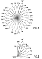
- Figure 8 illustrates one such example in which the cell 214 is divided into sectors 216a to 216z.
- Figure 8 shows the beam widths of the individual antenna sectors 62a to 62z. These beam widths may be less than 20°, for a 42GHz antenna.
- cell sectors 216f, 216g and 216m to 216q are shown in broken outline to indicate that their respective antenna sectors 62f,62g, and 62m to 62q are switched off.
- Such an increase in the power level in one sector 216b can be most conveniently provided by using reflective attenuators 11 in the switchable feeds to the antenna sectors 62a,62b,62c....
- the unwanted power output may be diverted from the switched off antenna sectors 62f,62g... etc to the antenna sector 62b by means of reflective attenuators 11 included in the switching matrix 60 (e.g as a modification of Figure 7).
- Figures 1, 2, 3, 4 and 8 illustrate a cellular system in which the transmitter T at the node of each cell is an omni-directional transmitter, i.e each of the antenna sectors 62a,62b,62c... transmits the same microwave signal at the same frequency and in phase into their respective cell sectors 216a,216b,216c... which together cover 360° around the transmitter T.
- the difference in the transmissions from the different antenna sectors 62a,62b,62c... is that from some sectors there may be no transmission, whereas from other sectors there is normal transmission, or the transmission power may be increased or decreased compared with the normal power level for the cell.
- Figure 9 illustrates a more advantageous cellular system in which each cell is edge-fed rather than centre-fed.
- Figure 9 shows the area of one cell, but the total system may comprise a large number of cells, covering a large total area.
- the transmitter T is directional and is located at an edge of the cell.
- the transmitting antenna is again divided into sectors e.g 62a to 62g so that the cell is also composed of sectors 216a to 216g.
- the normal transmission power levels vary across the antenna sectors 62a to 62g in order to provide total cell coverage.
- the normal power levels for the edge sectors 216a,216b,216g,216f are less than those for the inner sectors 216d,216c,216e.
- Figure 8 shows a transmission pattern in which there is no transmission in sectors 216f and 216g, either because no receiver R in these sectors is requesting transmission or because a microwave level detector D in these sectors is requesting no transmission.
- the transmission power has been increased so that the sectors increase in area to 216a' and 216b', thereby increasing the transmission signal level in the sectors 216a' and 216b' and/or increasing the range of these sectors.
- the increased power level in sectors 216a and 216b may be obtained conveniently using reflective attenuators 11 to divert the unwanted signal from antenna sectors 216f and 216g to antenna sectors 216a and 216b where it is wanted.
- a modification of the centre-fed cell of Figure 8 is also possible to form a hybrid centre-fed "edge-fed" type cell.
- some of the antenna sectors 62a,62b,62c... may transmit at different frequencies from the others.
- the signals carried out at different frequencies may be the same TV channel, or different TV channels (e.g from different oscillators 10 of TV1,TV2,TV3, etc in Figure 7) as requested by subscribing receivers R in their respective cells sectors 216a,216b,216c etc.
- Such an arrangement can be particularly advantageous for transmitting a minority-interest channel, or an individual video film, as requested by only one or two sector receivers R in the cell.
- the transmission patterns may be almost square so as to minimize the overlaps and to in fill the corners.
- each antenna sector is fixed.
- antennas which permit the transmitted beam directions to be shifted and steered.
- one cell sector transmission e.g 216a
- an active radio link 45,46 and/or a telephone line link 47,48 is used to provide the return channel from the monitor R,D to the transmitter T.
- a cellular system in accordance with the present invention may be designed to use passive transponding of the transmitted signal in a cell sector to promote a return channel, at least by a receiver R or detector D located close to the transmitter T.
Claims (10)
- Zellulares Mikrowellen-Videoverteilsystem mit einem Mikrowellensender (T) mit einer Sendeantenne (62) an einem Knotenpunkt (204, 206) einer Zelle (214) zum Übertragen eines Mikrowellensignals in dieser Zelle, und mit Teilnehmerempfängern (R) in der Zelle (214) zum Empfangen des in dieser Zelle gesendeten Mikrowellensignals, wobei die Sendeantenne (62) aus einzelnen Antennensektoren (62a, 62b, 62c) besteht zum Übertragen des Mikrowellensignals zu den verschiedenen Sektoren (216a, 216b, 216c) der Zelle (214), wobei die Antennensektoren (62a, 62b, 62c) einzeln ansteuerbar sind zum Ändern des Sendemusters in der Zelle (214), dadurch gekennzeichnet, dass ein betreffender Monitor (R, D) in jedem Sektor (216a, 216b, 216c) der Zelle (214) vorhanden ist zum Überwachen des Mikrowellensignals, das in diesem Sektor übertragen worden ist, und dass Mittel (49, 44, 49) vorgesehen sind zum Koppeln eines Ausgang (d) von dem Monitor (R, D) mit dem Sender (T) zur Steuerung des Mikrowellensignals, das zu diesem Sektor (216a, 216b, 216c) der Zelle (214) übertragen worden ist, und zwar von dem betreffenden Antennensektor (62a, 62b, 62c) in Reaktion auf den Ausgang (d) von dem Monitor (R, D) zum Minimieren der in den betreffenden Sektor (216a, 216b, 216c) eingesendeten Mikrowellensignalstärke.
- System nach Anspruch 1, dadurch gekennzeichnet, dass die Sendeantenne (62) innerhalb der Zelle (214) eine Rundstrahlantenne ist, und dass jeder Antennensektor (62a, 62b, 62c) eine Strahlbreite von weniger als 30 hat.
- System nach Anspruch 1, dadurch gekennzeichnet, dass die Sendeantenne (62) an der Peripherie der Zelle (214) vorgesehen ist, und jeder Antennensektor (62a, 62b, 62c) eine Strahlbreite von weniger als 10 hat.
- System nach einem der Ansprüche 1 bis 3, dadurch gekennzeichnet, dass jeder teilnehmende Empfänger (R) als Monitor in dem betreffenden Sektor (216a, 216b, 216c) der Zelle (214) funktioniert und Mittel (45, 46, 66; 47, 48) aufweist zum Rückkoppeln eines Antragssignals zu dem betreffenden Sender (T) zum Beantragen einer Übertragung des Mikrowellensignals zu diesem Sektor (216a, 216b, 216c) der Zelle (214) wenn eine derartige Übertragung von dem teilnehmenden Empfänger (R) beantragt wird.
- System nach Anspruch 4, dadurch gekennzeichnet, dass kein Mikrowellensignal zu einem Sektor (216a, 216b, 216c) der Zelle (214) übertragen wird, es sei denn, dass ein teilnehmender Empfänger (R) in diesem Sektor eine Übertragung des Mikrowellensignals zu diesem Sektor beantragt.
- System nach einem der Ansprüche 1 bis 5, dadurch gekennzeichnet, dass der Mikrowellenleistungsdetektor (D) in wenigstens einem Sektor (216a, 216b, 216c) der Zelle (214) vorhanden ist zum Funktionieren als Monitor in diesem Sektor, und dass der Mikrowellenleistungsdetektor (D) dazu dient, ein Antragssignal zu dem Sender (T) zu schaffen zum Beantragen einer Verringerung der Leistung des Mikrowellensignals, das diesem Sektor (216a, 216b, 216c) der Zelle zugeführt worden ist, wenn die Leistung des Mikrowellensignals, das von dem Mikrowellenleistungsdetektor (D) überwacht worden ist, einen vorbestimmten Pegel übersteigt.
- System nach einem der Ansprüche 1 bis 6, dadurch gekennzeichnet, dass die Antennensektoren (62a, 62b, 62c) einzeln steuerbar sind, und zwar durch die betreffenden Schaltmittel (60a, 60b, 60c) zum Ein- und Abschalten der Mikrowellensignale, die von jedem Antennensektor (62a, 62b, 62c) übertragen worden sind.
- System nach einem der Ansprüche 1 bis 7, gekennzeichnet durch eine Anzahl Zellen (214) und eine Anzahl der genannten Sender (T), wobei jeder der genannten Sender eine Antenne (62) hat, die an einem Knotenpunkt (204, 206) einer betreffenden Zelle (214) liegt, wobei die Mikrowellensignale, die von einem einzelnen Sender (T) übertragen worden sind, einen Kenncode für diesen Sender (T) enthalten, und wobei jeder der Monitoren (R, D) Detektionsmittel (Si) aufweist zum Detektieren und Benutzen dieses Kenncodes in dem Ausgang (d) für den betreffenden Antennensektor (62a, 62b, 62c).
- Anpassbarer Mikrowellensender (T) für ein zellulares Mikrowellen-Videoverteilsystem, wobei der Sender (T) eine Sendeantenne (62) an einem Knotenpunkt (204, 206) einer Zelle (214) aufweist zum Übertragen eines Mikrowellensignals zu Teilnehmerempfängern (R) in dieser Zelle (214), wobei die Sendeantenne (62) aus einzelnen Antennensektoren (62a, 62b, 62c) besteht zum Übertragen des Mikrowellensignals zu den verschiedenen Sektoren (216a, 216b, 216c) der Zelle (214), wobei die Antennensektoren (62a, 62b, 62c) einzeln steuerbar sind zum Ändern des Übertragungsmusters in der Zelle (214), dadurch gekennzeichnet, dass Mittel (66, 49) vorgesehen sind zum Empfangen eines Ausgangs (d) von einem betreffenden Monitor (R, D) in jedem Sektor (216a, 216b, 216c) der Zelle (214) und zur Steuerung des Mikrowellensignals, das zu diesem Sektor der Zelle (214) übertragen worden ist, und zwar von dem betreffenden Antennensektor (62a, 62b, 62c) in Reaktion auf den Ausgang (d) von dem Monitor (R, D) zum Minimieren der in den betreffenden Sektor (216a, 216b, 216c) eingesendeten Mikrowellensignalstärke.
- Sender nach Anspruch 9, dadurch gekennzeichnet, dass die Antennensektoren (62a, 62b, 62c) einzeln steuerbar sind durch die betreffenden Schaltmittel (60a, 60b, 60c) zum Ein- und Abschalten der Mikrowellensignale, die von jedem Antennensektor (62a, 62b, 62c) übertragen worden sind.
Applications Claiming Priority (3)
| Application Number | Priority Date | Filing Date | Title |
|---|---|---|---|
| GB9417318A GB9417318D0 (en) | 1994-08-27 | 1994-08-27 | Microwave cellular communications system and adaptable microwave transmitter |
| GB9417318 | 1994-08-27 | ||
| PCT/IB1995/000643 WO1996007285A1 (en) | 1994-08-27 | 1995-08-14 | Microwave video distribution system and adaptable microwave transmitter |
Publications (2)
| Publication Number | Publication Date |
|---|---|
| EP0726019A1 EP0726019A1 (de) | 1996-08-14 |
| EP0726019B1 true EP0726019B1 (de) | 2000-11-02 |
Family
ID=10760482
Family Applications (1)
| Application Number | Title | Priority Date | Filing Date |
|---|---|---|---|
| EP95926477A Expired - Lifetime EP0726019B1 (de) | 1994-08-27 | 1995-08-14 | Mikrowellenvideoverteilsystem und anpassbarer mikrowellensender |
Country Status (6)
| Country | Link |
|---|---|
| US (1) | US5920813A (de) |
| EP (1) | EP0726019B1 (de) |
| JP (1) | JPH09504932A (de) |
| DE (1) | DE69519280T2 (de) |
| GB (1) | GB9417318D0 (de) |
| WO (1) | WO1996007285A1 (de) |
Families Citing this family (22)
| Publication number | Priority date | Publication date | Assignee | Title |
|---|---|---|---|---|
| SE515776C2 (sv) * | 1996-01-26 | 2001-10-08 | Telia Ab | System för radiokommunikation vid korta avstånd mellan sändare och mottagare |
| EP0820194A1 (de) * | 1996-07-19 | 1998-01-21 | Telefonaktiebolaget Lm Ericsson | Methode und Anordnung für integrierte Funktelekommunikation über ein Kabelfernsehnetzwerk |
| KR100202502B1 (ko) * | 1996-12-30 | 1999-06-15 | 정장호 | 이동통신시스템 기지국의 시험회로 |
| WO1998042150A2 (en) * | 1997-03-14 | 1998-09-24 | At & T Corp. | Downlink smart antennas for is-54/is-136 tdma systems |
| FR2762178B1 (fr) * | 1997-04-14 | 2001-10-05 | Thomson Multimedia Sa | Procede et systeme de distribution de services video |
| FR2764140B1 (fr) * | 1997-05-28 | 1999-08-06 | Armand Levy | Procede de communication entre une station de base a n antennes et un mobile et station de base permettant de mettre en oeuvre ce procede |
| US6952585B1 (en) * | 1997-11-19 | 2005-10-04 | Ericsson Inc. | Multi-channel communication system for wireless local loop communication |
| US6011979A (en) * | 1997-12-18 | 2000-01-04 | U S West, Inc. | Method for selecting an amplifier for use in a personal communication service base station |
| FR2776145B1 (fr) * | 1998-03-13 | 2000-07-28 | Thomson Multimedia Sa | Systeme et procede de transmission de signaux |
| US6236866B1 (en) * | 1998-05-15 | 2001-05-22 | Raytheon Company | Adaptive antenna pattern control for a multiple access communication system |
| JP4087023B2 (ja) * | 1998-09-22 | 2008-05-14 | シャープ株式会社 | ミリ波帯信号送受信システムおよびミリ波帯信号送受信システムを具備した家屋 |
| SE517197C2 (sv) * | 1999-04-15 | 2002-05-07 | Ericsson Telefon Ab L M | Adaptiv sektorindelning |
| US6658269B1 (en) | 1999-10-01 | 2003-12-02 | Raytheon Company | Wireless communications system |
| US6762680B2 (en) * | 1999-12-02 | 2004-07-13 | Dieter W. Blum | Method and apparatus for electrodynamic intrusion detection |
| GB2364478A (en) * | 2000-06-30 | 2002-01-23 | Nokia Oy Ab | Cellular broadcast system responsive to distribution of demand |
| US7603127B2 (en) * | 2001-10-12 | 2009-10-13 | Airvana, Inc. | Boosting a signal-to-interference ratio of a mobile station |
| ATE323953T1 (de) * | 2002-01-23 | 2006-05-15 | Siemens Schweiz Ag | Mobilfunkantennenanlage mit einstellbarem richtverhalten |
| US7742788B2 (en) * | 2002-10-01 | 2010-06-22 | Motorola, Inc. | Method and apparatus for using switched multibeam antennas in a multiple access communication system |
| US7499708B2 (en) * | 2004-09-09 | 2009-03-03 | Telcom Ventures, L.L.C. | Millimeter microwave point-to-multipoint broadcasting systems, components and methods that monitor and rebroadcast data packets |
| US20060098580A1 (en) * | 2004-11-08 | 2006-05-11 | Qinghua Li | Apparatus and method capable of beam forming adjustments |
| US7596108B2 (en) * | 2005-05-31 | 2009-09-29 | Telcom Ventures, L.L.C. | Digital data broadcasting systems, methods and components that selectively rebroadcast data packets based on analysis of propagation characteristics |
| KR101517170B1 (ko) | 2009-09-29 | 2015-05-04 | 삼성전자주식회사 | 다중 안테나 시스템에서 전력 소모를 줄이기 위한 장치 및 방법 |
Family Cites Families (16)
| Publication number | Priority date | Publication date | Assignee | Title |
|---|---|---|---|---|
| US4730310A (en) * | 1985-05-03 | 1988-03-08 | American Telephone And Telegraph Company | Terrestrial communications system |
| FR2592256B1 (fr) * | 1985-12-20 | 1988-02-12 | Trt Telecom Radio Electr | Dispositif d'asservissement de la puissance d'emission d'un faisceau hertzien |
| US4750036A (en) * | 1986-05-14 | 1988-06-07 | Radio Telcom & Technology, Inc. | Interactive television and data transmission system |
| US4747160A (en) * | 1987-03-13 | 1988-05-24 | Suite 12 Group | Low power multi-function cellular television system |
| US4845504A (en) * | 1987-04-08 | 1989-07-04 | M/A-Com, Inc. | Mobile radio network for nationwide communications |
| SE8803094D0 (sv) * | 1988-09-05 | 1988-09-05 | Joakim Nelson | Ytteckande tradlosa telekommunikationssystem med tids, frekvens och rymdstyrning |
| US5432780A (en) * | 1988-09-12 | 1995-07-11 | Motorola, Inc. | High capacity sectorized cellular communication system |
| US5021801A (en) * | 1989-09-05 | 1991-06-04 | Motorola, Inc. | Antenna switching system |
| WO1991007043A1 (en) * | 1989-11-07 | 1991-05-16 | Pactel Corporation | Improved microcell system for cellular telephone systems |
| US5276907A (en) * | 1991-01-07 | 1994-01-04 | Motorola Inc. | Method and apparatus for dynamic distribution of a communication channel load in a cellular radio communication system |
| US5212830A (en) * | 1991-05-31 | 1993-05-18 | International Mobile Machines Corporation | Radio frequency communications system |
| DE4134357A1 (de) * | 1991-10-17 | 1993-04-22 | Standard Elektrik Lorenz Ag | Nachrichtenuebertragungssystem |
| SE514000C2 (sv) * | 1992-04-29 | 2000-12-11 | Telia Ab | Förfarande och anordning för att minska fädningen mellan basstation och mobila enheter |
| JPH06268574A (ja) * | 1993-03-11 | 1994-09-22 | Hitachi Ltd | セルラ移動通信システム |
| GB2281007B (en) * | 1993-08-12 | 1998-04-15 | Northern Telecom Ltd | Base station antenna arrangement |
| DE69516512T2 (de) * | 1994-03-17 | 2000-11-09 | Endlink Inc | Sektorisiertes mehrzweck cellulares funkubertragungssystem |
-
1994
- 1994-08-27 GB GB9417318A patent/GB9417318D0/en active Pending
-
1995
- 1995-08-14 WO PCT/IB1995/000643 patent/WO1996007285A1/en active IP Right Grant
- 1995-08-14 DE DE69519280T patent/DE69519280T2/de not_active Expired - Fee Related
- 1995-08-14 JP JP8508586A patent/JPH09504932A/ja not_active Ceased
- 1995-08-14 EP EP95926477A patent/EP0726019B1/de not_active Expired - Lifetime
- 1995-08-28 US US08/520,280 patent/US5920813A/en not_active Expired - Fee Related
Also Published As
| Publication number | Publication date |
|---|---|
| WO1996007285A1 (en) | 1996-03-07 |
| EP0726019A1 (de) | 1996-08-14 |
| US5920813A (en) | 1999-07-06 |
| GB9417318D0 (en) | 1994-10-19 |
| DE69519280T2 (de) | 2001-04-26 |
| DE69519280D1 (de) | 2000-12-07 |
| JPH09504932A (ja) | 1997-05-13 |
Similar Documents
| Publication | Publication Date | Title |
|---|---|---|
| EP0726019B1 (de) | Mikrowellenvideoverteilsystem und anpassbarer mikrowellensender | |
| CA1333089C (en) | Low power multi-function cellular television system | |
| US5953670A (en) | Arrangement for providing cellular communication via a CATV network | |
| US6006069A (en) | Point-to-multipoint communications system | |
| JP4323311B2 (ja) | 自由空間ミリ波中継線によるセルラー電話システム | |
| US6304762B1 (en) | Point to multipoint communication system with subsectored upstream antennas | |
| US8472879B2 (en) | System, apparatus and method for single-channel or multi-channel terrestrial communication | |
| US6445926B1 (en) | Use of sectorized polarization diversity as a means of increasing capacity in cellular wireless systems | |
| US6112056A (en) | Low power, short range point-to-multipoint communications system | |
| JP3933699B2 (ja) | 同一バンドを用いてのデジタル信号とアナログ信号の送信 | |
| US6141557A (en) | LMDS system having cell-site diversity and adaptability | |
| US20110109501A1 (en) | Automated beam peaking satellite ground terminal | |
| CA2185711A1 (en) | Sectorized multi-function cellular radio communication system | |
| US5594937A (en) | System for the transmission and reception of directional radio signals utilizing a gigahertz implosion concept | |
| GB2300549A (en) | Cellular comms using catv | |
| JPH0576213B2 (de) | ||
| WO1997046040A2 (en) | Lmds system having cell-site diversity and adaptability | |
| MURATA et al. | Portable digital satellite news gathering (SNG) RF terminal using a flat antenna | |
| Perlow | Microwave video distribution: 28-and 42-GHz | |
| Hayter et al. | 40 GHZ MVDS parameters and planning standards (multipoint video distribution systems) | |
| Wise et al. | MMDS in Hong Kong: wharf cable's initial cable television distribution system | |
| CA2270779A1 (en) | Use of sectorized polarization diversity as a means of increasing capacity in cellular wireless systems | |
| Laflin et al. | The provision of circuits to outside broadcast locations using spectrum within the UHF broadcasting bands | |
| Harris | The UK technical and regulatory framework established for analogue multipoint video distribution systems at 40 GHz |
Legal Events
| Date | Code | Title | Description |
|---|---|---|---|
| PUAI | Public reference made under article 153(3) epc to a published international application that has entered the european phase |
Free format text: ORIGINAL CODE: 0009012 |
|
| AK | Designated contracting states |
Kind code of ref document: A1 Designated state(s): DE FR GB |
|
| 17P | Request for examination filed |
Effective date: 19960909 |
|
| 17Q | First examination report despatched |
Effective date: 19990610 |
|
| GRAG | Despatch of communication of intention to grant |
Free format text: ORIGINAL CODE: EPIDOS AGRA |
|
| 17Q | First examination report despatched |
Effective date: 19990610 |
|
| GRAG | Despatch of communication of intention to grant |
Free format text: ORIGINAL CODE: EPIDOS AGRA |
|
| GRAH | Despatch of communication of intention to grant a patent |
Free format text: ORIGINAL CODE: EPIDOS IGRA |
|
| GRAH | Despatch of communication of intention to grant a patent |
Free format text: ORIGINAL CODE: EPIDOS IGRA |
|
| GRAA | (expected) grant |
Free format text: ORIGINAL CODE: 0009210 |
|
| AK | Designated contracting states |
Kind code of ref document: B1 Designated state(s): DE FR GB |
|
| REF | Corresponds to: |
Ref document number: 69519280 Country of ref document: DE Date of ref document: 20001207 |
|
| ET | Fr: translation filed | ||
| PLBE | No opposition filed within time limit |
Free format text: ORIGINAL CODE: 0009261 |
|
| STAA | Information on the status of an ep patent application or granted ep patent |
Free format text: STATUS: NO OPPOSITION FILED WITHIN TIME LIMIT |
|
| 26N | No opposition filed | ||
| REG | Reference to a national code |
Ref country code: GB Ref legal event code: IF02 |
|
| PGFP | Annual fee paid to national office [announced via postgrant information from national office to epo] |
Ref country code: FR Payment date: 20030827 Year of fee payment: 9 |
|
| PGFP | Annual fee paid to national office [announced via postgrant information from national office to epo] |
Ref country code: GB Payment date: 20030829 Year of fee payment: 9 |
|
| PGFP | Annual fee paid to national office [announced via postgrant information from national office to epo] |
Ref country code: DE Payment date: 20031015 Year of fee payment: 9 |
|
| PG25 | Lapsed in a contracting state [announced via postgrant information from national office to epo] |
Ref country code: GB Free format text: LAPSE BECAUSE OF NON-PAYMENT OF DUE FEES Effective date: 20040814 |
|
| PG25 | Lapsed in a contracting state [announced via postgrant information from national office to epo] |
Ref country code: DE Free format text: LAPSE BECAUSE OF NON-PAYMENT OF DUE FEES Effective date: 20050301 |
|
| GBPC | Gb: european patent ceased through non-payment of renewal fee |
Effective date: 20040814 |
|
| PG25 | Lapsed in a contracting state [announced via postgrant information from national office to epo] |
Ref country code: FR Free format text: LAPSE BECAUSE OF NON-PAYMENT OF DUE FEES Effective date: 20050429 |
|
| REG | Reference to a national code |
Ref country code: FR Ref legal event code: ST |