EP0725711B1 - Method and apparatus for cutting piled fabric - Google Patents
Method and apparatus for cutting piled fabric Download PDFInfo
- Publication number
- EP0725711B1 EP0725711B1 EP94928549A EP94928549A EP0725711B1 EP 0725711 B1 EP0725711 B1 EP 0725711B1 EP 94928549 A EP94928549 A EP 94928549A EP 94928549 A EP94928549 A EP 94928549A EP 0725711 B1 EP0725711 B1 EP 0725711B1
- Authority
- EP
- European Patent Office
- Prior art keywords
- cutting
- fabric
- pile elements
- cutting blade
- support frame
- Prior art date
- Legal status (The legal status is an assumption and is not a legal conclusion. Google has not performed a legal analysis and makes no representation as to the accuracy of the status listed.)
- Expired - Lifetime
Links
- 238000005520 cutting process Methods 0.000 title claims description 184
- 239000004744 fabric Substances 0.000 title claims description 134
- 238000000034 method Methods 0.000 title claims description 30
- 238000005452 bending Methods 0.000 claims description 20
- 238000010008 shearing Methods 0.000 claims description 9
- 239000007787 solid Substances 0.000 claims description 7
- 238000010408 sweeping Methods 0.000 claims description 3
- 230000000694 effects Effects 0.000 description 10
- 230000000712 assembly Effects 0.000 description 6
- 238000000429 assembly Methods 0.000 description 6
- 239000000463 material Substances 0.000 description 4
- 239000011800 void material Substances 0.000 description 4
- 229910000639 Spring steel Inorganic materials 0.000 description 3
- 230000008520 organization Effects 0.000 description 3
- 230000008901 benefit Effects 0.000 description 2
- 238000006073 displacement reaction Methods 0.000 description 2
- 239000011159 matrix material Substances 0.000 description 2
- 238000012986 modification Methods 0.000 description 2
- 230000004048 modification Effects 0.000 description 2
- 230000008447 perception Effects 0.000 description 2
- 230000008569 process Effects 0.000 description 2
- 229910000746 Structural steel Inorganic materials 0.000 description 1
- 230000015556 catabolic process Effects 0.000 description 1
- 239000002131 composite material Substances 0.000 description 1
- 230000006835 compression Effects 0.000 description 1
- 238000007906 compression Methods 0.000 description 1
- 238000006731 degradation reaction Methods 0.000 description 1
- 230000008030 elimination Effects 0.000 description 1
- 238000003379 elimination reaction Methods 0.000 description 1
- 238000009434 installation Methods 0.000 description 1
- 230000013011 mating Effects 0.000 description 1
- 230000007246 mechanism Effects 0.000 description 1
- 238000004064 recycling Methods 0.000 description 1
- 230000000717 retained effect Effects 0.000 description 1
- 238000009732 tufting Methods 0.000 description 1
- 238000009941 weaving Methods 0.000 description 1
Images



Classifications
-
- B—PERFORMING OPERATIONS; TRANSPORTING
- B26—HAND CUTTING TOOLS; CUTTING; SEVERING
- B26D—CUTTING; DETAILS COMMON TO MACHINES FOR PERFORATING, PUNCHING, CUTTING-OUT, STAMPING-OUT OR SEVERING
- B26D1/00—Cutting through work characterised by the nature or movement of the cutting member or particular materials not otherwise provided for; Apparatus or machines therefor; Cutting members therefor
- B26D1/01—Cutting through work characterised by the nature or movement of the cutting member or particular materials not otherwise provided for; Apparatus or machines therefor; Cutting members therefor involving a cutting member which does not travel with the work
- B26D1/04—Cutting through work characterised by the nature or movement of the cutting member or particular materials not otherwise provided for; Apparatus or machines therefor; Cutting members therefor involving a cutting member which does not travel with the work having a linearly-movable cutting member
- B26D1/06—Cutting through work characterised by the nature or movement of the cutting member or particular materials not otherwise provided for; Apparatus or machines therefor; Cutting members therefor involving a cutting member which does not travel with the work having a linearly-movable cutting member wherein the cutting member reciprocates
- B26D1/08—Cutting through work characterised by the nature or movement of the cutting member or particular materials not otherwise provided for; Apparatus or machines therefor; Cutting members therefor involving a cutting member which does not travel with the work having a linearly-movable cutting member wherein the cutting member reciprocates of the guillotine type
- B26D1/09—Cutting through work characterised by the nature or movement of the cutting member or particular materials not otherwise provided for; Apparatus or machines therefor; Cutting members therefor involving a cutting member which does not travel with the work having a linearly-movable cutting member wherein the cutting member reciprocates of the guillotine type with a plurality of cutting members
-
- B—PERFORMING OPERATIONS; TRANSPORTING
- B26—HAND CUTTING TOOLS; CUTTING; SEVERING
- B26F—PERFORATING; PUNCHING; CUTTING-OUT; STAMPING-OUT; SEVERING BY MEANS OTHER THAN CUTTING
- B26F1/00—Perforating; Punching; Cutting-out; Stamping-out; Apparatus therefor
- B26F1/38—Cutting-out; Stamping-out
- B26F1/40—Cutting-out; Stamping-out using a press, e.g. of the ram type
-
- D—TEXTILES; PAPER
- D06—TREATMENT OF TEXTILES OR THE LIKE; LAUNDERING; FLEXIBLE MATERIALS NOT OTHERWISE PROVIDED FOR
- D06H—MARKING, INSPECTING, SEAMING OR SEVERING TEXTILE MATERIALS
- D06H7/00—Apparatus or processes for cutting, or otherwise severing, specially adapted for the cutting, or otherwise severing, of textile materials
-
- Y—GENERAL TAGGING OF NEW TECHNOLOGICAL DEVELOPMENTS; GENERAL TAGGING OF CROSS-SECTIONAL TECHNOLOGIES SPANNING OVER SEVERAL SECTIONS OF THE IPC; TECHNICAL SUBJECTS COVERED BY FORMER USPC CROSS-REFERENCE ART COLLECTIONS [XRACs] AND DIGESTS
- Y10—TECHNICAL SUBJECTS COVERED BY FORMER USPC
- Y10T—TECHNICAL SUBJECTS COVERED BY FORMER US CLASSIFICATION
- Y10T83/00—Cutting
- Y10T83/04—Processes
- Y10T83/0405—With preparatory or simultaneous ancillary treatment of work
- Y10T83/0419—By distorting within elastic limit
- Y10T83/0433—By flexing around or by tool
-
- Y—GENERAL TAGGING OF NEW TECHNOLOGICAL DEVELOPMENTS; GENERAL TAGGING OF CROSS-SECTIONAL TECHNOLOGIES SPANNING OVER SEVERAL SECTIONS OF THE IPC; TECHNICAL SUBJECTS COVERED BY FORMER USPC CROSS-REFERENCE ART COLLECTIONS [XRACs] AND DIGESTS
- Y10—TECHNICAL SUBJECTS COVERED BY FORMER USPC
- Y10T—TECHNICAL SUBJECTS COVERED BY FORMER US CLASSIFICATION
- Y10T83/00—Cutting
- Y10T83/04—Processes
- Y10T83/06—Blanking
-
- Y—GENERAL TAGGING OF NEW TECHNOLOGICAL DEVELOPMENTS; GENERAL TAGGING OF CROSS-SECTIONAL TECHNOLOGIES SPANNING OVER SEVERAL SECTIONS OF THE IPC; TECHNICAL SUBJECTS COVERED BY FORMER USPC CROSS-REFERENCE ART COLLECTIONS [XRACs] AND DIGESTS
- Y10—TECHNICAL SUBJECTS COVERED BY FORMER USPC
- Y10T—TECHNICAL SUBJECTS COVERED BY FORMER US CLASSIFICATION
- Y10T83/00—Cutting
- Y10T83/444—Tool engages work during dwell of intermittent workfeed
-
- Y—GENERAL TAGGING OF NEW TECHNOLOGICAL DEVELOPMENTS; GENERAL TAGGING OF CROSS-SECTIONAL TECHNOLOGIES SPANNING OVER SEVERAL SECTIONS OF THE IPC; TECHNICAL SUBJECTS COVERED BY FORMER USPC CROSS-REFERENCE ART COLLECTIONS [XRACs] AND DIGESTS
- Y10—TECHNICAL SUBJECTS COVERED BY FORMER USPC
- Y10T—TECHNICAL SUBJECTS COVERED BY FORMER US CLASSIFICATION
- Y10T83/00—Cutting
- Y10T83/748—With work immobilizer
- Y10T83/7487—Means to clamp work
-
- Y—GENERAL TAGGING OF NEW TECHNOLOGICAL DEVELOPMENTS; GENERAL TAGGING OF CROSS-SECTIONAL TECHNOLOGIES SPANNING OVER SEVERAL SECTIONS OF THE IPC; TECHNICAL SUBJECTS COVERED BY FORMER USPC CROSS-REFERENCE ART COLLECTIONS [XRACs] AND DIGESTS
- Y10—TECHNICAL SUBJECTS COVERED BY FORMER USPC
- Y10T—TECHNICAL SUBJECTS COVERED BY FORMER US CLASSIFICATION
- Y10T83/00—Cutting
- Y10T83/869—Means to drive or to guide tool
- Y10T83/8736—Sequential cutting motions
-
- Y—GENERAL TAGGING OF NEW TECHNOLOGICAL DEVELOPMENTS; GENERAL TAGGING OF CROSS-SECTIONAL TECHNOLOGIES SPANNING OVER SEVERAL SECTIONS OF THE IPC; TECHNICAL SUBJECTS COVERED BY FORMER USPC CROSS-REFERENCE ART COLLECTIONS [XRACs] AND DIGESTS
- Y10—TECHNICAL SUBJECTS COVERED BY FORMER USPC
- Y10T—TECHNICAL SUBJECTS COVERED BY FORMER US CLASSIFICATION
- Y10T83/00—Cutting
- Y10T83/869—Means to drive or to guide tool
- Y10T83/8737—With tool positioning means synchronized with cutting stroke
-
- Y—GENERAL TAGGING OF NEW TECHNOLOGICAL DEVELOPMENTS; GENERAL TAGGING OF CROSS-SECTIONAL TECHNOLOGIES SPANNING OVER SEVERAL SECTIONS OF THE IPC; TECHNICAL SUBJECTS COVERED BY FORMER USPC CROSS-REFERENCE ART COLLECTIONS [XRACs] AND DIGESTS
- Y10—TECHNICAL SUBJECTS COVERED BY FORMER USPC
- Y10T—TECHNICAL SUBJECTS COVERED BY FORMER US CLASSIFICATION
- Y10T83/00—Cutting
- Y10T83/869—Means to drive or to guide tool
- Y10T83/8737—With tool positioning means synchronized with cutting stroke
- Y10T83/874—Straight line positioning
-
- Y—GENERAL TAGGING OF NEW TECHNOLOGICAL DEVELOPMENTS; GENERAL TAGGING OF CROSS-SECTIONAL TECHNOLOGIES SPANNING OVER SEVERAL SECTIONS OF THE IPC; TECHNICAL SUBJECTS COVERED BY FORMER USPC CROSS-REFERENCE ART COLLECTIONS [XRACs] AND DIGESTS
- Y10—TECHNICAL SUBJECTS COVERED BY FORMER USPC
- Y10T—TECHNICAL SUBJECTS COVERED BY FORMER US CLASSIFICATION
- Y10T83/00—Cutting
- Y10T83/869—Means to drive or to guide tool
- Y10T83/8748—Tool displaceable to inactive position [e.g., for work loading]
-
- Y—GENERAL TAGGING OF NEW TECHNOLOGICAL DEVELOPMENTS; GENERAL TAGGING OF CROSS-SECTIONAL TECHNOLOGIES SPANNING OVER SEVERAL SECTIONS OF THE IPC; TECHNICAL SUBJECTS COVERED BY FORMER USPC CROSS-REFERENCE ART COLLECTIONS [XRACs] AND DIGESTS
- Y10—TECHNICAL SUBJECTS COVERED BY FORMER USPC
- Y10T—TECHNICAL SUBJECTS COVERED BY FORMER US CLASSIFICATION
- Y10T83/00—Cutting
- Y10T83/869—Means to drive or to guide tool
- Y10T83/8748—Tool displaceable to inactive position [e.g., for work loading]
- Y10T83/8749—By pivotal motion
-
- Y—GENERAL TAGGING OF NEW TECHNOLOGICAL DEVELOPMENTS; GENERAL TAGGING OF CROSS-SECTIONAL TECHNOLOGIES SPANNING OVER SEVERAL SECTIONS OF THE IPC; TECHNICAL SUBJECTS COVERED BY FORMER USPC CROSS-REFERENCE ART COLLECTIONS [XRACs] AND DIGESTS
- Y10—TECHNICAL SUBJECTS COVERED BY FORMER USPC
- Y10T—TECHNICAL SUBJECTS COVERED BY FORMER US CLASSIFICATION
- Y10T83/00—Cutting
- Y10T83/869—Means to drive or to guide tool
- Y10T83/8821—With simple rectilinear reciprocating motion only
- Y10T83/8828—Plural tools with same drive means
- Y10T83/8831—Plural distinct cutting edges on same support
-
- Y—GENERAL TAGGING OF NEW TECHNOLOGICAL DEVELOPMENTS; GENERAL TAGGING OF CROSS-SECTIONAL TECHNOLOGIES SPANNING OVER SEVERAL SECTIONS OF THE IPC; TECHNICAL SUBJECTS COVERED BY FORMER USPC CROSS-REFERENCE ART COLLECTIONS [XRACs] AND DIGESTS
- Y10—TECHNICAL SUBJECTS COVERED BY FORMER USPC
- Y10T—TECHNICAL SUBJECTS COVERED BY FORMER US CLASSIFICATION
- Y10T83/00—Cutting
- Y10T83/929—Tool or tool with support
- Y10T83/9411—Cutting couple type
- Y10T83/9447—Shear type
Definitions
- the present invention relates generally to an apparatus and method for cutting fabrics and more particularly piled fabric sections such as carpet tiles, such that the juncture between the fabric sections is substantially unidentifiable when they are placed in abutting relation to one another across a surface to be covered.
- Piled fabrics such as for example carpets, may be manufactured in numerous ways such as by weaving, tufting, needling or bonding. In each method the pile is secured in some manner to a base layer thereby forming a composite structure comprising a piling portion and a base portion.
- the base is generally substantially solid yet flexible in nature and typically comprises a bonding matrix in combination with a backing material.
- the fabric will comprise generally a piling portion having a multiplicity of pile elements and some type of stable base portion to which the pile elements are attached in an outwardly extending generally perpendicular fashion. Accordingly, the surface of the base adjacent to the outwardly extending pile elements forms a boundary between the piling and base portions. Above this boundary the pile elements may be bent rather freely.
- any bending of a pile element away from a perpendicular orientation with respect to the boundary surface of the base will tend to bring the pile element towards the base portion of the fabric.
- the bending of one element will lead to the bending of adjacent elements in the direction of the applied force.
- carpet tiles So as to facilitate ease of handling during transportation and installation, piled fabrics such as carpet are often formed into easily handled modular sections referred to generally as carpet tiles. These tiles are typically cut into discrete elements from a broad loom of piled fabric having the characteristics described above.
- the tiles are typically of a rectangular shape and are preferably substantially square so as to permit them to be laid side by side in abutting relation across a surface to be covered.
- a straight cut by means of a rotary blade or similar device may tend to leave half cut tufts and/or missing tufts along the edge of the tile. These half cut and missing tufts may give rise to a substantial degree of asymmetry from tile to tile. Furthermore, a straight cut leaving such half cut and missing tufts may give rise to voids at the juncture between the tiles installed across a surface to be covered. In the past, these problems have been addressed by cutting the edges of the tile on a chamfer, thereby generating a substantially uniform beveled appearance at the edges of the individual tiles.
- the height of the piling immediately adjacent to the edge of each tile is typically less than that existing across the rest of the tile. Moreover, this feature is replicated from tile to tile such that when the tiles are brought into abutting relation with one another across a surface to be covered, a visible seam is formed at the abutting interface between the individual tiles.
- an apparatus for use in the cutting of piled fabric into sections such as carpet squares comprises a frame, a bending assembly for bending a portion of piling elements away from the normal vertical orientation with respect to the base of the fabric along a line to be cut, a cutting blade for cutting the fabric through a portion of the bent piling elements and fabric base and means for powering the bending and cutting operations.
- a method of cutting piled fabrics into sections such as carpet tiles.
- the method comprises the steps of bending the piling elements of the fabric downward toward the fabric base along a line to be cut and thereafter cutting through a portion of the bent piling elements and through the fabric base to form a two-sided cut.
- Such a cutting method has the effect of shearing the piling elements adjacent to one side of the cut while leaving the piling elements adjacent to the other side of the cut substantially unaltered.
- a cut fabric section such as a carpet tile.
- This fabric section is formed by downwardly bending piling elements away from the normal vertical orientation toward the base of the fabric along a line to be cut preferably toward the interior of the resultant tile and thereafter cutting through a portion of the bent elements and through the fabric base.
- the pile elements adjacent to one side of the cut are partially sheared, while the pile elements adjacent to the other side of the cut remain substantially unaltered.
- the section of fabric having the partially sheared pile elements is disposed of for recycling while the section having substantially unaltered pile elements is retained for use in abutting orientation with other sections cut in a similar manner.
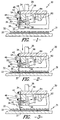
- FIG. 1 a partially cut-away side view of a potentially preferred embodiment of the basic apparatus 30 of the present invention is shown in FIG. 1.
- the apparatus 30 is useful in the cutting of piled fabric 31 having a piling portion 32 made up of individual pile elements and a substantially solid base portion 33.
- the base portion typically comprises a pile bonding matrix and some type of backing as is well known in the art.
- the basic apparatus 30 includes a frame 34 to which a cutting blade 36 is operatively connected.
- cutting blades is meant any means for generating a two-sided cut in the piled fabric 31.
- the frame 34 may be of any suitable geometry and may support a plurality of cutting blades 36 as discussed more fully below.
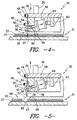
- the apparatus 30 is preferably moveable between the raised position illustrated in FIG. 1 and the lowered cutting position illustrated in FIGS. 2-4 by means of one or more driving rods 35 powered by appropriate power means such as a hydraulic or pneumatic cylinder (not shown).
- the cutting blade 36 includes an edge portion 37 formed at the intersection of a bevelled surface 38 and a substantially straight surface 39.
- the bevelled surface 38 may have an angle of between about 12 degrees and about 35 degrees. An angle of about 20 degrees may be preferred.
- the cutting blade 36 also preferably includes a body portion 40 which provides support and strength.
- the cutting blade 36 preferably extends in a lengthwise direction substantially traverse to the side view shown, thereby permitting a two-sided cut of up to eighteen inches or more to be made in the piled fabric 31.
- the cutting blade 36 is preferably connected to the frame 34 by means of a connective extension member 42.
- the connective extension member 42 preferably extends between a frame clamp 44 and a blade support member 46.
- the connective extension member 42 is preferably maintained in position between the frame clamp 44 and the frame 34 by means of connecting screws 48.
- a number of connecting screws 48 may extend across the length of the frame clamp 44 as may be necessary to support the connective extension member 42 clamped therein.
- the connective extension member 42 is also preferably secured to the blade support member 46 by means of connecting screws 50.
- the blade support member 46 is preferably formed of structural steel and has a substantially inverted L-shaped cross sectional configuration including a first leg 52 and a second leg 53.
- the first leg 52 has a width which is substantially equivalent to the width of the body portion 40 of the cutting blade 36 so as to effect a good mating relationship therebetween.
- the containment of the cutting blade 36 between the blade support member 46 and the connective extension member 42 is maintained by the tensioning of the connecting screws 50 which preferably extend through both the connective extension member 42 and the blade support member 46. While only a single connecting screw 50 is illustrated, it is to be understood that a number of such connecting screws 50 may be disposed across the length of the blade support member 46. By way of example only, it has been found that for a blade of 300 mm (12 inches) in length and having a width of 3.2 mm (0.125) inches, adequate support is provided by 11 connecting screws 50 disposed approximately every inch across the length of the blade support member 46.
- the connective extension member 42 is preferably disposed in abutting relation along one face of the body portion 40 of the cutting blade 36. As shown, this configuration gives rise to a substantially inverted U-shaped clamping structure formed by the connective extension member 42 and by the first and second legs 52, 53 of the blade support member 46.
- blade support member 46, the connective extension member 42 and the frame clamp 44 comprise a connective assembly for connecting the cutting blade 36 to the frame 34.
- suitable alternative connective assembly embodiments such as alternative clamping devices and the like may likewise be utilized and are considered within the scope of the present invention.
- one or more secondary support plates 54 are located adjacent to the connective extension member 42. As will be recognized, while a single secondary support plate 54 is shown in the side views of FIGS. 1-5, a number of such secondary support plates may be disposed at locations along the length of the connective extension member 42.
- the use of the secondary support plates 54 permits the connective extension member 42 to be formed of a relatively flexible material such as, for example, spring steel without compromising the securement of the cutting blade 36. As discussed in greater detail hereafter, the ability to use spring steel or similar flexible materials for the connective extension member 42 is important to the operation of the apparatus 30.
- the secondary support plates 54 are preferably connected to the rods 56 of power cylinders 58 at first pin joinder assemblies 60.
- the power cylinders 58 are, in turn, preferably supported to frame extension members 62 at second pin joinder assemblies 64. While a single power cylinder 58 is illustrated, it is intended that a plurality of power cylinders 58 may be disposed along the length of the cutting blade 36 as may be required. For example, it has been found that two power cylinders 58 each generating 3500 Newtons (125 pounds of force) are adequate for operation of a 300 mm (12 inch) cutting blade 36 (FIG. 16).
- FIGS. 1-5 The sequence of steps in the use of the apparatus of the present invention is shown in FIGS. 1-5.
- the apparatus 30 in the starting position (FIG. 1) the apparatus 30 is in the raised position away from the piled fabric 31 which is to be cut.
- the rods 56 of the power cylinders 58 are in the extended position thereby placing a bending moment on the connective extension member 42 and forcing the edge portion 37 of the cutting blade 36 away from a perpendicular orientation with respect to the piled fabric 31.
- the power cylinders 58 and associated cylinder rods 56 thus comprise a first power assembly for moving the edge portion 37 towards and away from the frame 34 such that the cutting blade 36 may be moved in a sweeping manner through the piling portion 32 of the piled fabric 31 as described below.
- the edge portion 37 of the cutting blade 36 is typically offset from its non extended position (FIG. 3) by a horizontal distance of between about 0.75 mm (0.03 inches) and about 6.35 mm (0.25 inches).
- a horizontal distance is applicable to any embodiment which may be utilized.
- a horizontal blade offset of approximately 3.2 mm (0.125 inches) may be preferred.
- the apparatus 30 is moved towards the piled fabric 31 by a second power assembly comprising the driving rods 35 powered by an appropriate power mechanism such as, for example, a hydraulic or pneumatic cylinder (not shown) as are well known to those of skill in the art.
- a second power assembly comprising the driving rods 35 powered by an appropriate power mechanism such as, for example, a hydraulic or pneumatic cylinder (not shown) as are well known to those of skill in the art.
- This movement of the apparatus 30 towards the piled fabric 31 preferably continues until the edge portion 37 of the cutting blade 36 is disposed within the piling portion 32 of the piled fabric 31. This movement, however, is terminated prior to the edge portion 37 of the cutting blade 36 reaching the upper surface of the substantially solid base portion 33.
- the rods 56 of the power cylinders 58 are retracted until the edge portion 37 of the cutting blade 36 is preferably substantially perpendicular to the base portion 33 of the piled fabric 31 (FIG. 3).
- the retraction of the rods 56 causes the cutting blade 36 to move through the piling portion 32 of the piled fabric 31, thereby tending to bend a portion of the pile elements in the direction of the applied force beneath the edge portion 37 downwardly toward the base 33 of the piled fabric 31 along a line to be cut.
- the pile elements are preferably bent toward the interior of the fabric section being cut, although it is to be understood that alternative bending practices as may occur to those of skill in the art may also be utilized.
- the power cylinders 58 acting through cylinder rods 56 and cutting blade 36 comprise an assembly for bending the pile elements in the manner described. It will, of course, be appreciated by those of skill in the art that alternative manual or mechanized bending assemblies which operate either in conjunction with a cutting blade or independently therefrom may likewise be utilized.
- the apparatus 30 is driven downward by the second power assembly, thereby forcing the edge portion 37 of the blade member 36 through the substantially solid base portion 33 of the piled fabric 31 in the manner illustrated in FIG. 4.
- the first and second power assemblies are preferably operative in conjunction with one another such that the edge portion 37 of the cutting blade 36 is moved through the piling portion of the piled fabric 31, thereby bending the pile elements in the direction of movement of the edge portion 37 prior to the edge portion 37 being driven through the fabric 31 to form a two sided cut therein.
- this cutting operation has the effect of shearing the individual pile elements bent beneath the cutting blade 36.
- This shearing of the bent pile elements is shown in FIG. 5, wherein the apparatus 30 has been moved away from the piled fabric 31 leaving a first fabric section 66 having a cut edge 67 and a second fabric section 68 having a cut edge 69.
- the cut edge 67 of the first fabric section 66 is formed by the substantially straight surface 39 on the cutting blade 36, while the cut edge 69 of the second fabric section 68 is formed by the beveled surface 38.
- the pile elements adjacent to the non-chamfered straight cut edge 67 of the first fabric section 66 remain substantially unaltered following the cutting operation.
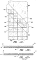
- the pile elements adjacent to the bevelled edge 69 of the second fabric section 68 are partially sheared by the beveled face 38 of the blade 36. Accordingly, the second fabric section 68 is recycled while the first fabric section 66 may be placed in abutting relation with other similarly cut fabric sections (FIG 20) without the occurrence of substantially visible seams between the individual sections.
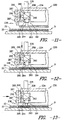
- FIGS. 6-10 A second embodiment of the apparatus of the present invention is shown in FIGS. 6-10.
- the apparatus 130 of the second embodiment includes a beveled blade 136 attached to a frame 134 by means of a hinged extension member 180.
- the beveled blade 136 is attached to the hinged extension member 180 by connective bolts 182.
- the hinged extension member 180 is, in turn, connected to the frame 134 at a hinge pin connection 184 so as to allow the partial rotation of the hinged extension member 180 and attached cutting blade 136 thereabout.
- the hinged extension member 180 is preferably connected to rods 156 of power cylinders 158 by means of pin connection members 160.
- the power cylinders 158 are, in turn, preferably connected to a frame extension member 162 by pin connection members 164, thereby providing a support structure for the operation thereof.
- the extension of the cylinder rods 156 forces the hinged extension member 180 and the attached cutting blade 136 away from the frame 134 about the hinge pin connection 184, thereby moving the cutting blade 136 from a position substantially perpendicular to the piled fabric to an orientation at an angle therewith and preferably providing a horizontal displacement of the cutting blade 136 of between about 0.75 mm (0.03 inches) and about 6.35 mm (0.25 inches).
- the apparatus 130 effects a cutting of the piled fabric 31 according to substantially the same method as described above in relation to Figs. 1-5 and the embodiment shown therein. Specifically, the frame 134 (with the blade member 136 in the extended position) is lowered into engagement with the piling portion 32 of the piled fabric 31 (FIG. 7). The rods 156 of the power cylinders 158 are thereafter retracted so as to move the edge portion 137 of the cutting blade 136 through the piling portion 32 of the piled fabric 31 (FIG. 8). The edge 137 of the cutting blade 136 is then driven through the base portion 33 of the piled fabric 31 (FIG. 9) so as to generate a two-sided cut wherein the pile elements adjacent to one side formed with a substantially straight non-chamfered cut are left substantially unaltered (FIG. 10).
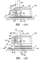
- FIGS. 11-15 Yet a third embodiment of the present invention is shown in FIGS. 11-15 wherein the apparatus 230 incorporates yet another configuration for moving the cutting blade 236 through the piling portion 32 of the pile fabric 31 to effect a substantially straight cut without altering the pile elements disposed adjacent thereto. It is to be appreciated that the apparatus 230 effects the cutting operation in substantially the same manner as described with respect to other embodiments. That is, the cutting blade 236 is moved into contact with the piling portion 32 of the fabric 31 (FIG. 12), is moved through the piling portion 32 to bend the pile elements along a line to be cut (FIG. 13) and is then driven through the base 33 of the piled fabric (FIG. 14) to form a two-sided cut (FIG. 15).
- the apparatus 230 includes a frame portion 234 and a bevelled cutting blade 236 connected to a support plate 285 by means of connective bolts 287.
- the support plate is, in turn, operatively connected to one or more cylinder rods 256 actuated by power cylinders 258.
- the cutting blade 236, support plate 285, piston rods 256 and power cylinders 258 are preferably aligned so as to impart to the cutting blade a substantially linear motion towards and away from the frame 234 as the piston rods 256 are extended and retracted. This linear movement preferably corresponds to a horizontal displacement of between about 0.75 mm (0.03 inches) and about 6.35 mm (0.25 inches).
- the power cylinders 258 are preferably supported against a leg portion 290 of the frame 234 adjacent to the support plate 285. As illustrated, the leg portion 290 is preferably provided with openings through which the piston rods 256 may act.
- the apparatus 30, 130, 230 also preferably includes a fabric securement assembly 291 such as illustrated in FIGS. 11-15.
- This fabric securement assembly is preferably attached to the frame 234 by means of one or more frame extensions 292 and includes a plate 293 connected to one or more biased rods 294 housed in cylinders 295.
- the plate 293 contacts and compresses the piling portion 32 of the piled fabric 31.
- the bias of the rod 294 is overcome, thereby driving the rods 294 into the cylinders 295 while at the same time applying an opposing force equal to the overcome bias to the piled fabric 31.
- FIGS. 11-15 illustrate a single rod 294 and cylinder 295
- a number of such rods and cylinders may be utilized.
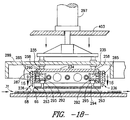
- the fabric securement assembly 291 may comprise a rod 294 and corresponding compression cylinder 295 located at each corner of the cutting unit (FIG. 18).
- the use of the fabric securement assembly 291 is in no way limited to any single embodiment of the apparatus of the present invention. Rather it is contemplated that the fabric securement assembly 291 is preferably used with any embodiment of the apparatus 30, 130, 230 of the present invention. Regardless of the embodiment, the distance between the edge of the cutting blade 36, 136, 236 and the edge of the plate 293 should be between about 0.05 mm (0.002 inches) and about 1.27 mm (0.05 inches) and preferably between about 0.25 mm (0.01 inches) and about 0.5 mm (0.02 inches) during the actual cutting operation (FIG. 14).
- FIGS. 16-17 A top plan view of one working configuration incorporating the embodiment of the apparatus 230 shown in FIGS. 11-15 is illustrated in FIGS. 16-17.
- four substantially identical cutting units 230a, 230b, 230c and 230d are arranged in a rectangular configuration mounted to a square frame 234 so as to enable four substantially identical cuts to be made in the piled fabric 31 thereby forming a substantially square tile section.
- Each of the substantially identical cutting units 230a - 230d includes two substantially identical power cylinders 258 as described above.
- the two power cylinders 258 on each of the cutting units operate in conjunction with one another to move the individual cutting blades 236 towards and away from the frame 234 by means of extension and retraction of their individual rods 256.
- the blades illustrated in FIG. 16 are in a position corresponding approximately to that shown in the side view of FIG. 11 wherein the rods 256 are in their extended position.
- the cutting blades 236 are moved towards the frame 234 as shown in FIG. 17.
- the cutting blades 236 are in a position corresponding approximately to that shown in FIG. 13.
- the support plates 285 and connected cutting blades travel on guide rods 270 between the extended position shown in FIG. 16 and the retracted position shown in FIG. 17. In the rectangular orientation illustrated in FIGS.
- acceptor ports 272 are oriented at each corner of the frame 234 to accept driving rods 235 which are used to move the frame 234 and cutting blades 236 downward as described above.
- the driving rods 235 may be powered by any appropriate power means such as, for example, a hydraulic or pneumatic master cylinder 297 applying equal force to each of the driving rods across an intermediate transfer plate 299 (FIG.18).
- the power cylinders 258 which actuate each of the individual cutting units 230a-230d are operable in a manner such that at least two, and preferably four, of the cutting units 230a-230d may be operated substantially simultaneously.
- FIGS. 16-17 is shown as incorporating the particular embodiment of the invention illustrated in FIGS. 11-15, all other potential embodiments of the invention may be configured in a similar manner so as to effect the cutting of given geometries of piled fabric such as carpet squares.
- a plurality of cutting units incorporating any illustrated or potential embodiment may be combined in a like described manner.
- the cutting units may be moved towards and away from the piled fabric 31 by power assemblies as are well known.
- power assemblies as are well known.
- one such power assembly is illustrated in FIG. 18 wherein the master cylinder 297 is used to drive the cutting blades 236 into contact with, and then through, the piled fabric 31.
- the master cylinder 297 is used to drive the cutting blades 236 into contact with, and then through, the piled fabric 31.
- FIG. 19 illustrates one possible organization for the use of the working configuration illustrated in Figs. 16-18.
- each rectangular configuration 400 made up of the basic cutting apparatus 30, 130, 230 may be arranged in a relative diagonal orientation along a suitable support structure 403 (FIG. 18).
- the support structure 403 provides a base from which the cutting blades may be moved toward and away from a moving broad loom of fabric 405 by appropriate power means in the manner described above.
- fabric sections such as carpet tiles 407 may be cut out as illustrated.
- the carpet tiles 407 correspond generally to the first fabric section 66 described above in relation to a single cut and accordingly have substantially straight edges with substantially unaltered pile elements adjacent thereto.
- the intermediate strip sections 409 correspond generally to the second fabric section 68 described previously in relation to a single cut and will exhibit bevelled edges with partially sheared pile elements at the outer perimeter.
- FIG. 20 The cut fabric produced by the apparatus and method of the present invention may be appreciated through comparison of Figs. 20 and 21.
- FIG. 20 two portions of piled fabric cut by the apparatus and method of the present invention are shown in abutting relationship along an interface 411. As shown, this interfacial relationship gives rise to no substantial irregularity in the profile of the piled fabric 31, since the piling portion 32 adjacent to the interface 411 has undergone no substantial shearing, thereby preventing the appearance of a substantially visible void.
- substantially visible void is meant a void which is readily apparent to the average human eye without external assistance of concentrated examination. This may be contrasted to the visible discontinuity at the interface 413 between portions of piled fabric cut according to present methods (FIG. 21) which is generally discernable by casual observation.
Landscapes
- Engineering & Computer Science (AREA)
- Life Sciences & Earth Sciences (AREA)
- Forests & Forestry (AREA)
- Mechanical Engineering (AREA)
- Textile Engineering (AREA)
- Treatment Of Fiber Materials (AREA)
Description
Claims (21)
- Apparatus for cutting of a piled fabric (31) having a piling portion (32) including pile elements and a base portion (33), the apparatus comprising: a vertically displaceable support frame (34); a cutting blade (36), said cutting blade (36) including a cutting portion (37) and a body portion wherein said cutting portion is formed by a bevelled surface (38) and a substantially straight surface (39); a connective assembly (42-54) connecting said cutting blade (36) to said support frame (34); a first power assembly (56-64) operatively connected to said cutting blade (36) for moving said cutting portion (37) of said cutting blade (36) towards and away from said support frame (34) along a substantially horizontal path across said base portion (33) of said piled fabric (31) such that said cutting portion (37) of said cutting blade (36) is moveable through the piling portion (32) of said piled fabric (31) substantially in the direction faced by said substantially straight surface (39); and a second power assembly (35) operatively connected to said support frame (34) for vertically moving said support frame (34) such that said cutting portion (37) of said cutting blade (36) is driven vertically through the base portion (33) of said piled fabric (31), said first power assembly (56-64) and said second power assembly (35) being operative such that said cutting blade (36) is moveable through the piling portion (32) of said piled fabric (31), thereby bending a portion of said pile elements beneath said cutting blade (36) prior to said cutting portion (37) of said cutting blade (36) being driven through said base portion (33) of said piled fabric (31) to form a two-sided cut (67,69) therein.
- The apparatus of Claim 1, wherein said cutting blade is connected to said support frame such that said beveled surface of said cutting blade faces outwardly from said support frame and said substantially straight surface of said cutting blade faces inwardly towards said support frame.
- The apparatus of Claim 2, wherein said cutting blade is operatively connected to said first power assembly such that said cutting blade is moveable by substantially linear motion towards and away from said support frame.
- The apparatus of claim 1, wherein said connective assembly connecting said cutting blade to said support frame comprises a flexible member extending between said cutting blade and said support frame.
- The apparatus of Claim 1, wherein said first power assembly comprises one or more pneumatic cylinders.
- The apparatus of Claim 1, wherein said second power assembly comprises at least one pneumatic cylinder.
- The apparatus of Claim 1, wherein said first power assembly comprises one or more hydraulic cylinders.
- The apparatus of Claim 1, wherein said second power assembly comprises at least one hydraulic cylinder.
- The apparatus of Claim 1, wherein said connective assembly connecting said cutting blade to said support frame comprises a hinged member.
- Apparatus for cutting of carpet fabric (31) having a piling portion (32) including a multiplicity of pile elements and a base portion (33), the apparatus comprising: a vertically displaceable support frame (234); a plurality of cutting blades (236), each of said cutting blades (236) having a cutting portion and a body portion, wherein said cutting portions of said cutting blades are each formed by a bevelled surface and a substantially straight surface; means (285-290) for connecting said cutting blades (236) to said support frame (234) such that said cutting portion of said cutting blades (236) is moveable towards and away from said support frame (234); cylinder means (258) operatively connected to said cutting blades (236) for moving said cutting portions of said cutting blades (236) along a path including a substantially horizontal component in the direction faced by said substantially straight surface; and power means (235) for vertically moving said support frame such that said cutting portions of said cutting blades (236) are driven vertically through said base portion (33) of said carpet fabric (31), said power means (235) and said cylinder means (258) being operative such that said cutting portions of said cutting blades (236) are moveable through the piling portion (32) of said carpet fabric (31) prior to said cutting portions of said cutting blades (236) being driven vertically through the base portion (33) of said carpet fabric (31).
- The apparatus of Claim 10, wherein four cutting blades form said plurality of blades and are connected to said support frame.
- The apparatus of Claim 11, wherein the four cutting blades are oriented to form a quadrangle.
- The apparatus of Claim 12, wherein the four cutting blades are connected to said support frame such that the beveled surfaces of said cutting blades face outwardly from said support frame and the substantially straight surfaces of said cutting blades face inwardly towards said support frame.
- A method for cutting a piled fabric having a piling portion including pile elements and an underlying base portion, the method comprising the steps of:(a) bending the pile elements downward toward the base portion of the piled fabric along a line to be cut; and(b) cutting through the pile elements bent in step (a) and the underlying base portion along said line to be cut, thereby partially shearing the pile elements bent downward toward the base portion in step (a) along said line to be cut such that a two-sided cut is formed through the piled fabric wherein the pile elements adjacent to one side of the two-sided cut remain substantially unaltered.
- A method for cutting a piled fabric having a piling portion including pile elements and a substantially solid base portion, the method comprising the steps of:(a) bringing a cutting blade having an edge portion and a body portion into contact with the piling portion of the piled fabric such that the edge portion of the cutting blade is disposed within said pile elements;(b) moving the edge portion of the cutting blade through the piling portion of the piled fabric in a path adjacent to the base portion of the fabric such that a portion of said pile elements are bent beneath the edge portion of the cutting blade towards the base portion of the piled fabric; and(c) driving the edge portion of the cutting blade through the pile elements bent in step (b) and the underlying base portion, thereby partially shearing the portion of said pile elements bent beneath the edge portion of the cutting blade and cutting through the underlying base portion such that a two-sided cut is formed through the pile elements and the base portion wherein the pile elements adjacent to one side of the two-sided cut remain substantially unsheared.
- The method of claim 15 wherein in step (b) the edge portion of the cutting blade is moved a distance of between about 0.75 mm (0.03 inches) and 6.35 mm (0.25 inches).
- A method for cutting a carpet tile from a carpet fabric having a piling portion including pile elements and a substantially solid base portion, the method comprising the steps of:(a) bringing a plurality of cutting blades, each including an edge, into contact with the piling portion of the carpet fabric such that the cutting edges of said plurality of cutting blades are disposed within said pile elements;(b) sweeping the edges of said plurality of cutting blades through the piling portion of the piled fabric such that a portion of said pile elements are bent beneath the edges of said plurality of cutting blades towards the base portion of the carpet fabric along a line to be cut; and(c) driving the edges of said plurality of cutting blades through the pile elements bent in step (b) and the underlying base portion, thereby forming a two-sided cut in the carpet fabric partially shearing the portion of said pile elements bent beneath said plurality of cutting blades without substantially altering the pile elements not bent beneath said plurality of cutting blades.
- The method of claim 17, wherein four cutting blades are utilized.
- The method of Claim 18, wherein the cutting blades are arranged in the form of a rectangle.
- A method for cutting a plurality of carpet tiles from a carpet fabric section including pile elements and a substantially solid base portion, the method comprising the steps of:(a) orienting a plurality of cutting units diagonally across the width of the carpet fabric section, each of said cutting units comprising a plurality of cutting blades, each cutting blade including an edge;(b) bringing said cutting units into engagement with said carpet fabric;(c) sweeping the edges of said cutting blades through the piling portion of the carpet fabric section such that a portion of said pile elements are bent beneath the edges of said of cutting blades along a line to be cut;(d) driving the edges of said of cutting blades through the pile elements bent in step (c) and the underlying base portion, thereby forming a two-sided cut in the carpet fabric by partially shearing the portion of said pile elements bent beneath said plurality of cutting blades;(e) retracting said cutting units from engagement with said carpet fabric; and(f) advancing said carpet fabric for further cutting.
- The method of Claim 20, wherein in step (b) each of said cutting units engage said carpet fabric simultaneously.
Applications Claiming Priority (3)
| Application Number | Priority Date | Filing Date | Title |
|---|---|---|---|
| US11005593A | 1993-08-30 | 1993-08-30 | |
| US110055 | 1993-08-30 | ||
| PCT/US1994/009575 WO1995006548A1 (en) | 1993-08-30 | 1994-08-26 | Method and apparatus for cutting piled fabric |
Publications (3)
| Publication Number | Publication Date |
|---|---|
| EP0725711A1 EP0725711A1 (en) | 1996-08-14 |
| EP0725711A4 EP0725711A4 (en) | 1997-02-12 |
| EP0725711B1 true EP0725711B1 (en) | 1999-12-08 |
Family
ID=22331000
Family Applications (1)
| Application Number | Title | Priority Date | Filing Date |
|---|---|---|---|
| EP94928549A Expired - Lifetime EP0725711B1 (en) | 1993-08-30 | 1994-08-26 | Method and apparatus for cutting piled fabric |
Country Status (5)
| Country | Link |
|---|---|
| US (2) | US5979278A (en) |
| EP (1) | EP0725711B1 (en) |
| AU (1) | AU684109B2 (en) |
| DE (1) | DE69422056D1 (en) |
| WO (1) | WO1995006548A1 (en) |
Cited By (1)
| Publication number | Priority date | Publication date | Assignee | Title |
|---|---|---|---|---|
| US10443188B2 (en) | 2016-05-25 | 2019-10-15 | Apache Mills, Inc. | Process for cut pile carpet tiles with seamless appearance |
Families Citing this family (17)
| Publication number | Priority date | Publication date | Assignee | Title |
|---|---|---|---|---|
| US6640680B2 (en) * | 1999-01-27 | 2003-11-04 | Eagle Automation, Inc. | Apparatus and methods for sculpting carpet |
| EP1031401B1 (en) | 1999-02-25 | 2003-07-02 | FOSBER S.p.A. | Apparatus for the transverse cutting of weblike material |
| AT407873B (en) * | 1999-12-13 | 2001-07-25 | Lisec Peter | METHOD AND DEVICE FOR CUTTING FILMS IN COMPOSITE GLASS |
| AU775805B2 (en) * | 1999-12-17 | 2004-08-19 | Interface, Inc. | Carpet tile with cutout section, method and apparatus for production and method of installation |
| US20050166498A1 (en) * | 1999-12-17 | 2005-08-04 | Oakey David D. | Carpet tile with cutout section, method and apparatus for production and method of installation |
| US6408727B1 (en) * | 2000-01-12 | 2002-06-25 | International Business Machines Corporation | Paper cutter using a blade lifting mechanism |
| US6430787B1 (en) * | 2000-01-17 | 2002-08-13 | Eagle Automation, Inc. | Apparatus and method for carving and separating carpet |
| DE10201157B4 (en) * | 2002-01-15 | 2006-01-26 | Karl Eugen Fischer Gmbh Maschinenfabrik | Device for edge trimming strip material containing inserts |
| WO2003103945A1 (en) * | 2002-06-07 | 2003-12-18 | Interface, Inc. | Asymmetrical carpet tile design, manufacture and installation |
| JP2004154891A (en) * | 2002-11-06 | 2004-06-03 | Fuji Photo Film Co Ltd | Fiber-raised fabric cutting apparatus |
| US7614332B2 (en) * | 2003-10-23 | 2009-11-10 | Tac-Fast Georgia, Llc | Carpet beveller |
| US7240408B2 (en) * | 2004-01-14 | 2007-07-10 | Icon Textile Laser Systems, Inc. | Selectivity altering a fiber height in a pile fabric and apparatus |
| EP3135593B1 (en) * | 2012-03-23 | 2019-02-20 | C.G. Bretting Manufacturing Company, Inc. | High speed small pack wrapper |
| US9242766B2 (en) * | 2012-05-21 | 2016-01-26 | Gregory Roy Ruddell | Bag clamp with a reciprocating blade |
| CN111716447A (en) * | 2020-06-02 | 2020-09-29 | 东北电力大学 | A kind of punching pliers for clothing design |
| CN112342772A (en) * | 2020-10-21 | 2021-02-09 | 申洲针织(安徽)有限公司 | Automatic flat-bed machine neck cutting machine |
| US20230125230A1 (en) | 2021-10-25 | 2023-04-27 | Provisur Technologies, Inc. | Pivoting loading tray assembly for food product slicing apparatus and method of use |
Family Cites Families (33)
| Publication number | Priority date | Publication date | Assignee | Title |
|---|---|---|---|---|
| DE246029C (en) * | ||||
| US484369A (en) * | 1892-10-11 | Half to john a | ||
| US629532A (en) * | 1898-08-25 | 1899-07-25 | Hubert Spence Thomas | Machinery for shearing or cutting metallic plates or sheets, &c. |
| US2513730A (en) * | 1948-02-09 | 1950-07-04 | Sr William N Little | Grass trimmer |
| US2690219A (en) * | 1950-05-15 | 1954-09-28 | Royal Mcbee Corp | Card groover |
| US2833349A (en) * | 1955-01-26 | 1958-05-06 | Lee B Green | Shear |
| DE1502980C3 (en) * | 1965-10-28 | 1975-08-14 | Schloemann-Siemag Ag, 4000 Duesseldorf | Flat knife hemming scissors |
| US3513514A (en) * | 1968-07-10 | 1970-05-26 | Samuel Furiness Jr | Edge shearing device for pile mats |
| CH182270A4 (en) * | 1970-02-09 | 1972-12-15 | ||
| US3726170A (en) * | 1971-01-13 | 1973-04-10 | United Eng Foundry Co | Shear |
| US3788181A (en) * | 1971-01-22 | 1974-01-29 | Wean United Inc | Shear |
| GB1338030A (en) * | 1971-06-12 | 1973-11-21 | Sidlaw Industries Ltd | Method and apparatus for cutting carpet tiles |
| US3828639A (en) * | 1972-08-14 | 1974-08-13 | Hurco Mfg Co Inc | Shear mounting for corner shearing machine |
| US3818790A (en) * | 1972-11-29 | 1974-06-25 | Armstrong Cork Co | Carpet tile cutter |
| US3758924A (en) * | 1972-11-30 | 1973-09-18 | Riggs & Lombard Inc | Apparatus for shearing patterns on pile fabrics |
| US4041818A (en) * | 1974-03-12 | 1977-08-16 | Jurgen Rummer | Apparatus for cutting carpet samples |
| US4063477A (en) * | 1976-08-20 | 1977-12-20 | Apex Pattern Company | Apparatus and method for cutting carpet |
| US4061065A (en) * | 1976-09-20 | 1977-12-06 | The Raymond Lee Organization, Inc. | Carpet cutting device |
| CH617886A5 (en) * | 1977-05-26 | 1980-06-30 | Bobst Fils Sa J | |
| AT360326B (en) * | 1977-11-14 | 1980-01-12 | Terenyi Wolfgang Michael Dipl | PUNCHING KNIFE |
| US4255992A (en) * | 1978-08-11 | 1981-03-17 | Milliken Research Corporation | Carpet cutting method |
| US4576665A (en) * | 1981-09-22 | 1986-03-18 | Milliken Research Corporation | Method for making a hot melt adhesive bonded pile fabric |
| GB8300708D0 (en) * | 1983-01-12 | 1983-02-16 | Bondax Carpets Ltd | Apparatus for cutting carpet |
| US4793033A (en) * | 1983-12-27 | 1988-12-27 | Schneider Bruce H | Method and apparatus for cutting carpet designs |
| US4522857A (en) * | 1984-09-24 | 1985-06-11 | Milliken Research Corporation | Carpet tile with stabilizing material embedded in adhesive layer |
| US4646439A (en) * | 1986-02-03 | 1987-03-03 | Squires Daniel R | Cutter for carpet tiles |
| DE3605641A1 (en) * | 1986-02-21 | 1987-08-27 | Bodmaier Stefan | DEVICE FOR CLAMPING, SETTING UP AND CHANGING IN CUTTING TOOLS |
| GB8723224D0 (en) * | 1987-10-02 | 1987-11-04 | Ward J | Cutting guide |
| DE4022053A1 (en) * | 1990-07-11 | 1992-01-16 | Womako Masch Konstr | CUTTER FOR PAPER |
| US5214590A (en) * | 1991-05-02 | 1993-05-25 | Gerber Garment Technology, Inc. | Method for splitting marker lines and related method for bite-by-bite cutting of sheet material |
| US5195412A (en) * | 1991-09-20 | 1993-03-23 | Plastics Extrusion Machinery | Notching and shearing machine for exterior siding panels and method of using same |
| JPH0593362A (en) * | 1991-09-27 | 1993-04-16 | Singer Nikko Kk | Towel cloth drawer |
| US5209148A (en) * | 1992-07-27 | 1993-05-11 | Orcon Corporation | Carpeting cutter for use in seaming wall-to-wall carpeting and method for using the same |
-
1994
- 1994-08-26 AU AU77942/94A patent/AU684109B2/en not_active Ceased
- 1994-08-26 EP EP94928549A patent/EP0725711B1/en not_active Expired - Lifetime
- 1994-08-26 WO PCT/US1994/009575 patent/WO1995006548A1/en not_active Ceased
- 1994-08-26 DE DE69422056T patent/DE69422056D1/en not_active Expired - Lifetime
-
1995
- 1995-01-12 US US08/371,934 patent/US5979278A/en not_active Expired - Fee Related
- 1995-09-08 US US08/587,429 patent/US5832802A/en not_active Expired - Fee Related
Cited By (1)
| Publication number | Priority date | Publication date | Assignee | Title |
|---|---|---|---|---|
| US10443188B2 (en) | 2016-05-25 | 2019-10-15 | Apache Mills, Inc. | Process for cut pile carpet tiles with seamless appearance |
Also Published As
| Publication number | Publication date |
|---|---|
| AU684109B2 (en) | 1997-12-04 |
| US5979278A (en) | 1999-11-09 |
| DE69422056D1 (en) | 2000-01-13 |
| WO1995006548A1 (en) | 1995-03-09 |
| EP0725711A1 (en) | 1996-08-14 |
| US5832802A (en) | 1998-11-10 |
| AU7794294A (en) | 1995-03-22 |
| EP0725711A4 (en) | 1997-02-12 |
Similar Documents
| Publication | Publication Date | Title |
|---|---|---|
| AU684109B2 (en) | Method and apparatus for cutting piled fabric | |
| DE60207248T2 (en) | METHOD AND DEVICE FOR VIBRATING WELDING OF THERMOPLASTIC PLASTIC PARTS | |
| CA1170021A (en) | Apparatus for and method of disassembling wooden pallets | |
| CA1057646A (en) | Device for cutting in particular reinforced concrete piles | |
| KR0139293B1 (en) | Laminate shear-cutting device of amorphous steel sheet | |
| US5221409A (en) | Apparatus for butt splicing ply stock | |
| US3731902A (en) | Adjustable bulkhead for a concrete wall form | |
| EP2147759A1 (en) | Method and device for cutting at least one side border of bound printed products | |
| US4124430A (en) | Electronic sealing apparatus | |
| US3246390A (en) | Tool for compressing and inserting compressible strips in slots | |
| CA1039033A (en) | Process of assembling furniture corner joints | |
| EP1514979B1 (en) | Manufacturing process for a coving for floor coverings and coving so manufactured | |
| US3057274A (en) | Method of forming road joints and machine for use therein | |
| CA1116997A (en) | Transportable device for the removal of projecting excess weld material in rail joint-welding | |
| DE1683483C3 (en) | ||
| US3270636A (en) | Method and apparatus for forming joints in concrete | |
| US3930299A (en) | Methods of and/or apparatus for joining timber members | |
| DE3835131C2 (en) | ||
| WO1989003751A1 (en) | Cutting and moulding tool for complex flat structures | |
| CN213624204U (en) | Automatic trimming device for leather products | |
| JP3194061B2 (en) | Repair method of concrete structure | |
| Anwar et al. | Method of rehabilitation of structural beam elements using ferrocement | |
| DE8713625U1 (en) | Roof sealing membrane | |
| EP0157173B1 (en) | Weldable sealing web | |
| US6330963B1 (en) | Apparatus for connecting wooden components |
Legal Events
| Date | Code | Title | Description |
|---|---|---|---|
| PUAI | Public reference made under article 153(3) epc to a published international application that has entered the european phase |
Free format text: ORIGINAL CODE: 0009012 |
|
| 17P | Request for examination filed |
Effective date: 19960219 |
|
| AK | Designated contracting states |
Kind code of ref document: A1 Designated state(s): BE DE GB NL |
|
| A4 | Supplementary search report drawn up and despatched |
Effective date: 19961223 |
|
| AK | Designated contracting states |
Kind code of ref document: A4 Designated state(s): BE DE GB NL |
|
| GRAG | Despatch of communication of intention to grant |
Free format text: ORIGINAL CODE: EPIDOS AGRA |
|
| 17Q | First examination report despatched |
Effective date: 19990202 |
|
| GRAG | Despatch of communication of intention to grant |
Free format text: ORIGINAL CODE: EPIDOS AGRA |
|
| GRAH | Despatch of communication of intention to grant a patent |
Free format text: ORIGINAL CODE: EPIDOS IGRA |
|
| RAP1 | Party data changed (applicant data changed or rights of an application transferred) |
Owner name: MILLIKEN & COMPANY |
|
| GRAH | Despatch of communication of intention to grant a patent |
Free format text: ORIGINAL CODE: EPIDOS IGRA |
|
| GRAH | Despatch of communication of intention to grant a patent |
Free format text: ORIGINAL CODE: EPIDOS IGRA |
|
| GRAA | (expected) grant |
Free format text: ORIGINAL CODE: 0009210 |
|
| GRAH | Despatch of communication of intention to grant a patent |
Free format text: ORIGINAL CODE: EPIDOS IGRA |
|
| AK | Designated contracting states |
Kind code of ref document: B1 Designated state(s): BE DE GB NL |
|
| PG25 | Lapsed in a contracting state [announced via postgrant information from national office to epo] |
Ref country code: BE Free format text: LAPSE BECAUSE OF FAILURE TO SUBMIT A TRANSLATION OF THE DESCRIPTION OR TO PAY THE FEE WITHIN THE PRESCRIBED TIME-LIMIT Effective date: 19991208 |
|
| REF | Corresponds to: |
Ref document number: 69422056 Country of ref document: DE Date of ref document: 20000113 |
|
| PG25 | Lapsed in a contracting state [announced via postgrant information from national office to epo] |
Ref country code: DE Free format text: LAPSE BECAUSE OF FAILURE TO SUBMIT A TRANSLATION OF THE DESCRIPTION OR TO PAY THE FEE WITHIN THE PRESCRIBED TIME-LIMIT Effective date: 20000309 |
|
| PGFP | Annual fee paid to national office [announced via postgrant information from national office to epo] |
Ref country code: BE Payment date: 20000629 Year of fee payment: 7 |
|
| PLBE | No opposition filed within time limit |
Free format text: ORIGINAL CODE: 0009261 |
|
| STAA | Information on the status of an ep patent application or granted ep patent |
Free format text: STATUS: NO OPPOSITION FILED WITHIN TIME LIMIT |
|
| 26N | No opposition filed | ||
| PGFP | Annual fee paid to national office [announced via postgrant information from national office to epo] |
Ref country code: GB Payment date: 20010726 Year of fee payment: 8 |
|
| PGFP | Annual fee paid to national office [announced via postgrant information from national office to epo] |
Ref country code: NL Payment date: 20010730 Year of fee payment: 8 |
|
| REG | Reference to a national code |
Ref country code: GB Ref legal event code: IF02 |
|
| PG25 | Lapsed in a contracting state [announced via postgrant information from national office to epo] |
Ref country code: GB Free format text: LAPSE BECAUSE OF NON-PAYMENT OF DUE FEES Effective date: 20020826 |
|
| PG25 | Lapsed in a contracting state [announced via postgrant information from national office to epo] |
Ref country code: NL Free format text: LAPSE BECAUSE OF NON-PAYMENT OF DUE FEES Effective date: 20030301 |
|
| GBPC | Gb: european patent ceased through non-payment of renewal fee |
Effective date: 20020826 |
|
| NLV4 | Nl: lapsed or anulled due to non-payment of the annual fee |
Effective date: 20030301 |