EP0725002B1 - Roller with contact surface discontinuity - Google Patents
Roller with contact surface discontinuity Download PDFInfo
- Publication number
- EP0725002B1 EP0725002B1 EP19960400222 EP96400222A EP0725002B1 EP 0725002 B1 EP0725002 B1 EP 0725002B1 EP 19960400222 EP19960400222 EP 19960400222 EP 96400222 A EP96400222 A EP 96400222A EP 0725002 B1 EP0725002 B1 EP 0725002B1
- Authority
- EP
- European Patent Office
- Prior art keywords
- roller
- grooves
- groove
- track
- roller according
- Prior art date
- Legal status (The legal status is an assumption and is not a legal conclusion. Google has not performed a legal analysis and makes no representation as to the accuracy of the status listed.)
- Expired - Lifetime
Links
- 230000002093 peripheral effect Effects 0.000 claims description 24
- 229920001971 elastomer Polymers 0.000 claims description 6
- 239000000806 elastomer Substances 0.000 claims description 6
- 239000000463 material Substances 0.000 description 7
- 238000010586 diagram Methods 0.000 description 4
- 230000004224 protection Effects 0.000 description 4
- 241001275954 Cortinarius caperatus Species 0.000 description 3
- 230000000694 effects Effects 0.000 description 3
- 238000005096 rolling process Methods 0.000 description 3
- 239000011248 coating agent Substances 0.000 description 2
- 238000000576 coating method Methods 0.000 description 2
- 238000006073 displacement reaction Methods 0.000 description 2
- 229910052751 metal Inorganic materials 0.000 description 2
- 239000002184 metal Substances 0.000 description 2
- 238000000034 method Methods 0.000 description 2
- 239000004575 stone Substances 0.000 description 2
- 229910000831 Steel Inorganic materials 0.000 description 1
- 239000000956 alloy Substances 0.000 description 1
- 229910045601 alloy Inorganic materials 0.000 description 1
- 239000011324 bead Substances 0.000 description 1
- 239000002131 composite material Substances 0.000 description 1
- 230000008030 elimination Effects 0.000 description 1
- 238000003379 elimination reaction Methods 0.000 description 1
- 238000005242 forging Methods 0.000 description 1
- 238000003754 machining Methods 0.000 description 1
- 238000004519 manufacturing process Methods 0.000 description 1
- 150000002739 metals Chemical class 0.000 description 1
- 238000012986 modification Methods 0.000 description 1
- 230000004048 modification Effects 0.000 description 1
- 238000000465 moulding Methods 0.000 description 1
- 239000002689 soil Substances 0.000 description 1
- 239000010959 steel Substances 0.000 description 1
- 238000004073 vulcanization Methods 0.000 description 1
- 230000003313 weakening effect Effects 0.000 description 1
- 238000009333 weeding Methods 0.000 description 1
- 238000003466 welding Methods 0.000 description 1
Images

Classifications
-
- B—PERFORMING OPERATIONS; TRANSPORTING
- B62—LAND VEHICLES FOR TRAVELLING OTHERWISE THAN ON RAILS
- B62D—MOTOR VEHICLES; TRAILERS
- B62D55/00—Endless track vehicles
- B62D55/08—Endless track units; Parts thereof
- B62D55/088—Endless track units; Parts thereof with means to exclude or remove foreign matter, e.g. sealing means, self-cleaning track links or sprockets, deflector plates or scrapers
- B62D55/0885—Self-cleaning sprockets
Definitions
- the present invention relates in particular to the field of tracked vehicles having means for removing foreign matter which is deposited around rollers and pulleys and more particularly relates to a roller of the type comprising a axis, two lateral surfaces and a peripheral surface and associated with a path rolling and able to remove these foreign materials.
- patent EP-A-0 512 467 which describes a tracked vehicle, comprising two undercarriages each comprising mainly a track driven by a drive roller, usually called gypsy and a tensioner roller.
- the stone motor is of the type comprising an axis, two lateral surfaces and a peripheral surface and associated with a raceway, the peripheral surface further having a longitudinal peripheral groove, each of the lateral surfaces and the peripheral groove longitudinal delimiting a part, each of the peripheral surfaces of these parts forming part of the peripheral surface of the roller and comprising elements ensuring discontinuity of contact between the roller and the raceway, these elements being constituted by axial openings and being able to allow, under the effect of pressure of the track, the axial evacuation of the mud located between the track and the surfaces peripherals of the parties.
- this type of machine works in terrains greasy, muddy or stony, the presence of mud or stones in the peripheral throat longitudinal can cause the tearing, the rupture of the track tension system, even the caterpillar itself,
- the first described for example in patent US4819999, consists in placing seals in order to avoid the intrusion of foreign matter between the track and the pebbles.
- the second described for example in US patent 5,330,260, consists in having blades near the roller tread to remove material such as earth, which can accumulate there and create overvoltages in the caterpillar.
- the object of the invention is to overcome these drawbacks by proposing simple and resistant means to remove, during operation of the machine, the foreign materials which deposit around the rollers.
- a rotating element such as a pulley or a roller of the type comprising an axis, two lateral surfaces and a peripheral surface, associated with a raceway, characterized in that the peripheral surface of the roller has at least one groove opening into at least one of the surfaces side of the roller and ensuring discontinuity of contact between the roller and the track of rolling.
- At least one of the side surfaces of the roller is concave.
- cords made in the same material as that of the roller can be provided so as to connect, at the level of the lateral surface of the roller, the summits of the same groove, the grooves do not opening more then only partially into the lateral surface of the roller.
- the grooves are the same dimensions and each groove has a plane of symmetry, this plane of symmetry making an angle ⁇ radians with the diametrical plane of the roller, ⁇ being different from ⁇ / 2 radians.
- the peripheral surface of the roller also has a longitudinal peripheral groove defining two parts.
- the grooves are regularly spaced, with a step between them on the two parts, but offset by a half not from one party to another.
- the grooves of one of the parts making an angle ⁇ with the diametral plane of the roller, ⁇ being different from ⁇ / 2 radians and the grooves of the other part make an angle of ( ⁇ - ⁇ ) radians.
- the roller may include a pad type coating, elastomer.
- a roller according to the invention is applied to a undercarriage of the type comprising a track and rollers.
- d and d1 are different in order to reduce the risk of weeding.
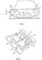
- an armored earth-moving machine generally comprises a chassis 1, and two undercarriages 2, arranged symmetrically with respect to the plane of symmetry of the chassis.
- Each train comprises a track 10 constituted by articulated pads 12 and which is mounted around a sprocket 20, a tensioner roller 40 and three support rollers 30,31 and 32.
- each shoe of the track is rectangular in shape and has a central tooth 14 and two rectangular notches 16,17 arranged on either side of the plane of symmetry of the tooth.
- Two consecutive pads 12 1 , 12 2 are free to rotate about a common axis 15.
- the tensioner roller 40 of a machine comprises a bore, not shown, intended to receive the axis around which said tensioner freely rotates, a rim 43, a groove 42 separating said rim in two parts 43 1 and 43 2 bordered by flanges respectively 44 1 and 44 2 and partially covered by a tread, respectively 45 1 and 45 2 made of elastomer, deposited for example by vulcanization.
- the supporting rollers are similar to the tensioning roller.
- the sprocket 20 has two sets of teeth 21 which mesh in the notches 16,17 of the track 10.
- the axis of the tensioning roller 40 is moved in the direction of the gypsy 20 then the track 10 is positioned around the rollers 30, 31, 32 and 40, then moved in the opposite direction and fixed so as to give some track tension value.
- the groove 42 of the tensioner roller as well as that of each of the carrier rollers allow the passage of the teeth 14 while the contact between the roller and the tracks of the track is carried out by the respective treads of said rollers.
- the flanges 44 associated with the groove serve to guide the teeth 14 of the track 10 and to prevent wear of the rim.
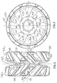
- Figures 4 to 6 show diagrams of a tensioner roller 140 according to the invention. It has a bore 141 intended to receive the axis around which it rotates freely, a rim 143, circular groove 142 separating the rim into two parts 143 1 and 143 2 , each of them having regularly spaced and extending grooves 146 , for each part, over its entire width, from the circular groove 142 to the lateral face 147 of the roller which corresponds to it.
- pads 150 are arranged on each of the elements 148 of each of the parts 143 1 and 143 2 , elements 148 delimited by two grooves 146 consecutive, the circular groove 142 and through one of the lateral surfaces 147 of the roller.
- the peripheral surface of the roller thus constitutes a tread discontinuous.
- pads 150 have an upper elastomer part 151 in direct contact with the track and a 152 steel sole, the internal face has an imprint whose dimensions correspond to those of the surface peripheral elements 148.
- each rim has eight grooves 146 which have substantially the shape of a Vee truncated at the base and the plane P1 of symmetry of the grooves 146 is inclined relative to the diametrical plane P2 of the roller 140.
- This inclination is d '' approximately ⁇ / 4 radians for one of the parts 143 1 and 143 2 , and 3 ⁇ / 4 radians for the other.
- grooves 146 are of the same dimensions and, for the same part, parallel to each other. Their number must be such that the pitch d separating two consecutive grooves 146 must be different from the pitch d1 separating two consecutive teeth 14 from the track 10. In addition, their number must not be excessive, in order to minimize the cost of production and do not risk weakening the roller.
- the grooves 146 of one of the parts 143 1 and 143 2 are offset from those of the other rim by the value of half a groove pitch (d / 2), and this in order to have, in a continuous manner, a lateral surface for guiding the teeth of the track.
- the lateral surface of the sole giving onto the groove 142 is prominent with respect to the rim and serves as a guide for the teeth of the track and as a wear element.
- teeth 21 of the gypsy 20 are placed in notches 16,17 of the track 10 and the latter is centered on the rollers 30, 31, 32 and 140 so that its teeth 14 are in the groove 142 of these last.
- a pre-set value of the track operating voltage 10 is provided by the tensioner roller 140, as above Explain.
- the arrow shown in Figure 4 represents the direction of rotation of the roller tensioner 140 when the machine advances. When this machine does earthwork in a ground where the earth is sticky, the latter tends to stick to the strip rolling constituted by the pads and to be compressed by the pressure that exerts on she tracks it.
- the earth can also be removed well laterally than longitudinally a discharge surface being present on each side of the skids 150.
- the implementation of the invention has shown that a machine whose trains of bearing used a tensioner roller according to the invention had reliability significantly increased compared to a machine according to the state of the art.
- rollers according to the invention can be produced from numerous materials such as for example metals, alloys or composites and can, depending on the nature of this material, be produced by different methods such as machining, molding, forging, mechanical welding ... It is obvious that many modifications can be made to the variant embodiment described above, without departing from the scope of the invention.
- the carrier rollers can also be produced according to the invention.
- the continuity of the peripheral surface can be, partly preserved, by keeping a bead of material, the grooves opening out only partially in the lateral surface of the roller.
- the roller may not have elastomer pads.
- the grooves 146 of one of the parts 143 1 and 143 2 making an angle ⁇ with the diametrical plane P2 of the roller, ⁇ being different from ⁇ / 2 radians, the grooves of the other part can make an angle any with the diametral plane P2 of the roller, this angle being however different from ⁇ / 2 radians.
- a tension roller according to the invention is completely compatible with an automatic track tension control device, playing in this combination, also fully its role.
- the depth of a groove 146 can either be uniform over its entire length or vary, the most important depth being, preferably, on the side of the lateral surface 147 of the roller in which this groove opens.
- lateral surface is meant any external surface of the roller other than the peripheral surface.
Description
La présente invention concerne notamment le domaine des véhicules à chenilles comportant des moyens pour supprimer les matières étrangères qui se déposent autour des galets et des poulies et a plus particulièrement pour objet un galet du type comportant un axe, deux surfaces latérales et une surface périphérique et associé à un chemin de roulement et apte à supprimer ces matières étrangères.The present invention relates in particular to the field of tracked vehicles having means for removing foreign matter which is deposited around rollers and pulleys and more particularly relates to a roller of the type comprising a axis, two lateral surfaces and a peripheral surface and associated with a path rolling and able to remove these foreign materials.
On connait à ce titre le brevet EP-A-0 512 467 qui décrit un engin à chenille, comportant deux trains de roulement chacun comportant principalement une chenille entraínée par un galet moteur, habituellement appelé barbotin et un galet tendeur. Le galet moteur est du type comportant un axe, deux surfaces latérales et une surface périphérique et associé à un chemin de roulement, la surface périphérique présentant en outre une gorge périphérique longitudinale, chacune des surfaces latérales et la gorge périphérique longitudinale délimitant une partie, chacune des surfaces périphériques de ces parties faisant partie de la surface périphérique du galet et comportant des éléments assurant une discontinuité de contact entre le galet et le chemin de roulement, ces éléments étant constitués par des ouvertures axiales et étant aptes à permettre, sous effet de la pression de la chenille, l'évacuation axiales de la boue située entre la chenille et les surfaces périphériques des parties. Cependant lorsque ce type d'engin fonctionne dans des terrains gras, boueux ou caillouteux, la présence de boue ou de cailloux dans la gorge périphérique longitudinale peut entraíner le déchenillage, la rupture du système de tension de la chenille, voire de la chenille elle-même,As such, patent EP-A-0 512 467 is known which describes a tracked vehicle, comprising two undercarriages each comprising mainly a track driven by a drive roller, usually called gypsy and a tensioner roller. The stone motor is of the type comprising an axis, two lateral surfaces and a peripheral surface and associated with a raceway, the peripheral surface further having a longitudinal peripheral groove, each of the lateral surfaces and the peripheral groove longitudinal delimiting a part, each of the peripheral surfaces of these parts forming part of the peripheral surface of the roller and comprising elements ensuring discontinuity of contact between the roller and the raceway, these elements being constituted by axial openings and being able to allow, under the effect of pressure of the track, the axial evacuation of the mud located between the track and the surfaces peripherals of the parties. However when this type of machine works in terrains greasy, muddy or stony, the presence of mud or stones in the peripheral throat longitudinal can cause the tearing, the rupture of the track tension system, even the caterpillar itself,
Deux types de protection contre ces incidents sont actuellement utilisés.Two types of protection against these incidents are currently used.
Le premier, décrit par exemple dans le brevet US4819999, consiste à placer des joints d'étanchéité de façon à éviter l'intrusion de matières étrangères entre la chenille et les galets.The first, described for example in patent US4819999, consists in placing seals in order to avoid the intrusion of foreign matter between the track and the pebbles.
Le deuxième, décrit par exemple dans le brevet US 5330260 consiste à disposer des lames à proximité de la bande de roulement des galets afin d'enlever les matières étrangères, telle la terre, qui peuvent s'y accumuler et créer des surtensions dans la chenille.The second, described for example in US patent 5,330,260, consists in having blades near the roller tread to remove material such as earth, which can accumulate there and create overvoltages in the caterpillar.
Cependant, ces moyens de protection sont fragiles, et leur défaillance en fonctionnement n'est généralement pas décelable.However, these means of protection are fragile, and their failure in generally not detectable.
Lorsque ledit galet tendeur est mobile et la tension contrôlée par un dispositif approprié, tel le dispositif décrit dans le brevet FR2703971, les deux types de protection précédemment cités peuvent être utilisés. En l'absence de ces protections, le pilote est généralement informé lorsque le déplacement du galet tendeur atteint une certaine valeur seuil, ce déplacement pouvant compenser l'apparition d'une certaine épaisseur de matelas de terre sur les galets. Le pilote doit alors dégager ces matelas de terre avant de repartir.When said tensioner roller is mobile and the tension controlled by a device suitable, such as the device described in patent FR2703971, the two types of protection previously cited can be used. In the absence of these protections, the pilot is generally informed when the displacement of the tensioner roller reaches a certain value threshold, this displacement being able to compensate for the appearance of a certain thickness of mattress of earth on the pebbles. The pilot must then clear these earth mattresses before leaving.
Un tel dispositif nécessite donc des temps d'immobilisation importants ainsi que des moyens de contrôle coûteux. Such a device therefore requires significant downtime as well than costly means of control.
Le but de l'invention est de palier ces inconvénients en proposant des moyens simples et résistants permettant de supprimer, pendant le fonctionnement de l'engin, les matières étrangères qui se déposent autour des galets.The object of the invention is to overcome these drawbacks by proposing simple and resistant means to remove, during operation of the machine, the foreign materials which deposit around the rollers.
La solution apportée est un élément tournant, tel une poulie ou un galet du type comportant un axe, deux surfaces latérales et une surface périphérique, associé à un chemin de roulement, caractérisé en ce que la surface périphérique du galet comporte au moins une gorge débouchant dans au moins l'une des surfaces latérales du galet et assurant une discontinuité de contact entre le galet et le chemin de roulement.The solution provided is a rotating element, such as a pulley or a roller of the type comprising an axis, two lateral surfaces and a peripheral surface, associated with a raceway, characterized in that the peripheral surface of the roller has at least one groove opening into at least one of the surfaces side of the roller and ensuring discontinuity of contact between the roller and the track of rolling.
Selon une caractéristique permettant d'accroítre l'élimination desdites matières étrangères, au moins une des surfaces latérales du galet est concave.According to a characteristic allowing to increase the elimination of said foreign matter, at least one of the side surfaces of the roller is concave.
Dans le but d'accroítre la résistance du galet, des cordons réalisés dans le même matériau que celui du galet, peuvent être prévus de façon à relier, au niveau de la surface latérale du galet, les sommets d'une même gorge, les gorges ne débouchant plus alors que partiellement dans la surface latérale du galet.In order to increase the resistance of the roller, cords made in the same material as that of the roller, can be provided so as to connect, at the level of the lateral surface of the roller, the summits of the same groove, the grooves do not opening more then only partially into the lateral surface of the roller.
Selon un mode de réalisation particulier, les gorges sont de mêmes dimensions et chaque gorge présente un plan de symétrie, ce plan de symétrie faisant un angle α radians avec le plan diamétral du galet, α étant différent de π/2 radians.According to a particular embodiment, the grooves are the same dimensions and each groove has a plane of symmetry, this plane of symmetry making an angle α radians with the diametrical plane of the roller, α being different from π / 2 radians.
Selon une caractéristique particulière, la surface périphérique du galet présente en outre une gorge périphérique longitudinale délimitant deux parties.According to a particular characteristic, the peripheral surface of the roller also has a longitudinal peripheral groove defining two parts.
Selon une caractéristique additionnelle, les gorges sont régulièrement espacées, avec un pas d entre elles sur les deux parties, mais décalées d'un demi pas d'une partie à l'autre.According to an additional characteristic, the grooves are regularly spaced, with a step between them on the two parts, but offset by a half not from one party to another.
Selon une autre caractéristique additionnelle, les gorges de l'une des parties faisant un angle α avec le plan diamétral du galet, α étant différent de π/2 radians et les gorges de l'autre partie font un angle de (π-α) radians.According to another additional characteristic, the grooves of one of the parts making an angle α with the diametral plane of the roller, α being different from π / 2 radians and the grooves of the other part make an angle of (π-α) radians.
Dans le but de limiter le bruit et l'usure du galet, celui-ci peut comporter un revêtement, du type patin, en élastomère.In order to limit the noise and wear of the roller, it may include a pad type coating, elastomer.
Selon une autre caractéristique, un galet selon l'invention est appliqué à un train de roulement du type comportant une chenille et des galets.According to another characteristic, a roller according to the invention is applied to a undercarriage of the type comprising a track and rollers.
Dans le cas, où la chenille possède des dents qui sont espacées avec un pas d1 et où les gorges du galet sont espacées avec un pas d, il est préférable que d et d1 soient différents afin de réduire les risques de déchenillage. In the case where the caterpillar has teeth which are spaced apart with a pitch d1 and where the grooves of the roller are spaced with a pitch d, it is preferable that d and d1 are different in order to reduce the risk of weeding.
D'autres avantages et caractéristiques de la présente invention apparaítront dans la description d'un mode de réalisation de l'invention appliqué à un engin blindé de terrassement, en regard des figures annexées parmi lesquelles :
- la figure 1 présente un schéma général d'un engin blindé de terrassement,
- la figure 2 montre un schéma des patins d'une chenille,
- sur la figure 3, est représenté un galet selon l'état de la technique,
- les figures 4, 5 et 6 montrent des schémas d'un galet tendeur selon ladite variante de réalisation de l'invention.
- FIG. 1 presents a general diagram of an armored earth-moving machine,
- FIG. 2 shows a diagram of the tracks of a caterpillar,
- FIG. 3 shows a roller according to the state of the art,
- Figures 4, 5 and 6 show diagrams of a tensioner roller according to said alternative embodiment of the invention.
Comme montré sur la figure 1, un engin blindé de terrassement, appelé engin
dans la suite, comporte généralement un châssis 1, et deux trains de roulement 2,
disposés de façon symétrique par rapport au plan de symétrie du châssis. Chaque
train comporte une chenille 10 constituée par des patins articulés 12 et qui est
montée autour d'un barbotin 20, d'un galet tendeur 40 et trois galets porteurs 30,31
et 32.As shown in Figure 1, an armored earth-moving machine, called a machine
in the following, generally comprises a chassis 1, and two
Comme montré sur la figure 2, chaque patin de la chenille est de forme
rectangulaire et comporte une dent centrale 14 et deux échancrures rectangulaires
16,17 disposées de part et d'autre du plan de symétrie de la dent. Deux patins
consécutifs 121, 122 sont libres en rotation autour d'un axe commun 15.As shown in Figure 2, each shoe of the track is rectangular in shape and has a central tooth 14 and two
Comme montré sur la figure 3, le galet tendeur 40 d'un engin selon l'état de la
technique comporte un alésage, non représenté, destiné à recevoir l'axe autour
duquel tourne librement ledit tendeur, une jante 43, une gorge 42 séparant ladite
jante en deux parties 431 et 432 bordées par des flasques respectivement 441 et
442 et recouvertes partiellement par une bande de roulement, respectivement 451 et
452 en élastomère, déposée par exemple par vulcanisation.As shown in FIG. 3, the
Les galets porteurs sont similaires au galet tendeur.The supporting rollers are similar to the tensioning roller.
Le barbotin 20 comporte deux séries de dents 21 qui s'engrènent dans les
échancrures 16,17 de la chenille 10.The
Avant le fonctionnement de l'engin, l'axe du galet tendeur 40 est déplacé dans
la direction du barbotin 20 puis la chenille 10 est positionnée autour des galets 30,
31, 32 et 40, puis déplacé en sens inverse et fixé de façon à donner une certaine
valeur de tension à la chenille.Before the operation of the machine, the axis of the
La gorge 42 du galet tendeur ainsi que celle de chacun des galets porteurs
permettent le passage des dents 14 tandis que le contact galet - patins de la chenille
s'effectue par les bandes de roulement respectives desdits galets. Les flasques 44
associés à la gorge servent à guider les dents 14 de la chenille 10 et à éviter l'usure
de la jante. The
Les figures 4 à 6 présentent des schémas d'un galet tendeur 140 selon
l'invention. Il comporte un alésage 141 destiné à recevoir l'axe autour duquel il
tourne librement, une jante 143, gorge circulaire 142 séparant la jante en deux
parties 1431 et 1432, chacune d'elles possédant des gorges 146 régulièrement
espacées et s'étendant, pour chaque partie, sur toute sa largeur, depuis la gorge
circulaire 142 jusqu'à la face latérale 147 du galet qui lui correspond.Figures 4 to 6 show diagrams of a
Afin de limiter l'usure qui résulterait d'un contact métal-métal entre les jantes
et la chenille 10, des patins 150 sont disposés sur chacun des élements 148 de
chacune des parties 1431 et 1432, éléments 148 délimités par deux gorges 146
consécutives, la gorge circulaire 142 et par l'une des surfaces latérales 147 du
galet.In order to limit the wear which would result from a metal-metal contact between the rims and the track 10,
La surface périphérique du galet constitue ainsi une bande de roulement discontinue.The peripheral surface of the roller thus constitutes a tread discontinuous.
Ces patins 150 comportent une partie supérieure en élastomère 151 en
contact direct avec la chenille et une semelle 152 en acier dont la face interne
possède une empreinte dont les dimensions correspondent à celles de la surface
périphérique des éléments 148.These
Ces patins 150 sont fixés sur les jantes par des vis 153.These
Dans cette variante de réalisation, chaque jante comporte huit gorges 146
qui ont sensiblement la forme d'un Vé tronqué à la base et le plan P1 de symétrie
des gorges 146 est incliné par rapport au plan diamétral P2 du galet 140. Cette
inclinaison est d'environ π/4 radians pour l'une des parties 1431 et 1432, et 3π/4
radians pour l'autre.In this variant embodiment, each rim has eight
Ces gorges 146 sont de mêmes dimensions et, pour une même partie,
parallèles entre elles. Leur nombre doit être tel que le pas d séparant deux gorges
146 consécutives doit être différent du pas d1 séparant deux dents 14 consécutives
de la chenille 10. En outre, leur nombre ne doit pas être excessif, afin de minimiser
le coût de production et de ne pas risquer de fragiliser le galet. Enfin, comme montré
sur les figures 4 et 5, les gorges 146 de l'une des parties 1431 et 1432 sont
décalées de celles de l'autre jante de la valeur d'un demi pas de gorge (d/2), et ceci
afin d'avoir, d'une manière continue, une surface latérale de guidage des dents de
la chenille. En outre la surface latérale de la semelle donnant sur la gorge 142 est
proéminente par rapport à la jante et sert de guidage des dents de la chenille et
d'élément d'usure.These
Enfin, les deux surfaces latérales 147 du galet sont concaves, la périphérie
apparaissant donc en saillie.Finally, the two
En fonctionnement, des dents 21 du barbotin 20 sont placées dans des
échancrures 16,17 de la chenille 10 et cette dernière est centrée sur les galets 30,
31, 32 et 140 de telle sorte que ses dents 14 soient dans la gorge 142 de ces
derniers. Une valeur fixée au préalable de tension de fonctionnement de la chenille
10 est assurée par l'intermédiaire du galet tendeur 140, comme précédemment
expliqué. La flèche montrée sur la figure 4 représente le sens de rotation du galet
tendeur 140 lorsque l'engin avance. Lorsque cet engin fait du terrassement dans un
terrain où la terre est collante, cette dernière a tendance à se coller sur la bande
roulante constituée par les patins et à être comprimée par la pression qu'exerce sur
elle la chenille.In operation,
Avec un galet selon l'état de la technique, la terre ne peut être évacuée, sous l'effet de ladite pression, que latéralement par une surface très réduite correspondante à une couronne de diamètre intérieure égale à celle du galet et d'épaisseur égale à celle du matelas de terre. Aussi, cette surface d'évacuation est insuffisante et provoque l'apparition de matelas épais de terre conduisant aux incidents précités.With a roller according to the state of the art, the earth cannot be evacuated, under the effect of said pressure, only laterally by a very reduced surface corresponding to a crown with an internal diameter equal to that of the roller and of thickness equal to that of the earth mattress. Also, this discharge surface is insufficient and causes the appearance of thick earth mattresses leading to aforementioned incidents.
Avec un galet de tension selon l'invention, la terre peut être évacuée aussi
bien latéralement que longitudinalement une surface d'évacuation étant présente sur
chacun des cotés des patins 150.With a tension roller according to the invention, the earth can also be removed
well laterally than longitudinally a discharge surface being present on
each side of the
En outre, toute la terre présente dans la gorge 142 et dans les gorges 146 a
aussi tendance, sous l'effet de la pression à être évacuée vers l'extérieur du galet, la
section latérale des gorges 146 étant très importante.In addition, all the soil present in the
La mise en oeuvre de l'invention a montré qu'un engin dont les trains de roulement utilisaient un galet tendeur selon l'invention présentait une fiabilité nettement accrue par rapport à un engin selon l'état de la technique.The implementation of the invention has shown that a machine whose trains of bearing used a tensioner roller according to the invention had reliability significantly increased compared to a machine according to the state of the art.
Les galets selon l'invention peuvent être réalisées dans de nombreuses
matières telles par exemple des métaux, des alliages ou des composites et être,
suivant la nature de cette matière, réalisés par différentes méthodes telles l'usinage,
le moulage, le forgeage, le mécano-soudage...
Il est évident que de nombreuses modifications peuvent être apportées à la variante
de réalisation précédemment décrite, sans sortir du champs de l'invention. Ainsi, les
galets porteurs peuvent aussi être réalisés selon l'invention. De plus, la continuité de
la surface périphérique peut être, en partie préservée, en conservant un cordon de
matière, les gorges ne débouchant alors que partiellement dans la surface latérale
du galet.The rollers according to the invention can be produced from numerous materials such as for example metals, alloys or composites and can, depending on the nature of this material, be produced by different methods such as machining, molding, forging, mechanical welding ...
It is obvious that many modifications can be made to the variant embodiment described above, without departing from the scope of the invention. Thus, the carrier rollers can also be produced according to the invention. In addition, the continuity of the peripheral surface can be, partly preserved, by keeping a bead of material, the grooves opening out only partially in the lateral surface of the roller.
Dans le cas où la chenille comporte elle-même un revêtement en élastomère, le galet peut ne pas comporter de patins en élastomère.If the track itself has an elastomer coating, the roller may not have elastomer pads.
En outre, les gorges 146 de l'une des parties 1431 et 1432, faisant un angle
α avec le plan diamétral P2 du galet, α étant différent de π/2 radians, les gorges de
l'autre partie peuvent faire un angle quelconque avec le plan diamétral P2 du galet,
cet angle étant toutefois différent de π/2 radians.In addition, the
De surcroít un galet tendeur selon l'invention est tout à fait compatible avec un dispositif de contrôle automatique de la tension de la chenille, jouant, dans cette combinaison, aussi pleinement son rôle.In addition a tension roller according to the invention is completely compatible with an automatic track tension control device, playing in this combination, also fully its role.
De plus, la profondeur d'une gorge 146 peut, soit être uniforme sur toute sa
longueur, soit varier, la profondeur la plus importante étant, préférablement, du coté
de la surface latérale 147 du galet dans laquelle débouche cette gorge.In addition, the depth of a
Enfin, par surface latérale, il faut entendre toute surface externe du galet autre que la surface périphérique.Finally, by lateral surface is meant any external surface of the roller other than the peripheral surface.
Claims (9)
- A roller of the type comprising an axle, two side surfaces ( 147 ) and a peripheral surface, combined with a runway ( 10 ), the peripheral surface being in addition provided with a longitudinal peripheral groove ( 142 ), each side surface ( 147 ) and the longitudinal peripheral groove ( 142 ) delimiting a section ( 1431 and 1432 ), each peripheral surface of these parts ( 1431 and 1432 ), belonging to the peripheral surface of the roller and comprising at least one element ( 146 ) which ensures a discontinuous contact between the roller and the runway ( 10 ) , characterised in that the element ( 146 ) consists in a groove one extremity of which opens into the longitudinal peripheral groove ( 142 ) and the other extremity into the side surface of the part ( 1431 and 1432 ) comprising this groove.
- A roller according to claim 1, characterised in that grooves (146 ) open only partly in the roller side surface ( 147 ).
- A roller according to any of the previous claims characterised in that at least one of its side surfaces ( 147 ) is concave.
- A roller according to any of the previous claims, characterised in that each part ( 1431 and 1432 ), comprises several grooves ( 146 ) irregularly spaced.
- A roller according to any of claims 1 to 2, characterised in that grooves ( 146 ) are regularly spaced on both parts ( 1431 and 1432 ), with a pitch d but shifted by a half-pitch.
- A roller according to claim 5, characterised in that grooves ( 146 ) have a plane of symmetry P1 and in that the plane of symmetry forms an angle of α radians with the diametrical plane P2 of the roller, α being different from PI/2 radians.
- A roller according to claim 5, characterised in that grooves (146 ) of one part ( 1431 or 1432 ), form an angle α with the diametrical plane P2 of the roller, α being different from PI/2 radians and the grooves ( 146 ) of the other part form an angle of (PI-α) radians.
- A roller according to any of the previous claims, characterised in that the elements delimited by the said grooves ( 146 ) and the side surface(s) ( 147 ) of the roller, are coated with elastomer skids ( 150 ).
- A track of the type comprising a crawler ( 10 ) and rollers, and using at least one roller according to any of the previous claims.
Applications Claiming Priority (2)
| Application Number | Priority Date | Filing Date | Title |
|---|---|---|---|
| FR9501317 | 1995-02-01 | ||
| FR9501317A FR2729914A1 (en) | 1995-02-01 | 1995-02-01 | GALET WITH DISCONTINUOUS CONTACT |
Publications (2)
| Publication Number | Publication Date |
|---|---|
| EP0725002A1 EP0725002A1 (en) | 1996-08-07 |
| EP0725002B1 true EP0725002B1 (en) | 1998-06-03 |
Family
ID=9475852
Family Applications (1)
| Application Number | Title | Priority Date | Filing Date |
|---|---|---|---|
| EP19960400222 Expired - Lifetime EP0725002B1 (en) | 1995-02-01 | 1996-02-01 | Roller with contact surface discontinuity |
Country Status (4)
| Country | Link |
|---|---|
| EP (1) | EP0725002B1 (en) |
| DE (1) | DE69600325T2 (en) |
| ES (1) | ES2119550T3 (en) |
| FR (1) | FR2729914A1 (en) |
Families Citing this family (4)
| Publication number | Priority date | Publication date | Assignee | Title |
|---|---|---|---|---|
| GB2311971B (en) * | 1996-04-09 | 2000-01-12 | Caterpillar Inc | Metal drive wheel for endless ground engaging drive belts |
| CN108945127B (en) * | 2017-02-06 | 2021-03-26 | 温州泓呈祥科技有限公司 | Driving wheel based on side guide plate |
| US11919584B2 (en) | 2020-01-28 | 2024-03-05 | Caterpillar Inc. | Flip-flop track rollers |
| CN113734309B (en) * | 2021-09-26 | 2024-02-09 | 北京凌天智能装备集团股份有限公司 | Track system and track processing technology |
Family Cites Families (6)
| Publication number | Priority date | Publication date | Assignee | Title |
|---|---|---|---|---|
| FR504534A (en) * | 1919-10-03 | 1920-07-07 | Automobiles & Cycles Peugeot Sa | Tractor Track Improvements |
| US1549594A (en) * | 1922-01-23 | 1925-08-11 | Koehring Co | Tumbler |
| FR1394353A (en) * | 1964-03-27 | 1965-04-02 | Wheel especially for tracked vehicles | |
| US3443844A (en) * | 1967-08-15 | 1969-05-13 | Katrak Vehicle Co | Self-cleaning track and drive assembly for track-laying vehicles |
| US3472563A (en) * | 1967-11-22 | 1969-10-14 | Outboard Marine Corp | Vehicle track |
| CA2062549C (en) * | 1991-05-07 | 1995-11-07 | Robert Willis Brittain | Drive wheel for a belted track crawler |
-
1995
- 1995-02-01 FR FR9501317A patent/FR2729914A1/en active Granted
-
1996
- 1996-02-01 EP EP19960400222 patent/EP0725002B1/en not_active Expired - Lifetime
- 1996-02-01 DE DE1996600325 patent/DE69600325T2/en not_active Expired - Fee Related
- 1996-02-01 ES ES96400222T patent/ES2119550T3/en not_active Expired - Lifetime
Also Published As
| Publication number | Publication date |
|---|---|
| FR2729914A1 (en) | 1996-08-02 |
| FR2729914B1 (en) | 1997-02-28 |
| DE69600325T2 (en) | 1998-12-24 |
| EP0725002A1 (en) | 1996-08-07 |
| DE69600325D1 (en) | 1998-07-09 |
| ES2119550T3 (en) | 1998-10-01 |
Similar Documents
| Publication | Publication Date | Title |
|---|---|---|
| US20040017109A1 (en) | Split wheel and method for installing endless track | |
| FR2491836A1 (en) | RIM AND TIRE ADAPTER ASSEMBLY | |
| FR2578200A1 (en) | MULTI-PART TRUCK FOR TRUCK OR BUS TIRES | |
| FR2703970A1 (en) | Subframe structure for vehicle on raceways, and vehicle equipped with such a structure. | |
| EP0725002B1 (en) | Roller with contact surface discontinuity | |
| FR2521942A1 (en) | CRAMPS OF CHAIN OF TRACKED VEHICLES | |
| FR2718701A3 (en) | Tracking mechanism assembly, particularly for small excavators. | |
| EP1044870B1 (en) | Improved drive wheel for rubber crawler | |
| FR2845344A1 (en) | ENDLESS FLEXIBLE BELT TRACK WITH REINFORCEMENT PATCHES, ESPECIALLY FOR ALL-TERRAIN VEHICLES | |
| CA2540813C (en) | System for guiding a vehicle along at least one guiding rail | |
| FR2711959A1 (en) | Caterpillar track drive device for all-terrain vehicles | |
| FR2753679A1 (en) | Scraper for vehicle endless track | |
| CA2431569C (en) | Flexible track motor vehicle drive system and the resulting motor vehicle | |
| FR2704035A1 (en) | Assembly of a friction element equipped with a disc brake spring. | |
| FR2765150A1 (en) | RIM FOR BICYCLE WHEEL | |
| FR2473424A1 (en) | ANTI-SLIP DEVICE FOR A MOTOR VEHICLE | |
| FR2633679A1 (en) | Rolling-contact bearing including at least one split race and an assembly linkage | |
| EP0326774B1 (en) | Disc brake and brake pad therefor | |
| FR2473456A1 (en) | GROUND CONTACT MEMBER FOR CONTINUOUS TRACK VEHICLES | |
| EP1152941A1 (en) | Device for lifting a caterpillar road wheel | |
| CA2395757C (en) | Split wheel and method for installing endless track | |
| EP0696976B1 (en) | Track for vehicle comprising a flexible material band | |
| FR2802887A1 (en) | FLEXIBLE TRACK DRIVE DEVICE FOR MOTOR VEHICLE | |
| FR2526849A1 (en) | Drill bit for boring oil wells, mines, etc. - having rolling cutters with sealed lining comprising rigid ring and elastomeric sealing ring | |
| FR3136196A1 (en) | Track widener for inflating/deflating vehicle tires |
Legal Events
| Date | Code | Title | Description |
|---|---|---|---|
| PUAI | Public reference made under article 153(3) epc to a published international application that has entered the european phase |
Free format text: ORIGINAL CODE: 0009012 |
|
| 17P | Request for examination filed |
Effective date: 19960216 |
|
| AK | Designated contracting states |
Kind code of ref document: A1 Designated state(s): CH DE ES GB LI SE |
|
| 17Q | First examination report despatched |
Effective date: 19961126 |
|
| GRAG | Despatch of communication of intention to grant |
Free format text: ORIGINAL CODE: EPIDOS AGRA |
|
| GRAG | Despatch of communication of intention to grant |
Free format text: ORIGINAL CODE: EPIDOS AGRA |
|
| GRAH | Despatch of communication of intention to grant a patent |
Free format text: ORIGINAL CODE: EPIDOS IGRA |
|
| GRAH | Despatch of communication of intention to grant a patent |
Free format text: ORIGINAL CODE: EPIDOS IGRA |
|
| GRAA | (expected) grant |
Free format text: ORIGINAL CODE: 0009210 |
|
| AK | Designated contracting states |
Kind code of ref document: B1 Designated state(s): CH DE ES GB LI SE |
|
| REG | Reference to a national code |
Ref country code: CH Ref legal event code: EP |
|
| REF | Corresponds to: |
Ref document number: 69600325 Country of ref document: DE Date of ref document: 19980709 |
|
| GBT | Gb: translation of ep patent filed (gb section 77(6)(a)/1977) |
Effective date: 19980716 |
|
| REG | Reference to a national code |
Ref country code: CH Ref legal event code: NV Representative=s name: A. MISRACHI |
|
| REG | Reference to a national code |
Ref country code: ES Ref legal event code: FG2A Ref document number: 2119550 Country of ref document: ES Kind code of ref document: T3 |
|
| PLBE | No opposition filed within time limit |
Free format text: ORIGINAL CODE: 0009261 |
|
| STAA | Information on the status of an ep patent application or granted ep patent |
Free format text: STATUS: NO OPPOSITION FILED WITHIN TIME LIMIT |
|
| 26N | No opposition filed | ||
| REG | Reference to a national code |
Ref country code: GB Ref legal event code: IF02 |
|
| PGFP | Annual fee paid to national office [announced via postgrant information from national office to epo] |
Ref country code: GB Payment date: 20020122 Year of fee payment: 7 |
|
| PGFP | Annual fee paid to national office [announced via postgrant information from national office to epo] |
Ref country code: SE Payment date: 20020214 Year of fee payment: 7 |
|
| PGFP | Annual fee paid to national office [announced via postgrant information from national office to epo] |
Ref country code: DE Payment date: 20020426 Year of fee payment: 7 |
|
| PG25 | Lapsed in a contracting state [announced via postgrant information from national office to epo] |
Ref country code: GB Free format text: LAPSE BECAUSE OF NON-PAYMENT OF DUE FEES Effective date: 20030201 |
|
| PG25 | Lapsed in a contracting state [announced via postgrant information from national office to epo] |
Ref country code: SE Free format text: LAPSE BECAUSE OF NON-PAYMENT OF DUE FEES Effective date: 20030202 |
|
| PGFP | Annual fee paid to national office [announced via postgrant information from national office to epo] |
Ref country code: ES Payment date: 20030213 Year of fee payment: 8 |
|
| PGFP | Annual fee paid to national office [announced via postgrant information from national office to epo] |
Ref country code: CH Payment date: 20030228 Year of fee payment: 8 |
|
| PG25 | Lapsed in a contracting state [announced via postgrant information from national office to epo] |
Ref country code: DE Free format text: LAPSE BECAUSE OF NON-PAYMENT OF DUE FEES Effective date: 20030902 |
|
| GBPC | Gb: european patent ceased through non-payment of renewal fee | ||
| EUG | Se: european patent has lapsed | ||
| PG25 | Lapsed in a contracting state [announced via postgrant information from national office to epo] |
Ref country code: ES Free format text: LAPSE BECAUSE OF NON-PAYMENT OF DUE FEES Effective date: 20040202 |
|
| PG25 | Lapsed in a contracting state [announced via postgrant information from national office to epo] |
Ref country code: LI Free format text: LAPSE BECAUSE OF NON-PAYMENT OF DUE FEES Effective date: 20040229 Ref country code: CH Free format text: LAPSE BECAUSE OF NON-PAYMENT OF DUE FEES Effective date: 20040229 |
|
| REG | Reference to a national code |
Ref country code: CH Ref legal event code: PL |
|
| REG | Reference to a national code |
Ref country code: ES Ref legal event code: FD2A Effective date: 20040202 |