EP0724963A1 - Drucker mit thermischer Farbstoffübertragung durch Diffusion und Gebrauchsverfahren - Google Patents
Drucker mit thermischer Farbstoffübertragung durch Diffusion und Gebrauchsverfahren Download PDFInfo
- Publication number
- EP0724963A1 EP0724963A1 EP95200236A EP95200236A EP0724963A1 EP 0724963 A1 EP0724963 A1 EP 0724963A1 EP 95200236 A EP95200236 A EP 95200236A EP 95200236 A EP95200236 A EP 95200236A EP 0724963 A1 EP0724963 A1 EP 0724963A1
- Authority
- EP
- European Patent Office
- Prior art keywords
- printer
- dye
- quality
- image
- drive motor
- Prior art date
- Legal status (The legal status is an assumption and is not a legal conclusion. Google has not performed a legal analysis and makes no representation as to the accuracy of the status listed.)
- Withdrawn
Links
Images

Classifications
-
- B—PERFORMING OPERATIONS; TRANSPORTING
- B41—PRINTING; LINING MACHINES; TYPEWRITERS; STAMPS
- B41J—TYPEWRITERS; SELECTIVE PRINTING MECHANISMS, i.e. MECHANISMS PRINTING OTHERWISE THAN FROM A FORME; CORRECTION OF TYPOGRAPHICAL ERRORS
- B41J2/00—Typewriters or selective printing mechanisms characterised by the printing or marking process for which they are designed
- B41J2/315—Typewriters or selective printing mechanisms characterised by the printing or marking process for which they are designed characterised by selective application of heat to a heat sensitive printing or impression-transfer material
- B41J2/32—Typewriters or selective printing mechanisms characterised by the printing or marking process for which they are designed characterised by selective application of heat to a heat sensitive printing or impression-transfer material using thermal heads
- B41J2/325—Typewriters or selective printing mechanisms characterised by the printing or marking process for which they are designed characterised by selective application of heat to a heat sensitive printing or impression-transfer material using thermal heads by selective transfer of ink from ink carrier, e.g. from ink ribbon or sheet
Definitions
- the present invention relates to a thermal dye diffusion printer and to a method of operating such a printer.
- this invention relates to a method of representing an image of the human body obtained during medical imaging and most particularly to a printer intended for printing medical image picture data received from a medical imaging device.
- Thermal dye diffusion printing also known as sublimation printing, uses a dye transfer process in which a carrier containing a dye is disposed between a receiver material, such as a transparent material or paper, in sheet or web form, and a print head formed of a plurality of individual heat producing elements.
- the receiver material is mounted on a rotatable drum.
- the carrier and the receiver material are generally moved relative to the print head which is fixed.
- a particular heating element is energised, it is heated and causes dye to transfer, e.g. by diffusion or sublimation, from the carrier to an image pixel (or picture element") in the receiver material.
- the density of the printed dye is a function of the temperature of the heating element and time the carrier is heated. In other words, the heat delivered from the heating element to the carrier causes dye to transfer to the receiver material to make thereon an image related to the amount of heat.
- Thermal dye transfer printing apparatus offer the advantage of true "continuous tone" dye density transfer. By varying the heat applied by each heating element to the carrier, a variable density image pixel is formed in the receiver material.
- a standard quality operating mode For example, in the premium quality mode one or more of the following changes may be desirable:
- a thermal dye diffusion printer comprising: a print head; control means for receiving image data; drive means for passing a dye carrier and a receiver material adjacent the print head, the drive means including a variable speed drive motor; and heating energy feed means for feeding heating energy to the print head in response to the image data to transfer a dye image to the receiver material, the heating energy and the speed of the drive motor being controlled in accordance with a predetermined print quality, wherein the printer is capable of operating in at least two modes, including a standard quality operating mode in which the drive motor is driven at a relatively high speed and at least one premium quality operating mode in which the drive motor is driven at a relatively slow speed, characterised by automatic change-over means for switching the printer between operating modes.
- a method of operating a thermal dye diffusion printer comprising: passing a dye carrier and a receiver material adjacent a print head, with the dye carrier between the print head and the receiver material, by means of a variable speed drive motor; feeding heating energy to the print head in accordance with image data to transfer a dye image to the receiver material; and controlling the heating energy and the speed of the drive motor in accordance with the predetermined print quality, characterised by automatically switching the printer between at least two operating modes including a standard quality operating mode in which the drive motor is driven at a relatively high speed and a premium quality operating mode in which the drive motor is driven at a relatively slow speed.
- the print head used in the printer according to the invention may take a number of different forms.
- the print head may comprise a thermal print head for image-wise heating the dye carrier, comprising individually energisable juxtaposed heating elements.
- Thermal print heads that can be used to transfer dye from dye carriers to a receiving material sheet are commercially available and include the Fujitsu Head FTP-040 MCS001, the TDK Thermal Head F415 HH7-1089 and the Rohm Thermal Head KE 2008-F3.
- print head examples include those based on laser technology or based on resistive ribbon technology.
- a laser induced dye thermal transfer apparatus is described in European patent specification EP-A-0343443 (Agfa-Gevaert NV).
- a support member of the dye carrier is an electrically resistive ribbon which consists for example of a multi-layered structure of a carbon-loaded polycarbonate coated with a thin aluminium film.
- Current is injected into the resistive ribbon by electrically addressing one of a plurality of print head electrodes, thus resulting in highly localised heating of the ribbon beneath the relevant electrode.
- line-type printing heads having a one dimensional array have been referred to here, the present invention can also make use of two dimensionally arranged printing head arrays.
- the present invention is equally applicable to thermal wax printing.
- the automatic changeover means operates in response to predetermined quality signals included in the image data fed to the printer.
- the method according to this embodiment of the invention thus preferably includes automatically switching between the operating modes in response to these predetermined quality signals.
- the predetermined quality signals may be included in the data fed to the printer in a number of ways, for example (i) within the image data (i.e. part of the "bit-map" and read, for example by optical character recognition or (ii) aside from the image data in a so-called "header". Examples of such data may included the type of medical apparatus involved, the name of the operator or specialist, the name of the patient and the patient's medical history.
- Thermal imaging can be used for production of both transparencies and reflection-type prints.
- recording materials based on an opaque, usually white, base are used, whereas in the medical diagnostic field monochrome, usually black, images on a transparent base find wide application, since such prints can conveniently be viewed by means of a light box.
- the printer may further comprise a sensor for generating a signal indicative of the nature of the dye carrier, wherein the automatic change-over means operates in response to the dye carrier nature signals.
- the method according to this embodiment of the invention thus preferably further comprises automatically switching between the operating modes in response to the dye carrier nature signals.
- this sensor may be capable of distinguishing between a dye carrier carrying monochrome (e.g. black) dye and a dye carrier carrying a plurality of coloured dyes.
- a suitable sensor for this purpose is a high efficiency light emitting diode such as Wustlich type WU-SHR-37C or WU-SY-37C or a photodiode such as Siemens type BPX 90.
- the printer may further comprise a sensor for generating a signal indicative of the type of the receiver material, wherein the automatic change-over means operates in response to the receiver material type signals.
- the method according to this embodiment of the invention thus preferably further comprises automatically switching between the operating modes in response to the receiver material type signals.
- a suitable sensor for this purpose is a so-called slotted optical switch such as Sharp type GP 1A 17.
- the printer may further comprise a sensor for generating a signal indicative of the quality of the printed image, wherein the automatic change-over means operates in response to the printed image quality signals.
- the method according to this embodiment of the invention thus preferably further comprises automatically switching between the operating modes in response to the printed image quality signals.
- the calibration of this control may involve the making and examination of a test print.
- a suitable sensor for this purpose is an opto-electronic sensor with a high dynamic range such as Texas Instruments type TLS 230.
- the image data may be in the form of medical image picture data received from a medical imaging device, especially a scanning medical image camera.
- the image data may include additional data alpha/numeric data, Such additional data alpha/numeric data may, for example, be related to the subject of the medical image picture. Alternatively or additionally, such additional data alpha/numeric data may, for example, be indicative of technical information related to conditions under which the medical image picture was taken. Ultrasound doppler technology provides colour images for which a lower density print may be more appropriate, whereas in computer thermographic imaging and in magnetic resonance imaging generally black and white images of high density are preferred.
- the additional alpha/numeric data included in the image data may relate to these requirements.
- the method according to the invention preferably includes automatically switching between the operating modes in response to predetermined quality signals included in this additional data.
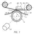
- the printer is capable of printing a line of pixels at a time on a receiver material or acceptor member 11 from dyes transferred from a carrier or dye-donor element 12.
- the receiver material 11 is in the form of a sheet while the carrier 12 is in the form of a web fed from a supply roller 13 onto a take-up roller 14.
- the receiver material 11 is held against a rotatable drum or platen 15, driven by a drive mechanism which includes a variable speed stepper drive motor 18, which advances the drum 15 and the receiver material sheet 11 past a stationary print head 16.
- the print head 16 presses the carrier 12 against the receiver material 11.
- the print head 16 includes a plurality of heating elements 28, for example equal in number to the number of pixels in the image data in a line memory.
- the image-wise heating of the carrier is performed on a line by line basis, with the heating resistors geometrically juxtaposed each along another and with gradual construction of the output density as described, for example, in European Patent Application 91201608.6 (Agfa-Gevaert).
- Each of the resistors is capable of being energised by heating pulses, the energy of which is controlled in accordance with the required density of the corresponding picture element.
- the supply roller 13 and the take-up roller 14 are also driven by the variable speed motor 18 via a slipping coupling mechanism (not shown).
- the supply roll 13 is not driven, but is freely rotatably mounted and is provided with a braking mechanism to maintain a predetermined tension in the web of the carrier 12.
- the printer is capable of operating in at least two modes, including a standard quality operating mode in which the drive motor 18 is driven at a relatively high speed and a premium quality operating mode in which the drive motor 18 is driven at a relatively slow speed.
- a carrier sensor 42 positioned adjacent the carrier material path generates a signal indicative of the nature of the dye carrier 12.
- the sensor 42 is capable of distinguishing between a dye carrier carrying only black dye and a carrier carrying a plurality of coloured dyes.
- a further sensor 43 positioned adjacent the receiver material path, upstream of the print head 16, generates a signal indicative of the type of the receiver material 11.
- a still further sensor 44 positioned adjacent the receiver material path, downstream of the print head 16, generates a signal indicative of the quality of the printed image.
- a digital signal representation is obtained in an image acquisition apparatus 21, for example from an X-ray camera 40.
- the image data includes not only picture data, but also additional alpha/numeric data related to the subject of the X-ray picture and indicative of technical information related to conditions under which the X-ray picture was taken, this additional data being supplied from a keyboard 45 or a remote control device 46.
- the image acquisition apparatus 21 serves to separate out picture data from the alpha/numeric data contained in the image data, such as by optical character recognition (often indicated by "OCR") of the alpha/numeric data.
- OCR optical character recognition
- the picture data signal is applied via a digital interface 22 and a first storage means (MEMORY) 23 to a data processor 24, which assigns a pulse width and number and the heating energy applied to a given heating element 28.
- the digital image signals are fed via a line buffer 33 to a parallel to serial converter 25 of which an advantageous embodiment is disclosed in European Patent Application 91201608.6 (referred to above) to produce a stream of serial data of bits representing the next line of data to be printed which is passed to a second storage means in the form of a shift register 26. Thereafter, under controlled conditions, these data bits are supplied in parallel to the associated inputs of a latch register 27. Once the bits of data from the shift register 26 are stored in the latch register 27, another line of bits can be subsequently clocked into the shift register 26.
- the upper terminals 30 of the heating elements 28 are connected to a positive voltage source V, while the lower terminals 31 of the heating elements are respectively connected to the collectors of drive transistors 29, whose emitters are grounded. These transistors 29 are selectively turned on by a high state signal, indicated as an ANDed STROBE signal supplied on line 32 applied to the bases of the transistors 29 to allow energy to flow through the associated heating elements 28.
- Automatic change-over means 41 mainly comprising a dedicated software program in addition to the above mentioned sensors and user preferences, are provided for switching the printer between the operating modes.
- the change-over means 41 receives signals from the carrier sensor 42, the receiving material sensor 43 and the output sensor 44 indicative of the nature of the dye carrier 12, the nature of the receiving material 11 and the quality of the printed image respectively.
- the change-over means 41 also receives alpha/numeric data separated from the image signal by the image acquisition apparatus 21.
- the change-over means 41 operates in response to predetermined quality signals included in the image data, the dye carrier nature signal from the sensor 42, the receiver material type from the sensor 43 and the printed image quality signals from the sensor 44, to adjust the speed of the variable speed motor 18 and to change the criteria applied by the processing unit 24, in particular to change one or more of pulse width, pulse number and heating energy.
- the heating energy and the speed of the drive motor 18 is thereby controlled in accordance with the predetermined print quality.
- the repetition strobe period (t s ) consists of one heating cycle (t son ) and one cooling cycle (t s - t son ) as indicated in Figure 3.
- the strobe pulse width (t son ) is the time during which an enable strobe signal is on.
- the strobe duty cycle of a heating element is the ratio of the pulse width (t son ) to the repetition strobe period (t s ).
- the line time (t l ) is divided by the number (N) of strobe pulses each with a repetition strobe period t s as indicated in Figure 3.
- N the number of strobe pulses each with a repetition strobe period t s as indicated in Figure 3.
- the maximum diffusion time would be reached after 1024 sequential strobe periods.
Landscapes
- Electronic Switches (AREA)
Priority Applications (2)
| Application Number | Priority Date | Filing Date | Title |
|---|---|---|---|
| EP95200236A EP0724963A1 (de) | 1995-01-31 | 1995-01-31 | Drucker mit thermischer Farbstoffübertragung durch Diffusion und Gebrauchsverfahren |
| JP3116896A JPH08281988A (ja) | 1995-01-31 | 1996-01-26 | 熱色素拡散プリンターとその使用の方法 |
Applications Claiming Priority (1)
| Application Number | Priority Date | Filing Date | Title |
|---|---|---|---|
| EP95200236A EP0724963A1 (de) | 1995-01-31 | 1995-01-31 | Drucker mit thermischer Farbstoffübertragung durch Diffusion und Gebrauchsverfahren |
Publications (1)
| Publication Number | Publication Date |
|---|---|
| EP0724963A1 true EP0724963A1 (de) | 1996-08-07 |
Family
ID=8219984
Family Applications (1)
| Application Number | Title | Priority Date | Filing Date |
|---|---|---|---|
| EP95200236A Withdrawn EP0724963A1 (de) | 1995-01-31 | 1995-01-31 | Drucker mit thermischer Farbstoffübertragung durch Diffusion und Gebrauchsverfahren |
Country Status (2)
| Country | Link |
|---|---|
| EP (1) | EP0724963A1 (de) |
| JP (1) | JPH08281988A (de) |
Citations (5)
| Publication number | Priority date | Publication date | Assignee | Title |
|---|---|---|---|---|
| US4528572A (en) * | 1983-02-08 | 1985-07-09 | Hitachi, Ltd. | Thermal printer |
| US4578689A (en) * | 1984-11-26 | 1986-03-25 | Data Recording Systems, Inc. | Dual mode laser printer |
| US4667208A (en) * | 1984-11-01 | 1987-05-19 | Hitachi, Ltd. | Control system for a color printer |
| EP0257633A1 (de) * | 1986-08-27 | 1988-03-02 | Hitachi, Ltd. | Wärmetransferverfahren und Wärmetransferfarbbogen für die Verwendung in diesem Verfahren |
| EP0517625A2 (de) * | 1991-06-07 | 1992-12-09 | Eastman Kodak Company | Andruckrollensteuerung für einen Drucker |
-
1995
- 1995-01-31 EP EP95200236A patent/EP0724963A1/de not_active Withdrawn
-
1996
- 1996-01-26 JP JP3116896A patent/JPH08281988A/ja active Pending
Patent Citations (5)
| Publication number | Priority date | Publication date | Assignee | Title |
|---|---|---|---|---|
| US4528572A (en) * | 1983-02-08 | 1985-07-09 | Hitachi, Ltd. | Thermal printer |
| US4667208A (en) * | 1984-11-01 | 1987-05-19 | Hitachi, Ltd. | Control system for a color printer |
| US4578689A (en) * | 1984-11-26 | 1986-03-25 | Data Recording Systems, Inc. | Dual mode laser printer |
| EP0257633A1 (de) * | 1986-08-27 | 1988-03-02 | Hitachi, Ltd. | Wärmetransferverfahren und Wärmetransferfarbbogen für die Verwendung in diesem Verfahren |
| EP0517625A2 (de) * | 1991-06-07 | 1992-12-09 | Eastman Kodak Company | Andruckrollensteuerung für einen Drucker |
Also Published As
| Publication number | Publication date |
|---|---|
| JPH08281988A (ja) | 1996-10-29 |
Similar Documents
| Publication | Publication Date | Title |
|---|---|---|
| US5815191A (en) | Direct thermal printing method and apparatus | |
| US4709149A (en) | Copying machine | |
| JPH07503421A (ja) | サーマルプリントヘッドを制御する方法及び装置 | |
| US4795999A (en) | Thermal transfer type printer | |
| EP0654355B1 (de) | Verfahren zur Bilderzeugung durch direkte thermische Aufzeichnung | |
| US5327165A (en) | Electronic printing system for imaging thermally sensitive paper | |
| EP0529530A2 (de) | Verfahren zur Kalibrierung eines Mehrkanal-Druckers | |
| US4517591A (en) | Color printing apparatus | |
| WO1992000195A1 (en) | Parasitic resistance compensation for thermal printers | |
| US5633671A (en) | Recording method and apparatus maintaining constant density by anticipating temperature changes in the recording head | |
| EP0193342B1 (de) | Wärmedrucker | |
| US4899170A (en) | Selective energization of thermal printers | |
| EP0529532A2 (de) | Verfahren und Gerät zur Kalibrierung eines Mehrkanaldruckers | |
| US4623901A (en) | Method and apparatus for printing an image | |
| JPH0639175B2 (ja) | 熱転写式記録装置 | |
| US4814790A (en) | Dual mode thermal printer | |
| EP0724963A1 (de) | Drucker mit thermischer Farbstoffübertragung durch Diffusion und Gebrauchsverfahren | |
| EP0193343B1 (de) | Wärmedrucker | |
| US5382965A (en) | Wax transfer type thermal printing method and thermal printer | |
| JPH071784A (ja) | 熱印刷装置における染料供与体材料の種類の検知 | |
| JP3155468B2 (ja) | ラベルプリンタ | |
| GB2190817A (en) | Thermal image recording apparatus | |
| US5179391A (en) | Thermal printer and thermal printing method | |
| JPS63202473A (ja) | 複数種類の副走査線密度に対応した感熱記録装置 | |
| US5453766A (en) | Method for implementing specific transfer curves in thermal sublimation printers |
Legal Events
| Date | Code | Title | Description |
|---|---|---|---|
| PUAI | Public reference made under article 153(3) epc to a published international application that has entered the european phase |
Free format text: ORIGINAL CODE: 0009012 |
|
| AK | Designated contracting states |
Kind code of ref document: A1 Designated state(s): BE DE FR GB NL |
|
| 17P | Request for examination filed |
Effective date: 19970207 |
|
| GRAG | Despatch of communication of intention to grant |
Free format text: ORIGINAL CODE: EPIDOS AGRA |
|
| STAA | Information on the status of an ep patent application or granted ep patent |
Free format text: STATUS: THE APPLICATION HAS BEEN WITHDRAWN |
|
| 17Q | First examination report despatched |
Effective date: 19980126 |
|
| 18W | Application withdrawn |
Withdrawal date: 19980223 |