EP0723649B1 - Propfen für schrotpatronen zur verminderung des rückstosses - Google Patents
Propfen für schrotpatronen zur verminderung des rückstosses Download PDFInfo
- Publication number
- EP0723649B1 EP0723649B1 EP94928977A EP94928977A EP0723649B1 EP 0723649 B1 EP0723649 B1 EP 0723649B1 EP 94928977 A EP94928977 A EP 94928977A EP 94928977 A EP94928977 A EP 94928977A EP 0723649 B1 EP0723649 B1 EP 0723649B1
- Authority
- EP
- European Patent Office
- Prior art keywords
- round
- charge
- ammunition according
- base
- formations
- Prior art date
- Legal status (The legal status is an assumption and is not a legal conclusion. Google has not performed a legal analysis and makes no representation as to the accuracy of the status listed.)
- Expired - Lifetime
Links
- 239000003638 chemical reducing agent Substances 0.000 title description 2
- 230000015572 biosynthetic process Effects 0.000 claims description 10
- 238000005755 formation reaction Methods 0.000 claims description 10
- 239000000463 material Substances 0.000 claims description 6
- 239000004033 plastic Substances 0.000 claims description 5
- 229920003023 plastic Polymers 0.000 claims description 5
- 238000009827 uniform distribution Methods 0.000 claims description 3
- 238000001746 injection moulding Methods 0.000 claims description 2
- 230000014759 maintenance of location Effects 0.000 claims 3
- 238000002485 combustion reaction Methods 0.000 claims 1
- 238000010304 firing Methods 0.000 description 7
- 230000000717 retained effect Effects 0.000 description 4
- 239000007789 gas Substances 0.000 description 3
- 230000004048 modification Effects 0.000 description 3
- 238000012986 modification Methods 0.000 description 3
- 230000001133 acceleration Effects 0.000 description 2
- 239000004794 expanded polystyrene Substances 0.000 description 2
- 239000004450 Cordite Substances 0.000 description 1
- 206010029216 Nervousness Diseases 0.000 description 1
- 238000010521 absorption reaction Methods 0.000 description 1
- 230000006835 compression Effects 0.000 description 1
- 238000007906 compression Methods 0.000 description 1
- 238000010276 construction Methods 0.000 description 1
- 230000003247 decreasing effect Effects 0.000 description 1
- 238000009826 distribution Methods 0.000 description 1
- 230000000694 effects Effects 0.000 description 1
- 238000004880 explosion Methods 0.000 description 1
- -1 for example Substances 0.000 description 1
- 239000003721 gunpowder Substances 0.000 description 1
- 238000002347 injection Methods 0.000 description 1
- 239000007924 injection Substances 0.000 description 1
- 238000004519 manufacturing process Methods 0.000 description 1
- 239000012858 resilient material Substances 0.000 description 1
- 230000000452 restraining effect Effects 0.000 description 1
- 239000007787 solid Substances 0.000 description 1
Images




Classifications
-
- F—MECHANICAL ENGINEERING; LIGHTING; HEATING; WEAPONS; BLASTING
- F42—AMMUNITION; BLASTING
- F42B—EXPLOSIVE CHARGES, e.g. FOR BLASTING, FIREWORKS, AMMUNITION
- F42B7/00—Shotgun ammunition
- F42B7/02—Cartridges, i.e. cases with propellant charge and missile
- F42B7/08—Wads, i.e. projectile or shot carrying devices, therefor
Definitions
- the present invention relates to a device for reducing recoil in weapons. It is applicable to all types of weapons in which the ignition of gunpowder, or cordite, or the like, is employed to propel a projectile or projectiles in a forward direction.
- a known shotgun cartridge is a shown in the accompanying Fig. 1.
- a casing 10 encloses, in sequence, a primer 12 held by an end cap 13, a charge 14, and wad 16, and a quantity of shot 18.
- the shot is retained in place by a cap 20.
- the cartridge is fired by striking the primer 12, causing ignition thereof and hence ignition of the charge 14. Gases are produced by this latter ignition under high pressure which propel the rear face 22 of the wad 16 in a forward direction. This initially causes crushing of the wad 16 and then forward acceleration of the shot 18, and rupture of the cap 20.
- the purpose of wad 16 is to protect the shot 18 from too sudden acceleration.
- US-A-3359906 discloses a shotgun shell having a base wad of plastic material disposed between the shell base and a charge.
- the precharacterising part of Claim 1 is based on the disclosure of US-A-3359906.
- US-A-4805535 discloses a shotgun cartridge having a wad of plastic material disposed between the charge and a plurality of projectiles.
- the present invention provides a round of ammunition comprising a casing, and a base, within the casing there being contained a charge, at least one projectile forward of the charge, and a gap between the base and the charge, the gap being at least partially occupied by a charge support which separates the charge from the base, wherein on discharge of the round, the charge support undergoes compressive deformation, characterised in that the charge support incorporates one or more hollow, air-filled formations which undergo resilient or crushing deformations on discharge of the round.
- a crushable material can be provided in the space between the rear internal face of the round and the rear jack portion.
- a suitable material is expanded polystyrene.
- circumferential ribs can be provided on an internal face of the round or on an external surface of the column, (where provided).
- a shotgun casing 10 has an end cap 13 holding a primer 12.
- the primer 12 communicates with an internally fluted duct 22 formed axially within a tapering column 24.
- the duct 22 leads to a charge 14 enclosed by a jacket consisting of a forward jacket portion 28 and rear jacket portion 30.
- the rear jacket portion 30 has an aperture 32 which fits snugly about the end of the column 24.
- the forward jacket portion 28 has a rearwardly directed axial projection 34 in the shape of a truncated circular pyramid Ahead of the forward jacket portion 28 is a quantity of shot (not shown) in the region 18.
- the shot would normally be retained within the casing by a cap (not shown) similar to the cap 20 of Fig. 1.
- the cartridge is fired by striking the external surface of the primer 12, causing explosion thereof. Flames travel along the duct 22 to the charge 14.
- the projection 34 promotes uniform distribution of the flames about the charge 14 and thus gives near simultaneous ignition of the entire charge. Expansion of the gases produced by ignition of the charge 14 drive the forward jacket portion forward and the rear jacket portion rearward.
- the forward motion of the forward jacket portion 28 causes expulsion of the shot in the conventional fashion.
- Rearward motion of the rear jacket portion 30 is gradually arrested by absorption of its kinetic energy through deformation of the opening 32 as it is driven down the taper of the column 24.
- the rearward momentum corresponding to the forward momentum of the shot is transmitted to the rear jacket portion 30, rather than the weapon itself. Since the energy of this motion is absorbed in deformation of the jacket portion, a significantly reduced recoil is produced. Hence, a better shooting performance can be obtained due to decreased fatigue or nervousness on the part of the firer. Alternatively, a larger charge can be employed to give a greater muzzle velocity with no substantial increase in recoil over the prior art cartridge.
- the forward surface of the rear jacket portion 30 has an axially centred ring-shaped recess 36 (an alternative being shown in Fig. 3B where the recess 36 is in rearward surface).
- This recess 36 increases the radial flexibility of the rear jacket portion 30, the effect of which is to take up the increase in diameter of the opening 32 without causing an increase in the overall diameter of the rear jacket portion 30.
- bulging of the cartridge during firing is inhibited, allowing easier removal of the cartridge from the barrel of the weapon.
- radially extending grooves 38 are also shown in Fig. 4, which allow better distribution of the flames from the primer 12 about the charge 14.
- Figs. 5A and 5B show an alternative to the circular-cross section column 24 of Figs. 2 to 4, being a column of polygonal cross section (or of round cross section, this being particularly suited for manufacture by injection moulding), the column could conveniently be manufactured as an integral part of an injected, moulded or drawn shotgun cartridge.
- Fig. 7 shows the column and rear jacket portion of Figs. 3 and 4 after firing.
- the rear jacket portion 30 is retained against forward motion by the rib 26. Forward motion of the rear jacket portion 30 into the barrel of the weapon is undesirable since this could cause bulging of the barrel on firing of a further round.
- the column 24 is formed with a dovetail section 39 which engages with a corresponding recess provided on an internal face of the cartridge.
- the primer 12 may be formed with external ribs 60 which engage and grip the inner wall of the duct 22 to further resist forward movement of the inner jacket portion, and/or the recoil device.
- Figs. 8 and 9 show alternative arrangements for restraining forward motion of the column 24 into the barrel.
- the column 24 has a recess 37 which fits around a corresponding annular dovetail 39 on the base of the cartridge.
- the column 24 could be formed integrally with the cartridge 10, as shown in Fig. 2.
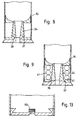
- Fig. 9 also shows the use of hollow crushable rings of plastics within the region around the column 24, as an energy absorbing means.
- expanded polystyrene can be employed, as solid rings or spheres or the like.
- a forward jacket portion 28 consists of a generally cylindrical structure 40 divided into a shot retaining portion 42 and a charge retaining portion 44 by a dividing portion 46.
- the dividing portion 46 has a member 34 projecting into the charge retaining portion to promote uniform distribution of flames from the primer (not shown).
- the dividing member further has an axially centred, annular projection 48 which extends into the shot-retaining portion 42, and a central, generally conical projection 34 which extends into the charge-retaining portion 44.
- a charge support 31 disposed between the cartridge base 13 and the jacket portion 28.
- the charge support 31 (which is separate from the jacket portion 28) comprises a platform member 32 into which the charge is received which is supported on a recoil-absorbing struture which is, in turn, carried on the base plate.
- the recoil absorbing structure comprises two toric members 116 of resilient material in each of which is an air space 41.
- a duct 22 extends axially through the cartridge base 13 and the toric members 116 to provide a flame path between a primer (not shown in Figs. 10 to 12) and the platform member 32.
- Figs. 11 and 12 illustrate alternative constructions of cartridges embodying the above described components.
- the charge support 31 could be formed integrally with the base plate of the cartridge. This is made possible since the reduction in recoil forces resulting from the invention allows the base plate to be formed from a wider range of materials (including, for example, plastics, which may, for example, be drawn or injection moulded) than hitherto possible.
- a substantially conventional base plate 13 may be used.
- a dovetail formation (as described above) may be employed to this end.
Landscapes
- Engineering & Computer Science (AREA)
- General Engineering & Computer Science (AREA)
- Toys (AREA)
- Fats And Perfumes (AREA)
- Portable Nailing Machines And Staplers (AREA)
- Aiming, Guidance, Guns With A Light Source, Armor, Camouflage, And Targets (AREA)
- Developing Agents For Electrophotography (AREA)
Claims (16)
- Patrone zum Verfeuern, umfassend eine Hülse (10) und einen Boden (13), wobei sich in der Hülse (10) eine Ladung (14), zumindest ein Geschoß (42) vor der Ladung (14) und ein Zwischenraum zwischen dem Boden und der Ladung (14) befindet, wobei der Zwischenraum zumindest teilweise von einem Ladungsträger (31) eingenommen wird, der die Ladung (14) vom Boden (13) trennt, wobei beim Abfeuern der Patrone der Ladungsträger (31) Verformung durch Zusammendrücken erfährt, dadurch gekennzeichnet, daß der Ladungsträger (31) eine oder mehrere hohle, luftgefüllte Formationen (116) umfaßt, die beim Abfeuern der Patrone elastische oder Zerdrückungsverformung erfahren.
- Patrone zum Verfeuern nach Anspruch 1, bei der die hohlen luftgefüllten Formationen (116) eine Vielzahl von Formationen mit rohrförmigem Querschnitt umfassen.
- Patrone zum Verfeuern nach Anspruch 2, bei der die Formationen (116) zwischen einem die Ladung (14) berührenden Plattformelement (32) und dem Boden (13) der Patrone angeordnet sind.
- Patrone zum Verfeuern nach Anspruch 3, bei der die zwei oder mehreren Ausbildungen (116) in einer Linie zwischen dem Plattformelement (32) und dem Boden angeordnet sind.
- Patrone zum Verfeuern nach Anspruch 4, bei der entweder zwei oder drei Formationen (41) zwischen dem Boden (13) und dem Plattformelement (32) angeordnet sind.
- Patrone zum Verfeuern nach einem der vorangegangenen Ansprüche, bei der der Ladungsträger ein Spritzgußformkörper aus Kunststoffmaterial ist.
- Patrone zum Verfeuern nach einem der vorangegangenen Ansprüche, bei der der Ladungsträger einstückig mit dem Boden der Patrone verbunden ist.
- Patrone zum Verfeuern nach einem der Ansprüche 1 bis 6, bei der der Ladungsträger eine diskrete Komponente ist, die in den Körper eingesetzt ist, wobei Haltemittel (37; 50) vorgesehen sind, um sie darin zu halten.
- Patrone zum Verfeuern nach Anspruch 8, bei der das Haltemittel ineinander verriegelnde Formationen (39) auf dem Ladungsträger und auf dem Boden (13) der Patrone umfaßt.
- Patrone zum Verfeuern nach Anspruch 8, bei der das Haltemittel einen Bereich mit verringertem Durchmesser (50) des Körpers (10) der Patrone umfaßt.
- Patrone zum Verfeuern nach einem der vorangegangenen Ansprüche, umfassend einen Mantelabschnitt (28) innerhalb der Hülse (10), wobei der Mantelabschnitt (28) eine Trennwand (46) aufweist, die zwischen der Ladung (14) und zumindest einem Geschoß (42) angeordnet ist.
- Patrone zum Verfeuern nach Anspruch 11, bei der die Trennwand (46) eine Ausbildung (34) aufweist, die in die Ladung (14) ragt, um für gleichmäßige Verteilung der Verbrennung darin zu sorgen.
- Patrone zum Verfeuern nach Anspruch 11 oder 12, in der der Mantelabschnitt (28) einen im allgemeinen zylindrischen Schrothalteabschnitt aufweist, der sich von der rennwand (46) nach vorne erstreckt.
- Patrone zum Verfeuern nach einem der Ansprüche 11 bis 13, in der der Mantelabschnitt (28) innerhalb der Hülse satt an der Patrone anliegt.
- Patrone zum Verfeuern nach Anspruch 14, bei der ein Zündhütchen (12) im Boden (13) der Patrone angeordnet ist, wobei sich ein Kanal (22) durch den Ladungsträger (30) hindurch erstreckt, um Flammen vom Zündhütchen (12) zur Ladung (14) hin zu lenken.
- Patrone zum Verfeuern nach Anspruch 15, bei der sich der Kanal (22) zum Zündhütchen (12) hin verjüngt.
Applications Claiming Priority (3)
| Application Number | Priority Date | Filing Date | Title |
|---|---|---|---|
| GB9321016 | 1993-10-12 | ||
| GB939321016A GB9321016D0 (en) | 1993-10-12 | 1993-10-12 | Recoil reducer for cartridges or other ammunition |
| PCT/GB1994/002228 WO1995010752A1 (en) | 1993-10-12 | 1994-10-12 | Recoil reducer wad for shotgun ammunition |
Publications (2)
| Publication Number | Publication Date |
|---|---|
| EP0723649A1 EP0723649A1 (de) | 1996-07-31 |
| EP0723649B1 true EP0723649B1 (de) | 1998-06-24 |
Family
ID=10743391
Family Applications (1)
| Application Number | Title | Priority Date | Filing Date |
|---|---|---|---|
| EP94928977A Expired - Lifetime EP0723649B1 (de) | 1993-10-12 | 1994-10-12 | Propfen für schrotpatronen zur verminderung des rückstosses |
Country Status (8)
| Country | Link |
|---|---|
| EP (1) | EP0723649B1 (de) |
| CN (1) | CN1159222A (de) |
| AU (1) | AU676095B2 (de) |
| CA (1) | CA2173968A1 (de) |
| DE (1) | DE69411279D1 (de) |
| ES (1) | ES2121232T3 (de) |
| GB (1) | GB9321016D0 (de) |
| WO (1) | WO1995010752A1 (de) |
Families Citing this family (6)
| Publication number | Priority date | Publication date | Assignee | Title |
|---|---|---|---|---|
| MX2011004500A (es) | 2008-10-27 | 2011-07-19 | Ra Brands Llc | Taco con camara de ignicion. |
| US8800449B2 (en) | 2008-10-27 | 2014-08-12 | Ra Brands, L.L.C. | Wad with ignition chamber |
| US8555785B2 (en) | 2009-02-02 | 2013-10-15 | Ra Brands, L.L.C. | Shotshell wad with shot confinement feature |
| US9360223B1 (en) | 2013-03-15 | 2016-06-07 | Vista Outdoor Operations Llc | High velocity ignition system for ammunition |
| WO2014144104A2 (en) | 2013-03-15 | 2014-09-18 | Alliant Techsystems Inc. | Combination gas operated rifle and subsonic cartridge |
| IT201900020288A1 (it) * | 2019-11-04 | 2021-05-04 | Sullivan Costi | Dispositivo per l'assorbimento della retrospinta di sparo in un'arma da fuoco |
Family Cites Families (14)
| Publication number | Priority date | Publication date | Assignee | Title |
|---|---|---|---|---|
| DE78438C (de) * | F. KRUG, Halberstadt, Hohe Weg 11 | Schrotpatrone mit Papierhülse und Dichtungspfropfen | ||
| DE306951C (de) * | ||||
| GB191015517A (en) * | 1910-06-28 | 1911-06-28 | Gottlob Emmanuel Loeble | Improvements in Cartridges. |
| FR1116967A (fr) * | 1954-12-31 | 1956-05-15 | Bourre semi-pneumatique en matière plastique pour cartouches de chasse | |
| FR1186659A (fr) * | 1957-11-22 | 1959-08-31 | Rhone Alpes Soc Ind | Bourre pour munitions d'armes à feu |
| AU422052B2 (en) * | 1966-11-28 | 1972-03-03 | Wad column | |
| FR1454931A (fr) * | 1964-12-07 | 1966-10-07 | Remington Arms Co Inc | élément réglant le groupement des plombs d'une cartouche |
| US3359906A (en) * | 1965-12-20 | 1967-12-26 | Herter Inc S | Shotshell base wad |
| DE1453837B2 (de) * | 1965-12-28 | 1976-04-22 | Dynamit Nobel Ag, 5210 Troisdorf | Artilleriekartusche |
| US3669023A (en) * | 1969-07-01 | 1972-06-13 | Olin Mathieson | Shot protector |
| ZA78670B (en) * | 1978-02-03 | 1979-11-28 | Andre Theodor Dreyer | Shotshells |
| DE3241149C2 (de) * | 1982-11-08 | 1984-12-20 | Wilhelm Brenneke Kg Fabrikation Von Jagdgeschossen, 3012 Langenhagen | Flintenlaufgeschoß |
| US4805535A (en) * | 1987-05-13 | 1989-02-21 | Marcon Robert V | Projectile |
| IL92941A0 (en) * | 1989-01-04 | 1990-09-17 | Piepenbrock Pyrotechnik Gmbh | Training cartridge for recoilless defense weapons |
-
1993
- 1993-10-12 GB GB939321016A patent/GB9321016D0/en active Pending
-
1994
- 1994-10-12 ES ES94928977T patent/ES2121232T3/es not_active Expired - Lifetime
- 1994-10-12 CA CA 2173968 patent/CA2173968A1/en not_active Abandoned
- 1994-10-12 AU AU78198/94A patent/AU676095B2/en not_active Ceased
- 1994-10-12 CN CN 94194443 patent/CN1159222A/zh active Pending
- 1994-10-12 WO PCT/GB1994/002228 patent/WO1995010752A1/en not_active Ceased
- 1994-10-12 DE DE69411279T patent/DE69411279D1/de not_active Expired - Lifetime
- 1994-10-12 EP EP94928977A patent/EP0723649B1/de not_active Expired - Lifetime
Also Published As
| Publication number | Publication date |
|---|---|
| EP0723649A1 (de) | 1996-07-31 |
| CA2173968A1 (en) | 1995-04-20 |
| GB9321016D0 (en) | 1993-12-01 |
| CN1159222A (zh) | 1997-09-10 |
| AU676095B2 (en) | 1997-02-27 |
| WO1995010752A1 (en) | 1995-04-20 |
| AU7819894A (en) | 1995-05-04 |
| ES2121232T3 (es) | 1998-11-16 |
| DE69411279D1 (de) | 1998-07-30 |
Similar Documents
| Publication | Publication Date | Title |
|---|---|---|
| US4970959A (en) | Collapsible basewad | |
| US3496869A (en) | Sabot projectile | |
| US6782828B2 (en) | Pliant firearm projectiles | |
| US4958567A (en) | Training cartridge with improved case for fixing propellant position in powder chamber | |
| US4653404A (en) | High velocity notched ammunition sabot | |
| JP3388640B2 (ja) | 縮射用弾丸のための放出可能な装弾筒 | |
| CA2360239C (en) | Marker projectile | |
| EP0616684A1 (de) | Übungsgeschoss | |
| US4805535A (en) | Projectile | |
| US3507220A (en) | Ammunition round | |
| US4172420A (en) | Propellant charge for recoilless weapons | |
| EP0723649B1 (de) | Propfen für schrotpatronen zur verminderung des rückstosses | |
| US5710391A (en) | Recoil reducer wad for ammunition | |
| US5173571A (en) | Projectile guide for telescoped ammunition | |
| US20050115392A1 (en) | Countermass weapon | |
| RU2492408C1 (ru) | Травматический патрон для бесствольного оружия | |
| KR100331776B1 (ko) | 소구경발사체를위한부품들이조절분리되는탄환발사장치 | |
| US3720171A (en) | Plastic shot shell wad | |
| US5063852A (en) | Forward full caliber control tube for a cased telescoped ammunition round | |
| US6490959B2 (en) | Recoilless telescoping barrel gun | |
| TW202400958A (zh) | 玩具榴彈及其彈丸裝填裝置 | |
| RU2075033C1 (ru) | Активно-реактивный снаряд | |
| RU2080552C1 (ru) | Пуля омельяненко для гладкоствольного оружия | |
| CA1142782A (en) | Device for launching of a projectile from a launching tube opened at its two ends | |
| RU2458317C1 (ru) | Пуля "бабочка подкалиберная" и патрон для гладкоствольного оружия |
Legal Events
| Date | Code | Title | Description |
|---|---|---|---|
| PUAI | Public reference made under article 153(3) epc to a published international application that has entered the european phase |
Free format text: ORIGINAL CODE: 0009012 |
|
| 17P | Request for examination filed |
Effective date: 19960502 |
|
| AK | Designated contracting states |
Kind code of ref document: A1 Designated state(s): BE DE DK ES FR GB IT SE |
|
| 17Q | First examination report despatched |
Effective date: 19960813 |
|
| GRAG | Despatch of communication of intention to grant |
Free format text: ORIGINAL CODE: EPIDOS AGRA |
|
| GRAG | Despatch of communication of intention to grant |
Free format text: ORIGINAL CODE: EPIDOS AGRA |
|
| GRAH | Despatch of communication of intention to grant a patent |
Free format text: ORIGINAL CODE: EPIDOS IGRA |
|
| GRAH | Despatch of communication of intention to grant a patent |
Free format text: ORIGINAL CODE: EPIDOS IGRA |
|
| GRAA | (expected) grant |
Free format text: ORIGINAL CODE: 0009210 |
|
| AK | Designated contracting states |
Kind code of ref document: B1 Designated state(s): BE DE DK ES FR GB IT SE |
|
| PG25 | Lapsed in a contracting state [announced via postgrant information from national office to epo] |
Ref country code: BE Free format text: LAPSE BECAUSE OF FAILURE TO SUBMIT A TRANSLATION OF THE DESCRIPTION OR TO PAY THE FEE WITHIN THE PRESCRIBED TIME-LIMIT Effective date: 19980624 |
|
| REF | Corresponds to: |
Ref document number: 69411279 Country of ref document: DE Date of ref document: 19980730 |
|
| PG25 | Lapsed in a contracting state [announced via postgrant information from national office to epo] |
Ref country code: SE Free format text: LAPSE BECAUSE OF FAILURE TO SUBMIT A TRANSLATION OF THE DESCRIPTION OR TO PAY THE FEE WITHIN THE PRESCRIBED TIME-LIMIT Effective date: 19980924 Ref country code: DK Free format text: LAPSE BECAUSE OF FAILURE TO SUBMIT A TRANSLATION OF THE DESCRIPTION OR TO PAY THE FEE WITHIN THE PRESCRIBED TIME-LIMIT Effective date: 19980924 |
|
| PG25 | Lapsed in a contracting state [announced via postgrant information from national office to epo] |
Ref country code: DE Free format text: LAPSE BECAUSE OF FAILURE TO SUBMIT A TRANSLATION OF THE DESCRIPTION OR TO PAY THE FEE WITHIN THE PRESCRIBED TIME-LIMIT Effective date: 19980925 |
|
| ET | Fr: translation filed | ||
| REG | Reference to a national code |
Ref country code: ES Ref legal event code: FG2A Ref document number: 2121232 Country of ref document: ES Kind code of ref document: T3 |
|
| PLBE | No opposition filed within time limit |
Free format text: ORIGINAL CODE: 0009261 |
|
| STAA | Information on the status of an ep patent application or granted ep patent |
Free format text: STATUS: NO OPPOSITION FILED WITHIN TIME LIMIT |
|
| 26N | No opposition filed | ||
| REG | Reference to a national code |
Ref country code: GB Ref legal event code: IF02 |
|
| PGFP | Annual fee paid to national office [announced via postgrant information from national office to epo] |
Ref country code: GB Payment date: 20040205 Year of fee payment: 10 |
|
| PGFP | Annual fee paid to national office [announced via postgrant information from national office to epo] |
Ref country code: ES Payment date: 20040211 Year of fee payment: 10 |
|
| PGFP | Annual fee paid to national office [announced via postgrant information from national office to epo] |
Ref country code: FR Payment date: 20040220 Year of fee payment: 10 |
|
| PG25 | Lapsed in a contracting state [announced via postgrant information from national office to epo] |
Ref country code: GB Free format text: LAPSE BECAUSE OF NON-PAYMENT OF DUE FEES Effective date: 20041012 |
|
| PG25 | Lapsed in a contracting state [announced via postgrant information from national office to epo] |
Ref country code: ES Free format text: LAPSE BECAUSE OF NON-PAYMENT OF DUE FEES Effective date: 20041013 |
|
| GBPC | Gb: european patent ceased through non-payment of renewal fee |
Effective date: 20041012 |
|
| PG25 | Lapsed in a contracting state [announced via postgrant information from national office to epo] |
Ref country code: FR Free format text: LAPSE BECAUSE OF NON-PAYMENT OF DUE FEES Effective date: 20050630 |
|
| REG | Reference to a national code |
Ref country code: FR Ref legal event code: ST |
|
| PG25 | Lapsed in a contracting state [announced via postgrant information from national office to epo] |
Ref country code: IT Free format text: LAPSE BECAUSE OF NON-PAYMENT OF DUE FEES Effective date: 20051012 |
|
| REG | Reference to a national code |
Ref country code: ES Ref legal event code: FD2A Effective date: 20041013 |