EP0723510B1 - Bicycle torque coupling - Google Patents
Bicycle torque coupling Download PDFInfo
- Publication number
- EP0723510B1 EP0723510B1 EP94922120A EP94922120A EP0723510B1 EP 0723510 B1 EP0723510 B1 EP 0723510B1 EP 94922120 A EP94922120 A EP 94922120A EP 94922120 A EP94922120 A EP 94922120A EP 0723510 B1 EP0723510 B1 EP 0723510B1
- Authority
- EP
- European Patent Office
- Prior art keywords
- lug
- teeth
- face
- nut
- frame
- Prior art date
- Legal status (The legal status is an assumption and is not a legal conclusion. Google has not performed a legal analysis and makes no representation as to the accuracy of the status listed.)
- Expired - Lifetime
Links
Images

Classifications
-
- B—PERFORMING OPERATIONS; TRANSPORTING
- B62—LAND VEHICLES FOR TRAVELLING OTHERWISE THAN ON RAILS
- B62K—CYCLES; CYCLE FRAMES; CYCLE STEERING DEVICES; RIDER-OPERATED TERMINAL CONTROLS SPECIALLY ADAPTED FOR CYCLES; CYCLE AXLE SUSPENSIONS; CYCLE SIDECARS, FORECARS, OR THE LIKE
- B62K15/00—Collapsible or foldable cycles
-
- B—PERFORMING OPERATIONS; TRANSPORTING
- B62—LAND VEHICLES FOR TRAVELLING OTHERWISE THAN ON RAILS
- B62K—CYCLES; CYCLE FRAMES; CYCLE STEERING DEVICES; RIDER-OPERATED TERMINAL CONTROLS SPECIALLY ADAPTED FOR CYCLES; CYCLE AXLE SUSPENSIONS; CYCLE SIDECARS, FORECARS, OR THE LIKE
- B62K15/00—Collapsible or foldable cycles
- B62K2015/001—Frames adapted to be easily dismantled
Definitions
- the following invention relates generally to bicycles which have frames dividable and recombinable through a coupling and a method and apparatus for storing such a bicycle. More specifically, this invention relates to a bicycle frame tube coupling which rigidly joins pieces of the frame or any two portions of a shaft together, and which facilitates storing of the entire bicycle in a case which complies with size requirements of common carriers for non-oversized luggage.
- the patent to Brenner teaches a collapsible bicycle that uses standard plumbing pipe unions, adapted to fit on three places of a bicycle.
- this invention may be used in a similar fashion to Brenner, it is different in many ways, the most important of which are: first, the coupling of this invention uses a removable shoulder on a lug end, not a permanently fixed flanged end; second, this invention is for a coupling that has specialized clutch teeth cut onto engaging faces instead of flat surfaces, or a mere alignment pin; third, this invention does not involve the adaptation of three, standard, off. the shelf, plumbing parts to fit a bicycle. It is for a custom made, light weight, strong, aerodynamic, torque transmitting coupling of which only two are needed to adapt a bicycle for frame subdivision.
- the removable shoulder feature of one coupling of this invention adds positive things to the coupling over the teachings of Brenner.
- Brenner teaches no such provision.
- a removable shoulder can also be easily replaced.
- the nut can as well, because it is the removable shoulder that keeps it on and not a permanently fixed flange.
- the coupling taught by Brenner would require the melting of solder or cutting to be able to remove and replace the nut if damaged, or to replace the whole coupling end if the flange were damaged.
- differential thread in an alternative embodiment of the coupling of this invention is also distinguishable from the teachings of Brenner.
- the differential thread by its nature, allows a tighter fit in the coupling teeth when the nut is tightened. It also eliminates the use of a flange on the coupling nut to draw the lug ends together.
- the tube accepting ends of the coupling are also much improved over the teachings of Brenner.
- the lug ends of this invention taper thinner on the outer diameter towards the outside ends and are angle cut on two sides to produce points 180 degrees from each other. These two attributes allow this coupling to better distribute stresses put on the tube connection points during bicycle use.
- the taper gradually reduces the cross sectional area, and the angle cut spreads the intersection point of lug and tube out over a longer distance so it is not all in the same plane which lies perpendicular to the polar axis of the frame tube.
- the lugs taught by Brenner were not tapered and ended bluntly on the ends.
- One primary feature of the invention is a coupling that can join bicycle frame tubes end to end with minimal weight addition, and preserve the original geometry and stiffness of the frame. Preservation of such features is very important to avid cyclists.
- the coupling has two lugs that join together with a coupling nut and replaces a small segment of tubing cut from the original frame. Both lugs have inner faces cut with clutch teeth that interlock when the coupling nut pulls them together.
- the design is compact, light and strong.
- the frame can be divided, allowing the resulting pieces to fit in a case having dimensions acceptable for handling by airlines and other carriers without requiring additional changes or other difficulties.
- additional quick connect cable clips are installed as well, according to this invention, an entire standard bicycle can be broken down and packaged in the case of this invention.
- the case is chosen to fit the bicycle's wheel diameters and with a maximum girth while still comprising not more than 62 total linear inches (157.5 cm) of size.
- the bicycle can later be reassembled to yield a bicycle that rides exactly like the original, with no loss of the original frame geometry or stiffness, two things which are very important to avid cyclists.
- the invention is directed to a connector for releasably joining ends of a bicycle frame tube, the connector comprising in combination the features disclosed in the attached claim 1.
- the system includes a coupling (50) for dividing a frame (60) of the bicycle into separate pieces (A, B) and a case (100) for storing and containing the individual parts of the bicycle.
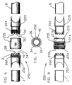
- the coupling (50) includes a threaded lug (2), a removable-shoulder lug (9), a coupling nut (5) and a removable shoulder (4) with a groove (8) providing one form of a means to attach the shoulder (4) onto the removable shoulder lug (9).
- the lugs (2, 9) are bored to fit over ends (1, 11) of a frame tube up to inner shoulders (14, 17) and have truncated, tapered dutch teeth (3, 7) cut on their adjacent ends.
- the teeth (3, 7) on both lugs (2, 9) are identical and are radially oriented with tapered side surfaces (34), top surfaces (32) and bottom gap surfaces (36).
- Each tooth (3, 7) is angled from vertical with an outer extent of the top surface (32) closer to the opposite lug (9, 2) than an inner extent of the bottom surface (36).
- Each bottom surface (36) is angled from vertical with an inner extent of the bottom surface (36) closer to the opposite lug (9, 2) than an outer extent of the bottom surface (36).
- the effect is to produce tooth tops (32) and gap bottoms (36), that are essentially rectangular in nature, roughly the same size, and approximately parallel to one another.
- This gap (38) configuration facilitates manufacture in that the gap (38) exhibits an easily
- the bottom surface (36) is angled approximately 30 degrees from vertical.
- the top surface (32) is angled approximately 30 degrees from vertical.
- the side surfaces (34) exhibit an approximately equilateral triangular form.
- the teeth/gap arrangement produces teeth (3, 7) that allow full contact on all sides when meshed together. Truncation of such teeth (3, 7) at a tip (40) at an outer extent of the top surfaces (32) further prevents the teeth (3, 7) from bottoming out in the mating gaps (38) of the opposing lug (9, 2), eliminating all backlash when the coupling nut (5) is tightened. Backlash is also prevented by the taper of the teeth (3, 7). An angle of taper of the teeth is selected to provide the teeth (3, 7) with high resistance to torque and yet ease of intermeshing. The truncated tip (40) also facilitates future tightening to compensate for potential wear through repeated use. Many common manufacturing methods can be utilized to create the clutch teeth (3, 7). One method which has proven successful involves turning the lugs (2, 9) on a lathe and then machining the teeth (3, 7) with an appropriate tool.
- the tube accepting ends of the lugs (2, 9) have angles (12, 13) cut to form two points 180 degrees opposite each other, and the lugs' outer diameters taper to cause the lugs (2, 9) to be thinner approaching those points.
- the coupling parts (2, 4, 5, 9) should be made from materials that will be as strong as the frame tubes (1, 11) when machined to the desired thickness and that will allow attachment of the coupling (50) by some means compatible with both materials, such as brazing, silver brazing, welding, adhesive bonding, etc., so the combination of tubes (1, 11) and couplings (50) will transmit all normal forces acting on the bicycle frame (60) without failure.
- materials such as brazing, silver brazing, welding, adhesive bonding, etc.
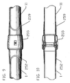
- a differential thread torque coupling (250) is shown.
- the differential coupling (250) of this invention is much like the above description of the coupling (50) except that there is no removable shoulder (4), the smaller outer diameter lug (259) replaces the removable shoulder lug (9) and has no groove (8) in it, and the coupling nut (255) is cut with two different thread pitches to match those of the two lugs (252, 259), eliminating the shoulder that the retaining ring (4) is butted up against in the preferred embodiment.
- a larger outer diameter lug (252) and a smaller outer diameter lug (259) are provided. Both lugs (252, 259) include threads (262, 264) on the outer surface.
- the smaller diameter lug (259) preferably has threads (264) which are more fine than the threads (262) of the larger diameter lug (252).
- the nut (255) has threads (272, 274) on its inner surface (270).
- the inner surface (270) includes a lesser diameter portion (276) and a greater diameter portion (278),
- the greater diameter portion (278) supports threads (272) of similar pitch to the threads (262) of the larger diameter lug (252).
- the lesser diameter portion (276) supports threads (274) of similar pitch to the threads (264) of the smaller diameter lug (259).
- a nut shoulder (277) separates the two portions (276, 278) of the inner surface (270).
- the shoulder (277) prevents the larger diameter lug (252) from damaging the threads (274).
- a lug shoulder (258) is located on the smaller diameter lug (259) and prevents the nut (255) from traveling off of the smaller diameter lug (259) and onto the tube (11). When the nut (255) is tightened, the nut (255) moves onto the larger diameter lug (252) faster than it moves off of the smaller diameter lug (259), thus compressing the lugs (252, 259) together.
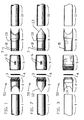
- FIG. 11 details of a process to determine the size of a case (100) needed for packaging a bicycle for travel that does not exceed the 62 inch (157,5 cm) total linear dimension limit typical of U.S. and international airlines is shown.
- This process determines what pieces a bicycle will need to be divided into to fit within such a case (100) including precise division of the frame (60) as well as additional case (100) features that will make a case (100) more versatile, and a method of packing the bicycle pieces so that all of the bicycle will safely fit in the case (100).
- first one has to determine exactly what dimensions the chosen case (100) can have. Since wheels (62, 63) of the bicycle do not normally break down, a case (100) for a whole bicycle has to be large enough to include the wheel's heights and widths with room for other bicycle pieces somewhere in between.
- a slightly larger wheel (62, 63) would make the case (100) larger in height and width, and thinner in girth.
- a smaller wheel (62, 63) would allow the opposite so long as the size of the pieces (A, B) the frame (60) can be divided into is considered.
- a standard bicycle's wheel size does not vary so greatly as to make a noticeable difference in the way a bicycle's frame pieces (A, B) and wheels (62, 63) can be divided and packaged in a case. The remainder of the bicycle parts, removed from the frame (60), fit in between the wheels (62, 63) and frame pieces (A, B) in a properly proportioned 62 inch total linear dimension case.
- a standard bicycle generally is a bicycle having a frame composed of individual tubes and fairly standard “700C” wheels such as that shown in figure 19.
- “700C” wheels have an approximately 26 inch (66.04 cm) diameter when a tire thereon is deflated.
- Other common names for such a bicycle are “racing” or “touring” bicycles.
- “Mountain bikes” having wider wheels of similar diameter and modified handlebars are also contemplated as within the definition of a standard bicycle. While frame sizes vary, the wheels are sized fairly standard at approximately 26 inches (66.04 cm) in diameter.
- the couplings (50, 250) make it possible to break the frame (60) down into smaller pieces (A, B) for packing, and then reassemble the pieces (A, B), putting various standard components (80) of the bicycle back on the frame (60), to produce a bicycle that rides exactly like the original.
- a front piece (A) would likely include a head tube (29) of the frame (60) and a rear piece (B) would likely include a bottom bracket (30) of the frame (60).
- Precise location of the couplings (50, 250) allows the frame (60) to be divided into as few pieces as possible that will still fit inside the case (100).
- the frame (60) is only divided into two pieces.
- these templates (T) must be adjusted on the front and rear anticipated sections of the bicycle until each component (80) that cannot or will not be removed for packing the-bicycle in a case (100) is totally within the area defined by at least one template (T) (see figure 12).
- This can include, but is not limited to: (inside the dotted area on the left in figure 12) the top of the head-set (20) the tip of the forward fork (18), and (inside the dotted area on the right in figure 12), the entire seat tube (22), the lowest tip of the rear wheel drop out (23) where the derailleur connects, and the crank set assembly (24).
- the overlapping areas (19, 21) of the templates (T) on the top tube (96) and down tubes (98) in figure 12 identify where the templates (T) overlap on those tubes (96, 98). This is where the couplings (50, 250) are to be inserted and where the center lines of the couplings (50, 250) must be after installation.
- area (21) is very small and requires exact placement of the couplings (50, 250), while area (19) is quite large and will allow for much adjustment in the placement of the couplings (50, 250).
- Figures 13 and 14 show the couplings (50, 250) installed within the overlapping areas (19, 21). In this example, the threaded lugs (2) are in figure 13, and the removable shoulder lugs are in figure 14. Again, note the position of the coupling (50) center lines within the overlapping areas (19, 21) of the templates (T).
- tubing (1, 11) that will be replaced by the coupling (50, 250), from inner shoulder (14) to inner shoulder (17) (figure 3) of the lugs (2 and 9) (figure 1) should be cut out, keeping in mind positions of previously brazed on lugs, cable guides, etc. that may interfere with the couplings.
- New tubes (1, 11) can also be utilized to replace the previous tubes (96, 98).
- the frame (60) is marked within the overlap area and an appropriate portion of the tube (96, 98) is removed to preserve the original frame geometry. If the mark is too close to an obstruction on the tube (1, 11) it should be moved to have 2 inches of clearance. Repositioning or replacing some of these parts may be necessary.
- methods of securing the lugs (2, 9) to the frame vary, depending on the material the lugs (2, 9) and frame (60) are made of. In one case, when the couplings (50) are made from stainless steel the couplings (50) can be, silver brazed on to carbon steel frame tubes (1, 11).
- each coupling nut (5) is slid onto its mating removable-shoulder lug (9) until the removable shoulder (4) can be put on.
- retaining rings in a groove (8) have been used with success, but the removable shoulder (4) could be one of many configurations with multiple attachment methods, such as threading, set screws, slots, pins, etc.
- the removable shoulder (4) functions with the coupling nut (5) to pull frame pieces (A, B) together.
- a tapered shoulder (10) is located on the removable lug (9) to meet a tapered shoulder (16) in the coupling nut (5). This prevents the nut (5), when unscrewed, from falling off the back side of the lug (9) and scratching the frame paint.
- the nut (5) and the removable shoulder (4) are also easily replaceable if they get damaged.
- the coupling nut (5) threads onto the threaded lug (2) and pulls the removable-shoulder lug (9) axially by shoulder (15) of the coupling nut (5) engaging the removable shoulder (4). This interlocks the clutch teeth (3, 7).
- a force transmitting union equal in strength or greater than that of the original tube (96, 98), is formed. If the coupling's teeth (3, 7) do wear, further tightening of the coupling nut (5) will take up any backlash with a negligible change in the frame tube (96, 98) length.
- the coupling nut (255) begins totally screwed onto the fine threaded lug (255).
- the tapered teeth (3, 7) of the course threaded lug and of the fine threaded lug (259) are firmly meshed together.
- the nut (255) is started onto the course threaded lug (252). It threads onto that lug (252) faster than it threads off of the fine threaded lug (259), thus pulling the two lugs (252, 259) together. Tightening with a spanner wrench will, as before, form a tube union with strength equal to or greater than the original tube (96, 98). If the teeth (3, 7) wear, they can be drawn further together by tightening the coupling nut (255) more.
- the fact that the teeth can be pressed together with zero backlash also helps to prevent the coupling from wiggling and working the coupling nut loose during hard use.
- Another object of this invention of to provide a differential thread coupling to securely hold together frame tube portions connected to lugs of the coupling.
Landscapes
- Engineering & Computer Science (AREA)
- Mechanical Engineering (AREA)
- Mutual Connection Of Rods And Tubes (AREA)
- Automatic Cycles, And Cycles In General (AREA)
Description
| INVENTOR | PATENT NO. | ISSUE DATE |
| Jankowski | 3,304,099 | |
| Hearn | 3,463,228 | August 26, 1969 |
| Schultenkamper, et al. | 4,053,248 | October 11,1977 |
| Brenner | 4,252,335 | February 1981 |
| Hon | 4,462,606 | July 31, 1984 |
| OTHER PRIOR ART | ||
| "Marcellin | FR 992,681 | 11 July 1951 |
Claims (7)
- A connector (50) for releasably joining ends of a bicycle frame tube together to facilitate disassembly and reassembly of a bicycle frame, the connector comprising in combination:characterised in thata first lug (2, 252) fixedly attachable to and overlying a first end of a first frame tube (1) to be joined,a second lug (9, 259) fixedly attachable to and overlying a second end of a second frame tube (11) to be joined,means to apply a compressive force compressing said first lug (2) against said second lug (9), said compressive force applying means operatively coupled between said first lug and said second lug, said compressive force applying means including a coupling nut (5, 255) connected to said second lug (11) in a manner allowing rotation therebetween, said coupling nut having an inner bore with threads thereon, and said first lug (2) having threads (262) on an exterior thereof complemental to said threads (278) on said coupling nut (5),means to resist axial translation of said coupling nut completely off of said second lug and onto said second frame tube (11) to which said second lug (9) is attached,means to resist rotation of one of said lugs (2,9) with respect to another of said lugs; said rotation resisting means including intermeshing clutch teeth (3) formed on first and second mating faces of each lug which engage each other when drawn together by the means to apply compressive force,whereby said first frame tube (1) and said second frame tube (11) can be rigidly joined together,the intermeshing clutch teeth comprising a plurality of teeth (3,7) oriented on said first mating face and said second mating face, said teeth spaced from each other by gaps (36) therebetween sized to receive teeth of an opposite said face,said teeth each including two sides (34), one on either side of said teeth, said sides tapering at an angle non-perpendicular to the plane in which said first face abuts said second face, each said tooth having a width between said two sides which decreases as said tooth extends away from said mating face to which said tooth is attached, such that said teeth exhibit tapered sides facilitating intermeshing of said teeth of one said face within said gaps of an opposite said face,
said first mating face-teeth have a top surface (32) which is adjacent a bottom gap surface (36) between said teeth of said second mating face when said first face abuts said second face and which slopes at a first angle non-parallel to a plane in which said first face abuts said second face and said gaps having said bottom gap surface (2) which slopes at a second angle complemental to said first angle such that said teeth can be located within said gaps when said first face abuts said second face. - The connector of claim 1 wherein the means to resist axial translation of the coupling nut includes said second lug having a shoulder (10) with an exterior diameter greater than a portion (16) of said inner bore of said coupling nut (5), whereby said coupling nut abuts said shoulder (10) of said second lug (9) when translated axially toward the second frame tube,
said axial translation resisting means including also said second lug (9) having a second shoulder (4) with an exterior diameter greater than a portion of said inner bore of said coupling nut, said second shoulder closer to the first frame tube than said portion of said inner bore of said coupling nut (5), whereby said coupling nut is prevented from translation off of said second lug, said second shoulder (4) being removably connected to said second lug (9). - The connector of claim 1 wherein the means for drawing together said lugs (2,9) is threads (262, 264, 272, 274) on outer surfaces of both lugs and an inner surface of said nut, said threaded outer surfaces (262, 264) of said lugs having different diameters and said inner surface of said nut having two different diameters (272, 274), a first diameter complemental to an outer diameter of said first lug (2) and a second diameter complemental to the outer diameter of said second lug (9); whereby said nut (5) is prevented from threading onto said larger diameter lug beyond a greater diameter portion of said inner surface and said threads of said smaller diameter lug are prevented from contacting threads of a larger diameter portion of said inner surface of said nut.
- The connector of claim 3 wherein said threads (262) of said first lug having a different pitch than threads (264) of said second lug, whereby a differential threading arrangement is provided, the rotation of the nut causing said lugs (2,9) to be drawn toward each other.
- The connector of any of the preceding claims wherein each lug (2, 9) includes a tube accepting end forming an attached edge at which said lug is fixedly attached to one of the frame tubes (1, 11), said attached edge (12, 13) being oriented non-perpendicular to a long axis of the frame tube to which said lug is attached, whereby forces applied at said attached edge are distributed somewhat along a length of the frame tube.
- The connector of claim 5 wherein the tube accepting ends of the lugs (2, 9) have angles (12, 13) cut to form two points 180 degrees opposite each other on each frame tube (1, 11) to be joined.
- The connector of claim 5 or 6 wherein each said lug includes an exterior circumference which tapers to a lesser size as said lug extends toward said attached edge thereof, whereby said lug exhibits a lesser exterior diameter adjacent said attached edge than at other portions of said lug.
Applications Claiming Priority (5)
| Application Number | Priority Date | Filing Date | Title |
|---|---|---|---|
| US08/089,108 US5431507A (en) | 1993-07-12 | 1993-07-12 | Bicycle torque coupling |
| US89108 | 1993-07-12 | ||
| US08/122,368 US5586652A (en) | 1993-07-12 | 1993-09-16 | Bicycle torque coupling |
| US122368 | 1993-09-16 | ||
| PCT/US1994/007731 WO1995002534A1 (en) | 1993-07-12 | 1994-07-12 | Bicycle torque coupling |
Publications (3)
| Publication Number | Publication Date |
|---|---|
| EP0723510A1 EP0723510A1 (en) | 1996-07-31 |
| EP0723510A4 EP0723510A4 (en) | 1998-11-25 |
| EP0723510B1 true EP0723510B1 (en) | 2003-04-09 |
Family
ID=26780256
Family Applications (1)
| Application Number | Title | Priority Date | Filing Date |
|---|---|---|---|
| EP94922120A Expired - Lifetime EP0723510B1 (en) | 1993-07-12 | 1994-07-12 | Bicycle torque coupling |
Country Status (8)
| Country | Link |
|---|---|
| US (1) | US5586652A (en) |
| EP (1) | EP0723510B1 (en) |
| JP (1) | JP3714953B2 (en) |
| CN (1) | CN1066403C (en) |
| AU (1) | AU7257294A (en) |
| CA (1) | CA2164962C (en) |
| DE (1) | DE69432473T2 (en) |
| WO (1) | WO1995002534A1 (en) |
Cited By (3)
| Publication number | Priority date | Publication date | Assignee | Title |
|---|---|---|---|---|
| US9022731B2 (en) | 2009-11-03 | 2015-05-05 | Alessandro Seccareccia | Centrifugal ceiling fan |
| EP3085609A1 (en) | 2015-04-23 | 2016-10-26 | Pedalpower Schönstedt&Busack GbR | Positionable insertion coupling for releasably connecting bicycle frame parts |
| DE202015009489U1 (en) | 2015-04-23 | 2018-01-19 | Pedalpower Schönstedt & Busack GbR (vertretungsberechtigter Gesellschafter Harald Busack, 10317 Berlin) | Positionable Steckradkupplung for detachable connection of bicycle frame parts |
Families Citing this family (26)
| Publication number | Priority date | Publication date | Assignee | Title |
|---|---|---|---|---|
| JP3780800B2 (en) * | 2000-02-14 | 2006-05-31 | セイコーエプソン株式会社 | Image forming apparatus |
| US6688627B1 (en) | 2001-04-16 | 2004-02-10 | Ruowei Z. T. Strange | Bicycle which converts to a chair |
| US7722070B2 (en) * | 2001-09-28 | 2010-05-25 | Ritchey Designs, Inc. | System and method for connecting parts |
| ATE290979T1 (en) | 2001-09-28 | 2005-04-15 | Ritchey Designs Inc | A SYSTEM AND METHOD FOR CONNECTING PARTS |
| WO2008116077A2 (en) * | 2007-03-21 | 2008-09-25 | Hall David R | Downhole tool string component |
| US7942434B2 (en) * | 2008-05-07 | 2011-05-17 | Brian T Myers | Disengageably coupled take-apart bicycle frame |
| TWM373317U (en) * | 2009-07-24 | 2010-02-01 | Wen-Teng Lin | Bike folding structure |
| US20110057414A1 (en) * | 2009-09-08 | 2011-03-10 | West Robert V | Bike frame 143 |
| FR2953271B1 (en) * | 2009-11-27 | 2012-11-16 | Vallourec Mannesmann Oil & Gas | ASSEMBLY FOR CARRYING OUT A THREADED SEAL, METHOD FOR SCREWING AND DISCRIMINATING SUCH A SEAL AND USE OF SUCH JOINT IN AN UNDERWATER UPLINK |
| US8690689B1 (en) | 2010-10-18 | 2014-04-08 | Cornay Company Llc | Driveshaft coupling |
| DE102011122798A1 (en) | 2011-05-13 | 2013-03-28 | Pedalpower GbR (vertretungsberechtigter Gesellschafter: Harald Busack, 10965 Berlin) | Torque transmission coupling structure e.g. clutch assembly for bicycle e.g. push bike, has coupling element and receiving element whose front ends are provided with non-circular course of mating surfaces respectively |
| CN103448460A (en) * | 2012-05-30 | 2013-12-18 | 航翊科技股份有限公司 | Improved structure of carbon fiber bicycle wheel |
| US10343745B2 (en) | 2013-09-26 | 2019-07-09 | Sram, Llc | Bicycle crank arm and chainring carrier assembly |
| WO2015126367A1 (en) * | 2014-02-18 | 2015-08-27 | Cornay Company Llc | Driveshaft coupling |
| US10202162B2 (en) | 2014-03-12 | 2019-02-12 | Bert Vermeulen | System for packing a human-powerable wheeled vehicle |
| USD759572S1 (en) * | 2015-03-02 | 2016-06-21 | David Moore | Bicycle separator |
| CN105712051A (en) * | 2016-01-07 | 2016-06-29 | 武汉华星光电技术有限公司 | Detachable transmission rod and connecting mechanism thereof |
| US10392072B2 (en) | 2016-02-24 | 2019-08-27 | Bert Vermeulen | System and method for packing a human-powerable wheeled vehicle |
| ITUA20162078A1 (en) * | 2016-03-29 | 2017-09-29 | S G Compositi S R L | JOINT FOR FOLDING FRAMES OF BICYCLES AND SIMILAR VEHICLES |
| CN106741448B (en) * | 2016-10-31 | 2019-04-30 | 安徽炫风新能源科技有限公司 | A kind of foldable assembly and folded bicycle |
| US10556464B2 (en) | 2018-01-21 | 2020-02-11 | Bert Vermeulen | Spoked human-powerable vehicle wheel with user-removable hub and plurality of conical hub-to-annulus attachment elements |
| DE102018102544A1 (en) | 2018-02-05 | 2019-08-08 | Tobias Kruschhausen | Frame device for a tilting vehicle and a tilting vehicle |
| US10414460B1 (en) * | 2019-01-30 | 2019-09-17 | Azure Bike International Ltd. | Collapsible handlebar of a bicycle |
| IT201900025813A1 (en) * | 2019-12-31 | 2021-07-01 | Valerio Torre | FOLDABLE BICYCLE STRUCTURE |
| IT202000012799A1 (en) * | 2020-06-03 | 2021-12-03 | Unik Innovation Srl | QUICK ASSEMBLY FRAME FOR BICYCLE OR SIMILAR |
| DE102024129925A1 (en) * | 2024-10-15 | 2026-04-16 | Gühring KG | Modular cutting tool |
Family Cites Families (19)
| Publication number | Priority date | Publication date | Assignee | Title |
|---|---|---|---|---|
| US349678A (en) * | 1886-09-28 | Benjamin f | ||
| DE304981C (en) * | ||||
| US717684A (en) * | 1902-03-20 | 1903-01-06 | John Humphreys | Tube-splicing. |
| FR16500E (en) * | 1911-02-07 | 1913-02-06 | Jean Octave Ferdinand Sauvain | Portable folding bicycle |
| FR470768A (en) * | 1913-06-23 | 1914-09-29 | Alphonse Thomann | Improvements to folding bicycles allowing their rapid transformation for service or transport |
| US2094416A (en) * | 1936-09-04 | 1937-09-28 | William F Sheffield | Drilling shaft coupling |
| US2447956A (en) * | 1944-05-25 | 1948-08-24 | Morders Howard | Means for connecting separated parts of a bicycle frame |
| FR992681A (en) * | 1944-08-02 | 1951-10-22 | Improvements to cycles | |
| US2549264A (en) * | 1947-11-01 | 1951-04-17 | Chromium Mining And Smelting C | Electrical contact coupling for liquid cooled cable |
| US3304099A (en) * | 1965-03-30 | 1967-02-14 | Stanley H Jankowski | Knockdown bicycle frame |
| US3463228A (en) * | 1967-12-29 | 1969-08-26 | Halliburton Co | Torque resistant coupling for well tool |
| US3623753A (en) * | 1969-12-08 | 1971-11-30 | Smith International | Pipe coupling for a sealed fluid conductor |
| US3873223A (en) * | 1973-03-01 | 1975-03-25 | Charles B Caperton | Coupling means for sewer rod |
| DE2554574A1 (en) * | 1975-12-04 | 1977-06-08 | Gelenkwellenbau Gmbh | DISC COUPLING FOR CONNECTING SHAFTS |
| US4074703A (en) * | 1976-09-07 | 1978-02-21 | Caterpillar Tractor Co. | Accumulator drain |
| US4099745A (en) * | 1977-04-04 | 1978-07-11 | Cobbs James H | Drill pipe joint |
| US4252335A (en) * | 1979-07-11 | 1981-02-24 | Brenner Richard K | Collapsible bicycle |
| US4462606A (en) * | 1981-02-12 | 1984-07-31 | Hon Corporation International | Foldable and portable vehicle |
| US5154532A (en) * | 1990-02-08 | 1992-10-13 | Graco, Inc. | Reciprocating pump coupling |
-
1993
- 1993-09-16 US US08/122,368 patent/US5586652A/en not_active Expired - Lifetime
-
1994
- 1994-07-12 JP JP50464295A patent/JP3714953B2/en not_active Expired - Fee Related
- 1994-07-12 CN CN94192759A patent/CN1066403C/en not_active Expired - Fee Related
- 1994-07-12 AU AU72572/94A patent/AU7257294A/en not_active Abandoned
- 1994-07-12 EP EP94922120A patent/EP0723510B1/en not_active Expired - Lifetime
- 1994-07-12 DE DE69432473T patent/DE69432473T2/en not_active Expired - Lifetime
- 1994-07-12 WO PCT/US1994/007731 patent/WO1995002534A1/en not_active Ceased
- 1994-07-12 CA CA002164962A patent/CA2164962C/en not_active Expired - Fee Related
Cited By (3)
| Publication number | Priority date | Publication date | Assignee | Title |
|---|---|---|---|---|
| US9022731B2 (en) | 2009-11-03 | 2015-05-05 | Alessandro Seccareccia | Centrifugal ceiling fan |
| EP3085609A1 (en) | 2015-04-23 | 2016-10-26 | Pedalpower Schönstedt&Busack GbR | Positionable insertion coupling for releasably connecting bicycle frame parts |
| DE202015009489U1 (en) | 2015-04-23 | 2018-01-19 | Pedalpower Schönstedt & Busack GbR (vertretungsberechtigter Gesellschafter Harald Busack, 10317 Berlin) | Positionable Steckradkupplung for detachable connection of bicycle frame parts |
Also Published As
| Publication number | Publication date |
|---|---|
| EP0723510A4 (en) | 1998-11-25 |
| DE69432473D1 (en) | 2003-05-15 |
| JPH09500589A (en) | 1997-01-21 |
| WO1995002534A1 (en) | 1995-01-26 |
| DE69432473T2 (en) | 2004-03-11 |
| JP3714953B2 (en) | 2005-11-09 |
| CN1066403C (en) | 2001-05-30 |
| AU7257294A (en) | 1995-02-13 |
| US5586652A (en) | 1996-12-24 |
| CA2164962A1 (en) | 1995-01-26 |
| EP0723510A1 (en) | 1996-07-31 |
| CA2164962C (en) | 2006-07-11 |
| CN1126974A (en) | 1996-07-17 |
Similar Documents
| Publication | Publication Date | Title |
|---|---|---|
| US5431507A (en) | Bicycle torque coupling | |
| CA2164962C (en) | Bicycle torque coupling | |
| US4583755A (en) | Bicycle frame | |
| EP0494252B1 (en) | Fork and steering assembly for bicycles | |
| EP1595778B1 (en) | Bicycle stem with interlocking joint in the handlebar clamp and associated methods | |
| US7698967B2 (en) | Bicycle handlebar with removable and adjustable aerobar | |
| US4540190A (en) | Bicycle frame | |
| USRE38669E1 (en) | Telescoping-type front fork bicycle suspensions | |
| EP0756990B1 (en) | Bicycle crank arm and manufacturing method | |
| US6375210B1 (en) | Head tube junction on a bicycle | |
| CA1266872A (en) | Frame joint construction for bicycles and the like | |
| US20070151403A1 (en) | Unitary Fiber Reinforced Plastic Aerodynamic Bicycle Handlebar With Selectable Stem | |
| US7942434B2 (en) | Disengageably coupled take-apart bicycle frame | |
| US20120304803A1 (en) | Bicycle handlebars with portion with doubled section | |
| US5205185A (en) | Handlebar | |
| EP0421257A1 (en) | Replaceable derailleur hanger | |
| US20240308617A1 (en) | Adjustable axle retaining structure | |
| US20180065707A1 (en) | Fork with an Adjustable Length Steerer Tube | |
| US9975599B2 (en) | One-piece disc brake mount for bicycle | |
| US20090007714A1 (en) | Vehicle Steering Assembly | |
| US10184522B2 (en) | Bottom bracket assembly and bicycle | |
| US4896991A (en) | Joining structure for frames used in bicycles and similar vehicles | |
| CN210162215U (en) | Multi-functional adjustable bicycle handlebar | |
| DE2911335A1 (en) | Handlebar assembly for two-wheeled vehicle - consists of several aluminium parts connected by friction on force-fit | |
| EP1377495B1 (en) | Object clamp, such as for bicycle component, having at least one relief area and related methods |
Legal Events
| Date | Code | Title | Description |
|---|---|---|---|
| PUAI | Public reference made under article 153(3) epc to a published international application that has entered the european phase |
Free format text: ORIGINAL CODE: 0009012 |
|
| 17P | Request for examination filed |
Effective date: 19960212 |
|
| AK | Designated contracting states |
Kind code of ref document: A1 Designated state(s): CH DE ES FR GB IT LI NL |
|
| A4 | Supplementary search report drawn up and despatched |
Effective date: 19980630 |
|
| AK | Designated contracting states |
Kind code of ref document: A4 Designated state(s): CH DE ES FR GB IT LI NL |
|
| 17Q | First examination report despatched |
Effective date: 19991005 |
|
| GRAH | Despatch of communication of intention to grant a patent |
Free format text: ORIGINAL CODE: EPIDOS IGRA |
|
| GRAH | Despatch of communication of intention to grant a patent |
Free format text: ORIGINAL CODE: EPIDOS IGRA |
|
| GRAA | (expected) grant |
Free format text: ORIGINAL CODE: 0009210 |
|
| AK | Designated contracting states |
Designated state(s): CH DE ES FR GB IT LI NL |
|
| PG25 | Lapsed in a contracting state [announced via postgrant information from national office to epo] |
Ref country code: NL Free format text: LAPSE BECAUSE OF FAILURE TO SUBMIT A TRANSLATION OF THE DESCRIPTION OR TO PAY THE FEE WITHIN THE PRESCRIBED TIME-LIMIT Effective date: 20030409 Ref country code: LI Free format text: LAPSE BECAUSE OF FAILURE TO SUBMIT A TRANSLATION OF THE DESCRIPTION OR TO PAY THE FEE WITHIN THE PRESCRIBED TIME-LIMIT Effective date: 20030409 Ref country code: FR Free format text: LAPSE BECAUSE OF FAILURE TO SUBMIT A TRANSLATION OF THE DESCRIPTION OR TO PAY THE FEE WITHIN THE PRESCRIBED TIME-LIMIT Effective date: 20030409 Ref country code: CH Free format text: LAPSE BECAUSE OF FAILURE TO SUBMIT A TRANSLATION OF THE DESCRIPTION OR TO PAY THE FEE WITHIN THE PRESCRIBED TIME-LIMIT Effective date: 20030409 |
|
| REG | Reference to a national code |
Ref country code: GB Ref legal event code: FG4D |
|
| REG | Reference to a national code |
Ref country code: CH Ref legal event code: EP |
|
| NLV1 | Nl: lapsed or annulled due to failure to fulfill the requirements of art. 29p and 29m of the patents act | ||
| REG | Reference to a national code |
Ref country code: CH Ref legal event code: PL |
|
| PG25 | Lapsed in a contracting state [announced via postgrant information from national office to epo] |
Ref country code: ES Free format text: LAPSE BECAUSE OF FAILURE TO SUBMIT A TRANSLATION OF THE DESCRIPTION OR TO PAY THE FEE WITHIN THE PRESCRIBED TIME-LIMIT Effective date: 20031030 |
|
| PLBE | No opposition filed within time limit |
Free format text: ORIGINAL CODE: 0009261 |
|
| STAA | Information on the status of an ep patent application or granted ep patent |
Free format text: STATUS: NO OPPOSITION FILED WITHIN TIME LIMIT |
|
| EN | Fr: translation not filed | ||
| 26N | No opposition filed |
Effective date: 20040112 |
|
| PGFP | Annual fee paid to national office [announced via postgrant information from national office to epo] |
Ref country code: IT Payment date: 20100730 Year of fee payment: 17 Ref country code: DE Payment date: 20100729 Year of fee payment: 17 |
|
| PGFP | Annual fee paid to national office [announced via postgrant information from national office to epo] |
Ref country code: GB Payment date: 20110707 Year of fee payment: 18 |
|
| PG25 | Lapsed in a contracting state [announced via postgrant information from national office to epo] |
Ref country code: DE Free format text: LAPSE BECAUSE OF NON-PAYMENT OF DUE FEES Effective date: 20120201 |
|
| REG | Reference to a national code |
Ref country code: DE Ref legal event code: R119 Ref document number: 69432473 Country of ref document: DE Effective date: 20120201 |
|
| PG25 | Lapsed in a contracting state [announced via postgrant information from national office to epo] |
Ref country code: IT Free format text: LAPSE BECAUSE OF NON-PAYMENT OF DUE FEES Effective date: 20110712 |
|
| GBPC | Gb: european patent ceased through non-payment of renewal fee |
Effective date: 20120712 |
|
| PG25 | Lapsed in a contracting state [announced via postgrant information from national office to epo] |
Ref country code: GB Free format text: LAPSE BECAUSE OF NON-PAYMENT OF DUE FEES Effective date: 20120712 |