EP0723145A2 - Apparatus for measuring internal pressure of battery - Google Patents
Apparatus for measuring internal pressure of battery Download PDFInfo
- Publication number
- EP0723145A2 EP0723145A2 EP95309268A EP95309268A EP0723145A2 EP 0723145 A2 EP0723145 A2 EP 0723145A2 EP 95309268 A EP95309268 A EP 95309268A EP 95309268 A EP95309268 A EP 95309268A EP 0723145 A2 EP0723145 A2 EP 0723145A2
- Authority
- EP
- European Patent Office
- Prior art keywords
- battery
- internal pressure
- unit
- digital signal
- converting
- Prior art date
- Legal status (The legal status is an assumption and is not a legal conclusion. Google has not performed a legal analysis and makes no representation as to the accuracy of the status listed.)
- Withdrawn
Links
- 239000007789 gas Substances 0.000 claims abstract description 37
- 238000007599 discharging Methods 0.000 claims abstract description 17
- XKRFYHLGVUSROY-UHFFFAOYSA-N Argon Chemical compound [Ar] XKRFYHLGVUSROY-UHFFFAOYSA-N 0.000 claims abstract description 14
- IJGRMHOSHXDMSA-UHFFFAOYSA-N Atomic nitrogen Chemical compound N#N IJGRMHOSHXDMSA-UHFFFAOYSA-N 0.000 claims abstract description 8
- 229910052786 argon Inorganic materials 0.000 claims abstract description 7
- 229910001873 dinitrogen Inorganic materials 0.000 claims abstract description 6
- 239000003792 electrolyte Substances 0.000 abstract description 3
- 238000010586 diagram Methods 0.000 description 5
- 238000000034 method Methods 0.000 description 5
- UFHFLCQGNIYNRP-UHFFFAOYSA-N Hydrogen Chemical compound [H][H] UFHFLCQGNIYNRP-UHFFFAOYSA-N 0.000 description 3
- QVGXLLKOCUKJST-UHFFFAOYSA-N atomic oxygen Chemical compound [O] QVGXLLKOCUKJST-UHFFFAOYSA-N 0.000 description 2
- 238000007405 data analysis Methods 0.000 description 2
- 239000001301 oxygen Substances 0.000 description 2
- 229910052760 oxygen Inorganic materials 0.000 description 2
- MYMOFIZGZYHOMD-UHFFFAOYSA-N Dioxygen Chemical compound O=O MYMOFIZGZYHOMD-UHFFFAOYSA-N 0.000 description 1
- 238000007792 addition Methods 0.000 description 1
- 238000010276 construction Methods 0.000 description 1
- 238000013500 data storage Methods 0.000 description 1
- 229910001882 dioxygen Inorganic materials 0.000 description 1
- 239000001257 hydrogen Substances 0.000 description 1
- 229910052739 hydrogen Inorganic materials 0.000 description 1
- 238000007689 inspection Methods 0.000 description 1
- 239000000203 mixture Substances 0.000 description 1
- 238000012986 modification Methods 0.000 description 1
- 230000004048 modification Effects 0.000 description 1
- 229910052757 nitrogen Inorganic materials 0.000 description 1
- 238000006722 reduction reaction Methods 0.000 description 1
- 238000006467 substitution reaction Methods 0.000 description 1
Images

Classifications
-
- G—PHYSICS
- G01—MEASURING; TESTING
- G01M—TESTING STATIC OR DYNAMIC BALANCE OF MACHINES OR STRUCTURES; TESTING OF STRUCTURES OR APPARATUS, NOT OTHERWISE PROVIDED FOR
- G01M3/00—Investigating fluid-tightness of structures
- G01M3/02—Investigating fluid-tightness of structures by using fluid or vacuum
- G01M3/26—Investigating fluid-tightness of structures by using fluid or vacuum by measuring rate of loss or gain of fluid, e.g. by pressure-responsive devices, by flow detectors
- G01M3/32—Investigating fluid-tightness of structures by using fluid or vacuum by measuring rate of loss or gain of fluid, e.g. by pressure-responsive devices, by flow detectors for containers, e.g. radiators
- G01M3/3236—Investigating fluid-tightness of structures by using fluid or vacuum by measuring rate of loss or gain of fluid, e.g. by pressure-responsive devices, by flow detectors for containers, e.g. radiators by monitoring the interior space of the containers
- G01M3/3272—Investigating fluid-tightness of structures by using fluid or vacuum by measuring rate of loss or gain of fluid, e.g. by pressure-responsive devices, by flow detectors for containers, e.g. radiators by monitoring the interior space of the containers for verifying the internal pressure of closed containers
-
- G—PHYSICS
- G01—MEASURING; TESTING
- G01R—MEASURING ELECTRIC VARIABLES; MEASURING MAGNETIC VARIABLES
- G01R31/00—Arrangements for testing electric properties; Arrangements for locating electric faults; Arrangements for electrical testing characterised by what is being tested not provided for elsewhere
- G01R31/36—Arrangements for testing, measuring or monitoring the electrical condition of accumulators or electric batteries, e.g. capacity or state of charge [SoC]
- G01R31/396—Acquisition or processing of data for testing or for monitoring individual cells or groups of cells within a battery
-
- H—ELECTRICITY
- H01—ELECTRIC ELEMENTS
- H01M—PROCESSES OR MEANS, e.g. BATTERIES, FOR THE DIRECT CONVERSION OF CHEMICAL ENERGY INTO ELECTRICAL ENERGY
- H01M10/00—Secondary cells; Manufacture thereof
- H01M10/42—Methods or arrangements for servicing or maintenance of secondary cells or secondary half-cells
- H01M10/48—Accumulators combined with arrangements for measuring, testing or indicating the condition of cells, e.g. the level or density of the electrolyte
-
- H—ELECTRICITY
- H01—ELECTRIC ELEMENTS
- H01M—PROCESSES OR MEANS, e.g. BATTERIES, FOR THE DIRECT CONVERSION OF CHEMICAL ENERGY INTO ELECTRICAL ENERGY
- H01M10/00—Secondary cells; Manufacture thereof
- H01M10/42—Methods or arrangements for servicing or maintenance of secondary cells or secondary half-cells
- H01M10/425—Structural combination with electronic components, e.g. electronic circuits integrated to the outside of the casing
- H01M2010/4278—Systems for data transfer from batteries, e.g. transfer of battery parameters to a controller, data transferred between battery controller and main controller
-
- H—ELECTRICITY
- H01—ELECTRIC ELEMENTS
- H01M—PROCESSES OR MEANS, e.g. BATTERIES, FOR THE DIRECT CONVERSION OF CHEMICAL ENERGY INTO ELECTRICAL ENERGY
- H01M2200/00—Safety devices for primary or secondary batteries
- H01M2200/20—Pressure-sensitive devices
-
- Y—GENERAL TAGGING OF NEW TECHNOLOGICAL DEVELOPMENTS; GENERAL TAGGING OF CROSS-SECTIONAL TECHNOLOGIES SPANNING OVER SEVERAL SECTIONS OF THE IPC; TECHNICAL SUBJECTS COVERED BY FORMER USPC CROSS-REFERENCE ART COLLECTIONS [XRACs] AND DIGESTS
- Y02—TECHNOLOGIES OR APPLICATIONS FOR MITIGATION OR ADAPTATION AGAINST CLIMATE CHANGE
- Y02E—REDUCTION OF GREENHOUSE GAS [GHG] EMISSIONS, RELATED TO ENERGY GENERATION, TRANSMISSION OR DISTRIBUTION
- Y02E60/00—Enabling technologies; Technologies with a potential or indirect contribution to GHG emissions mitigation
- Y02E60/10—Energy storage using batteries
Definitions
- the present invention relates to an apparatus for measuring the internal pressure of a battery, and more particularly to a battery's internal pressure measuring apparatus being capable of measuring the pressure generated in the battery while charging or discharging the battery and of collecting and analyzing gas generated inside the battery while charging or discharging the battery.
- Figure 1 illustrates a conventional battery's internal pressure measuring apparatus.
- the measuring apparatus includes a charge/discharge unit 3 for charging or discharging a battery 1, an internal pressure measuring sensor unit 5 for measuring the internal pressure of the battery 1, and a recording unit 7 for recording a sensing signal generated from the sensor unit 5.
- the internal pressure measuring sensor unit 5 measures a pressure generated inside the battery 1 while charging or discharging the battery 1 through the charge/discharge unit 3.
- the battery's measured internal pressure is then recorded by the recording unit 7.
- data obtained by such a recording system can not be managed using a database. Furthermore, it is troublesome to reduce, compare and analyze such data. Such data work also requires a lot of time.
- an apparatus for measuring the internal pressure of a battery comprising: a charge/discharge unit for charging or discharging the battery; an internal pressure measuring sensor unit, for measuring the internal pressure of the battery while charging or discharging the battery through the charge/discharge unit; an analog/digital converting unit for converting a sensing signal output from the internal pressure measuring sensor unit into a digital signal; a digital signal control unit for controlling the digital signal output from the A/D converting unit so that the digital signal can be applied to a computer; and the computer for recording an output signal from the digital signal control unit using a database.
- the apparatus further comprises: an intermediate valve installed between the battery and the internal pressure measuring sensor unit; and a gas collecting unit connected to the intermediate valve and adapted to sense an overcharged condition of the battery as well as the internal pressure of the battery.
- the gas collecting unit may be charged with argon or nitrogen gas.
- an apparatus for measuring the internal pressure of a battery while charging/discharging comprising: an internal pressure measuring sensor for measuring the internal pressure of the battery while charging or discharging; an analog/digital converting unit for converting a sensing signal output from the internal pressure measuring senor into a digital signal; and a digital signal control unit for controlling the digital signal output from the analog/digital converting unit so that the digital signal can be output to a computer.
- the apparatus may further comprise any feature or combination of features from the accompanying claims, description or abstract.
- FIG. 2 is a block diagram illustrating a battery's internal pressure measuring apparatus according to an embodiment of the present invention.
- the apparatus includes a charge/discharge unit 3 for charging or discharging a battery 1 and an internal pressure measuring sensor unit 5 for measuring the internal pressure of the battery 1.
- the apparatus also includes an analog/digital (A/D) converting unit 9 coupled to the internal pressure measuring sensor unit 5.
- the A/D converting unit 9 serves to convert a sensing signal output from the internal pressure measuring sensor unit 5 into a digital signal capable of being read by a computer.
- Coupled to the A/D converting unit 9 is a digital signal control unit 11 for controlling the digital signal output from the A/D converting unit 9 so that the digital signal can be applied to a computer 13.
- the computer 13, which is coupled to the digital signal control unit 11, may be a personal computer which is suitable to record an output signal from the digital signal controlling unit 11 using a database.
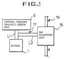
- FIG. 3 is a block diagram illustrating a battery's internal pressure measuring apparatus according to another embodiment of the present invention.
- This embodiment has the same construction as that of Figure 2 except for the provision of a gas collecting unit.
- the gas collecting unit which is denoted by the reference numeral 15, is connected between the battery 1 and the internal pressure measuring sensor unit 5 to sense the overcharged condition of the battery 1 as well as the battery's internal pressure.
- the gas collecting unit 15 is connected to a line L1, which connects the battery 1 and internal pressure measuring sensor unit 5 to each other, via a line L2 connected to the line L1.
- an intermediate valve 17 is installed for opening and closing the line L2 to selectively feed the gas in the battery 1 to the gas collecting unit 15.
- a gas supply valve 19 is provided at the gas collecting unit 15 to charge the gas collecting unit 15 with gas.
- the gas collecting unit 15 be charged with nitrogen or argon gas.
- the charge/discharge unit 3 When the charge/discharge unit 3 charges or discharges the battery 1, pressure is generated inside the battery 1.
- This internal pressure of the battery 1 is sensed by the internal pressure measuring sensor unit 5 which, in turn, generates an analog signal indicative of the sensed internal pressure.
- the analog signal from the internal pressure measuring sensor unit 5 is sent to the A/D convertor 9 which, in turn, converts the received signal into a digital signal.
- the computer 13 receives the digital signal from the A/D convertor 9 via the digital signal control unit 11.
- the computer 13 processes the received data so that the data is manageable using a database.
- the gas collecting unit 15 is charged with argon or nitrogen gas through the gas supply valve 19 while the intermediate valve 17 installed between the battery 1 and internal pressure measuring sensor unit 5 is closed.
- the gas supply valve 19 is closed.
- the intermediate valve 17 is then opened.
- gas generated in the battery 1 (consisting of oxygen gas generated at the anode and hydrogen gas generated at the cathode) enters the gas collecting unit 15 through the opened intermediate valve 17.
- the intermediate valve 17 is closed.
- the gas (oxygen and hydrogen gas) supplied from the battery 1 is mixed with the gas (argon or nitrogen gas) previously filled in the gas collecting unit 15. The mixture is then analyzed by a gas analyzing device to measure respective amounts of oxygen and hydrogen contained in the gas generated in the battery 1.
- the present invention provides an apparatus for measuring the internal pressure of a battery, capable of converting an analog signal output from its internal pressure measuring sensor into a digital signal being manageable in a database by a computer. Accordingly, the present invention provides an advantage of achieving easy data analysis and reduction.
- the measuring apparatus may also include a gas collecting unit for collecting and analyzing gas generated inside the battery while charging or discharging the battery. By the provision of the gas collecting unit, it is possible to easily check the portion of the battery (anode, cathode or electrolyte) where the gas is being generated in the overcharged condition of the battery, thereby immediately repairing the checked battery portion. Accordingly, the battery can have an improved performance.
Landscapes
- Engineering & Computer Science (AREA)
- Manufacturing & Machinery (AREA)
- Chemical & Material Sciences (AREA)
- Chemical Kinetics & Catalysis (AREA)
- Electrochemistry (AREA)
- General Chemical & Material Sciences (AREA)
- Physics & Mathematics (AREA)
- General Physics & Mathematics (AREA)
- Secondary Cells (AREA)
- Charge And Discharge Circuits For Batteries Or The Like (AREA)
Abstract
Description
- The present invention relates to an apparatus for measuring the internal pressure of a battery, and more particularly to a battery's internal pressure measuring apparatus being capable of measuring the pressure generated in the battery while charging or discharging the battery and of collecting and analyzing gas generated inside the battery while charging or discharging the battery.
- Figure 1 illustrates a conventional battery's internal pressure measuring apparatus. As shown in Figure 1, the measuring apparatus includes a charge/
discharge unit 3 for charging or discharging abattery 1, an internal pressuremeasuring sensor unit 5 for measuring the internal pressure of thebattery 1, and arecording unit 7 for recording a sensing signal generated from thesensor unit 5. In this measuring apparatus, the internal pressure measuringsensor unit 5 measures a pressure generated inside thebattery 1 while charging or discharging thebattery 1 through the charge/discharge unit 3. The battery's measured internal pressure is then recorded by therecording unit 7. However, data obtained by such a recording system can not be managed using a database. Furthermore, it is troublesome to reduce, compare and analyze such data. Such data work also requires a lot of time. - Therefore, it is an aim of preferred embodiments of the invention to solve or alleviate the above-mentioned problems and to provide an apparatus for measuring the internal pressure of a battery, being capable of converting an analog signal output from its internal pressure measuring sensor into a digital signal being manageable in a database by a computer to achieve easy data storage, analysis and reduction, and of collecting an analyzing gas generated inside the battery while charging or discharging the battery to easily check the portion of battery (anode, cathode and electrolyte) where the gas is generated in the overcharged condition of the battery, thereby immediately repairing the checked battery portion.
- According to a first aspect of the present invention, there is provided an apparatus for measuring the internal pressure of a battery, comprising: a charge/discharge unit for charging or discharging the battery; an internal pressure measuring sensor unit, for measuring the internal pressure of the battery while charging or discharging the battery through the charge/discharge unit; an analog/digital converting unit for converting a sensing signal output from the internal pressure measuring sensor unit into a digital signal; a digital signal control unit for controlling the digital signal output from the A/D converting unit so that the digital signal can be applied to a computer; and the computer for recording an output signal from the digital signal control unit using a database.
- Preferably, the apparatus further comprises: an intermediate valve installed between the battery and the internal pressure measuring sensor unit; and a gas collecting unit connected to the intermediate valve and adapted to sense an overcharged condition of the battery as well as the internal pressure of the battery.
- The gas collecting unit may be charged with argon or nitrogen gas.
- According to a second aspect of the invention, there is provided an apparatus for measuring the internal pressure of a battery while charging/discharging, the apparatus comprising: an internal pressure measuring sensor for measuring the internal pressure of the battery while charging or discharging; an analog/digital converting unit for converting a sensing signal output from the internal pressure measuring senor into a digital signal; and a digital signal control unit for controlling the digital signal output from the analog/digital converting unit so that the digital signal can be output to a computer.
- The apparatus may further comprise any feature or combination of features from the accompanying claims, description or abstract.
- For a better understanding of the invention, and to show how embodiments of the same may be carried into effect, reference will now be made, by way of example, to the accompanying diagrammatic drawings, in which:
- Figure 1 is a block diagram illustrating a conventional battery's internal pressure measuring apparatus;
- Figure 2 is a block diagram illustrating a battery's internal pressure measuring apparatus according to an embodiment of the present invention; and
- Figure 3 is a block diagram illustrating a battery's internal pressure measuring apparatus according to another embodiment of the present invention.
- Figure 2 is a block diagram illustrating a battery's internal pressure measuring apparatus according to an embodiment of the present invention. In Figure 2, elements respectively corresponding to those in Figure 1 are denoted by the same reference numerals. As shown in Figure 2, the apparatus includes a charge/
discharge unit 3 for charging or discharging abattery 1 and an internal pressure measuringsensor unit 5 for measuring the internal pressure of thebattery 1. The apparatus also includes an analog/digital (A/D) convertingunit 9 coupled to the internal pressuremeasuring sensor unit 5. The A/D converting unit 9 serves to convert a sensing signal output from the internal pressure measuringsensor unit 5 into a digital signal capable of being read by a computer. Coupled to the A/D converting unit 9 is a digitalsignal control unit 11 for controlling the digital signal output from the A/D converting unit 9 so that the digital signal can be applied to acomputer 13. Thecomputer 13, which is coupled to the digitalsignal control unit 11, may be a personal computer which is suitable to record an output signal from the digitalsignal controlling unit 11 using a database. - Figure 3 is a block diagram illustrating a battery's internal pressure measuring apparatus according to another embodiment of the present invention. This embodiment has the same construction as that of Figure 2 except for the provision of a gas collecting unit. As shown in Figure 3, the gas collecting unit, which is denoted by the
reference numeral 15, is connected between thebattery 1 and the internal pressure measuringsensor unit 5 to sense the overcharged condition of thebattery 1 as well as the battery's internal pressure. In particular, thegas collecting unit 15 is connected to a line L1, which connects thebattery 1 and internal pressure measuringsensor unit 5 to each other, via a line L2 connected to the line L1. On the line L2, anintermediate valve 17 is installed for opening and closing the line L2 to selectively feed the gas in thebattery 1 to thegas collecting unit 15. Agas supply valve 19 is provided at thegas collecting unit 15 to charge thegas collecting unit 15 with gas. - It is preferred that the
gas collecting unit 15 be charged with nitrogen or argon gas. - The operation of the battery's internal pressure measuring apparatus will now be described in conjunction with the embodiment of Figure 3.
- When the charge/
discharge unit 3 charges or discharges thebattery 1, pressure is generated inside thebattery 1. This internal pressure of thebattery 1 is sensed by the internal pressure measuringsensor unit 5 which, in turn, generates an analog signal indicative of the sensed internal pressure. The analog signal from the internal pressuremeasuring sensor unit 5 is sent to the A/D convertor 9 which, in turn, converts the received signal into a digital signal. Thecomputer 13 receives the digital signal from the A/D convertor 9 via the digitalsignal control unit 11. Thecomputer 13 processes the received data so that the data is manageable using a database. - Meanwhile, the
gas collecting unit 15 is charged with argon or nitrogen gas through thegas supply valve 19 while theintermediate valve 17 installed between thebattery 1 and internal pressuremeasuring sensor unit 5 is closed. After charging thegas collecting unit 15 with the argon or nitrogen gas, thegas supply valve 19 is closed. Theintermediate valve 17 is then opened. As a result, gas generated in the battery 1 (consisting of oxygen gas generated at the anode and hydrogen gas generated at the cathode) enters thegas collecting unit 15 through the openedintermediate valve 17. Thereafter, theintermediate valve 17 is closed. In thegas collecting unit 15, the gas (oxygen and hydrogen gas) supplied from thebattery 1 is mixed with the gas (argon or nitrogen gas) previously filled in thegas collecting unit 15. The mixture is then analyzed by a gas analyzing device to measure respective amounts of oxygen and hydrogen contained in the gas generated in thebattery 1. - As apparent from the above description, embodiments of the present invention provide an apparatus for measuring the internal pressure of a battery, capable of converting an analog signal output from its internal pressure measuring sensor into a digital signal being manageable in a database by a computer. Accordingly, the present invention provides an advantage of achieving easy data analysis and reduction. In accordance with the present invention, the measuring apparatus may also include a gas collecting unit for collecting and analyzing gas generated inside the battery while charging or discharging the battery. By the provision of the gas collecting unit, it is possible to easily check the portion of the battery (anode, cathode or electrolyte) where the gas is being generated in the overcharged condition of the battery, thereby immediately repairing the checked battery portion. Accordingly, the battery can have an improved performance.
- Although the preferred embodiments of the invention have been disclosed for illustrative purposes, those skilled in the art will appreciate that various modifications, additions and substitutions are possible, without departing from the scope and spirit of the invention as disclosed in the accompanying claims.
- The reader's attention is directed to all papers and documents which are filed concurrently with or previous to this specification in connection with this application and which are open to public inspection with this specification, and the contents of all such papers and documents are incorporated herein by reference.
- All of the features disclosed in this specification (including any accompanying claims, abstract and drawings), and/or all of the steps of any method or process so disclosed, may be combined in any combination, except combinations where at least some of such features and/or steps are mutually exclusive.
- Each feature disclosed in this specification (including any accompanying claims, abstract and drawings), may be replaced by alternative features serving the same, equivalent or similar purpose, unless expressly stated otherwise. Thus, unless expressly stated otherwise, each feature disclosed is one example only of a generic series of equivalent or similar features.
- The invention is not restricted to the details of the foregoing embodiment(s). The invention extends to any novel one, or any novel combination, of the features disclosed in this specification (including any accompanying claims, abstract and drawings), or to any novel one, or any novel combination, of the steps of any method or process so disclosed.
Claims (5)
- An apparatus for measuring the internal pressure of a battery, comprising:
a charge/discharge unit (3) for charging or discharging the battery;
an internal pressure measuring sensor unit (5) for measuring the internal pressure of the battery (1) while charging or discharging the battery through the charge/discharge unit;
an analog/digital converting unit (9) for converting a sensing signal output from the internal pressure measuring sensor unit (5) into a digital signal;
a digital signal control unit (11) for controlling the digital signal output from the A/D converting unit (9) so that the digital signal can be applied to a computer (13); and
the computer (13) for recording an output signal from the digital signal control unit (11) using a database. - The apparatus in accordance with claim 1, further comprising:
an intermediate valve installed (17) between the battery (1) and the internal pressure measuring sensor unit (5); and
a gas collecting unit (15) connected to the intermediate valve (17) and adapted to sense an overcharged condition of the battery (1) as well as the internal pressure of the battery (1). - The apparatus in accordance with claim 2, wherein the gas collecting unit (15) is charged with argon or nitrogen gas.
- An apparatus for measuring the internal pressure of a battery while charging/discharging, the apparatus comprising:
an internal pressure measuring sensor (5) for measuring the internal pressure of the battery (1) while charging or discharging;
an analog/digital converting unit (9) for converting a sensing signal output from the internal pressure measuring senor (5) into a digital signal; and
a digital signal control unit (11) for controlling the digital signal output from the analog/digital converting unit (9) so that the digital signal can be output to a computer (13). - Apparatus according to claim 4, further comprising any feature or combination of features from the accompanying claims, description or abstract.
Applications Claiming Priority (2)
| Application Number | Priority Date | Filing Date | Title |
|---|---|---|---|
| KR1019940038130A KR960024447A (en) | 1994-12-28 | 1994-12-28 | Battery withstand voltage measurement device |
| KR9438130 | 1994-12-28 |
Publications (2)
| Publication Number | Publication Date |
|---|---|
| EP0723145A2 true EP0723145A2 (en) | 1996-07-24 |
| EP0723145A3 EP0723145A3 (en) | 1996-08-07 |
Family
ID=19404425
Family Applications (1)
| Application Number | Title | Priority Date | Filing Date |
|---|---|---|---|
| EP95309268A Withdrawn EP0723145A3 (en) | 1994-12-28 | 1995-12-20 | Apparatus for measuring internal pressure of battery |
Country Status (5)
| Country | Link |
|---|---|
| US (1) | US5650711A (en) |
| EP (1) | EP0723145A3 (en) |
| JP (1) | JP2755929B2 (en) |
| KR (1) | KR960024447A (en) |
| CN (1) | CN1132350A (en) |
Cited By (2)
| Publication number | Priority date | Publication date | Assignee | Title |
|---|---|---|---|---|
| WO2002035638A1 (en) * | 2000-09-26 | 2002-05-02 | Einar Gotaas | Method for early detection of defective single cells in valve controlled batteries |
| WO2015018426A1 (en) * | 2013-08-09 | 2015-02-12 | Fraunhofer-Gesellschaft Zur Förderung Der Angewandten Forschung E .V. | Battery |
Families Citing this family (16)
| Publication number | Priority date | Publication date | Assignee | Title |
|---|---|---|---|---|
| JP3225192B2 (en) * | 1996-04-10 | 2001-11-05 | 本田技研工業株式会社 | Battery exhaust gas control system |
| KR100477734B1 (en) * | 1997-12-20 | 2005-06-07 | 삼성에스디아이 주식회사 | Charge / discharger of lithium ion battery |
| EP1164680B1 (en) * | 2000-04-28 | 2016-08-10 | Panasonic Corporation | Method for charging a battery pack including a plurality of battery units |
| US6608467B2 (en) | 2001-09-26 | 2003-08-19 | Ford Global Technologies, Llc | Replacement battery formation system |
| CN100442590C (en) * | 2004-07-19 | 2008-12-10 | 肇庆市风华锂电池有限公司 | Method for measuring gas production rate of battery formation and system therefor |
| KR100889244B1 (en) * | 2005-04-20 | 2009-03-17 | 주식회사 엘지화학 | Secondary Battery Module with Piezoelectric Sensor |
| CN100440605C (en) * | 2006-12-14 | 2008-12-03 | 天津力神电池股份有限公司 | Lithium ion cell internal pressure measuring method |
| KR101029518B1 (en) * | 2009-02-02 | 2011-04-25 | 전남대학교산학협력단 | Withstand voltage measurement device for secondary battery |
| US20110202194A1 (en) * | 2010-02-15 | 2011-08-18 | General Electric Company | Sub-metering hardware for measuring energy data of an energy consuming device |
| EP2817840B1 (en) | 2012-02-23 | 2018-12-26 | The City University Of New York | Management of gas pressure and electrode state of charge in alkaline batteries |
| CN102680191B (en) * | 2012-06-07 | 2015-06-10 | 北京有色金属研究总院 | Leakage detection device for power cells |
| KR101989909B1 (en) | 2015-10-06 | 2019-06-17 | 주식회사 엘지화학 | A device for collecting inner gas in secondary battery and charging/discharging in secondary battery |
| CN107449543B (en) * | 2016-06-01 | 2020-12-22 | 宁德时代新能源科技股份有限公司 | Hard shell secondary battery internal pressure detection device |
| JP6409940B2 (en) * | 2017-10-31 | 2018-10-24 | 住友金属鉱山株式会社 | Evaluating gas generated from non-aqueous electrolyte secondary batteries |
| DE102018204220A1 (en) | 2018-03-20 | 2019-09-26 | Volkswagen Aktiengesellschaft | battery |
| CN111537126B (en) * | 2020-04-28 | 2022-12-13 | 苏州清陶新能源科技有限公司 | Tool for determining pretightening force of soft package battery, method for determining pretightening force of soft package battery and method for assembling module |
Family Cites Families (17)
| Publication number | Priority date | Publication date | Assignee | Title |
|---|---|---|---|---|
| CH576878A5 (en) * | 1973-10-08 | 1976-06-30 | Varta Batterie | |
| US4282476A (en) * | 1979-03-16 | 1981-08-04 | Frezzolini Electronics, Inc. | Variable pressure control switch for battery charging circuit |
| US4327157A (en) * | 1981-02-20 | 1982-04-27 | The United States Of America As Represented By The Secretary Of The Navy | Stabilized nickel-zinc battery |
| US4499424A (en) * | 1982-04-09 | 1985-02-12 | The United States Of America As Represented By The Administrator Of The National Aeronautics And Space Administration | State-of-charge coulometer |
| US4689544A (en) * | 1985-10-17 | 1987-08-25 | Hughes Aircraft Company | Control of the charging of pressurized gas-metal electrical storage cells |
| US5346781A (en) * | 1989-02-23 | 1994-09-13 | Matsushita Electric Industrial Co., Ltd. | Alkaline storage battery |
| US5313061A (en) * | 1989-06-06 | 1994-05-17 | Viking Instrument | Miniaturized mass spectrometer system |
| JP2559635B2 (en) * | 1989-12-28 | 1996-12-04 | 日本電池株式会社 | Method of charging storage battery provided with electrolyte stirring device |
| JP3021545B2 (en) * | 1990-05-21 | 2000-03-15 | 松下電器産業株式会社 | Battery tightness inspection device |
| JPH0479732A (en) * | 1990-07-20 | 1992-03-13 | Hitachi Koki Co Ltd | Boosting charger |
| US5396163A (en) * | 1991-03-13 | 1995-03-07 | Inco Limited | Battery charger |
| EP0560535B1 (en) * | 1992-03-05 | 1999-11-03 | Sanyo Electric Co., Limited. | Hydrogen-absorbing alloy for negative electrode |
| CA2097363A1 (en) * | 1992-06-03 | 1993-12-04 | Hideo Ueda | Expired air examination device and method for clinical purpose |
| US5327784A (en) * | 1992-07-09 | 1994-07-12 | Ovonic Battery Company, Inc. | Apparatus for measuring the pressure inside a rechargeable electrochemical cell |
| JP3027884B2 (en) * | 1992-08-28 | 2000-04-04 | 松下電器産業株式会社 | Battery airtightness inspection method |
| JPH0676861A (en) * | 1992-08-31 | 1994-03-18 | Shinko Electric Co Ltd | Battery charging device for unmanned conveying vehicle |
| US5529857A (en) * | 1993-10-06 | 1996-06-25 | Sanyo Electric Co., Ltd. | Hydrogen-absorbing alloy electrode and process for producing the same |
-
1994
- 1994-12-28 KR KR1019940038130A patent/KR960024447A/en not_active Withdrawn
-
1995
- 1995-11-10 JP JP7292888A patent/JP2755929B2/en not_active Expired - Lifetime
- 1995-11-21 CN CN95119753A patent/CN1132350A/en active Pending
- 1995-12-20 EP EP95309268A patent/EP0723145A3/en not_active Withdrawn
- 1995-12-21 US US08/576,355 patent/US5650711A/en not_active Expired - Fee Related
Cited By (2)
| Publication number | Priority date | Publication date | Assignee | Title |
|---|---|---|---|---|
| WO2002035638A1 (en) * | 2000-09-26 | 2002-05-02 | Einar Gotaas | Method for early detection of defective single cells in valve controlled batteries |
| WO2015018426A1 (en) * | 2013-08-09 | 2015-02-12 | Fraunhofer-Gesellschaft Zur Förderung Der Angewandten Forschung E .V. | Battery |
Also Published As
| Publication number | Publication date |
|---|---|
| US5650711A (en) | 1997-07-22 |
| KR960024447A (en) | 1996-07-20 |
| JP2755929B2 (en) | 1998-05-25 |
| CN1132350A (en) | 1996-10-02 |
| EP0723145A3 (en) | 1996-08-07 |
| JPH09115556A (en) | 1997-05-02 |
Similar Documents
| Publication | Publication Date | Title |
|---|---|---|
| EP0723145A2 (en) | Apparatus for measuring internal pressure of battery | |
| Pop et al. | State-of-the-art of battery state-of-charge determination | |
| EP1611449B1 (en) | System and method for measuring fuel cell voltage and high frequency resistance | |
| CN109073713A (en) | The equipment, system and method for the internal driving of test battery are measured for frequency of use response | |
| PT1038291E (en) | Apparatus and methods for detecting emotions | |
| US11543351B2 (en) | All-in-one handheld machine for testing drugs in hairs | |
| EP0813313A3 (en) | Mobile communication receiving apparatus | |
| US5672973A (en) | Apparatus for monitoring battery residual capacity in mulitple modes | |
| EP1489431A3 (en) | Apparatus and method for detecting residual energy of a battery | |
| DK0769458T3 (en) | Method and apparatus for recording collection volumes, especially of household waste | |
| CN107063583A (en) | The acoustic emission detection system and method for a kind of valve leak | |
| US5311764A (en) | Rebound hammer | |
| JPH02502230A (en) | Magnetic character reading device and method | |
| EP1528377A3 (en) | Diagnostic vibration data collector and analyzer | |
| CN1090044A (en) | Portable integrated dynamic test-pile analyzing instrument | |
| CN109819035A (en) | Wisdom building site management system | |
| US7126121B1 (en) | Real-time video radiation exposure monitoring system | |
| CN112526441A (en) | Multifunctional integrated direct current electric energy calibrating device | |
| JPH08145728A (en) | Signal waveform recording device | |
| Jeffery et al. | A search for variability in the helium-rich subdwarf HD 144941 | |
| JPH0746468A (en) | Monitor device | |
| JP3395448B2 (en) | Material testing machine | |
| Post et al. | Estimating Residual Fatigue Life of Bridges | |
| SU957048A1 (en) | Device for determination of modulus of elasticity of a material having non-linear elastoplastic properties | |
| CN116413617A (en) | Test method of battery test system |
Legal Events
| Date | Code | Title | Description |
|---|---|---|---|
| PUAI | Public reference made under article 153(3) epc to a published international application that has entered the european phase |
Free format text: ORIGINAL CODE: 0009012 |
|
| PUAL | Search report despatched |
Free format text: ORIGINAL CODE: 0009013 |
|
| 17P | Request for examination filed |
Effective date: 19960105 |
|
| AK | Designated contracting states |
Kind code of ref document: A2 Designated state(s): DE GB NL |
|
| AK | Designated contracting states |
Kind code of ref document: A3 Designated state(s): DE GB NL |
|
| 17Q | First examination report despatched |
Effective date: 19981001 |
|
| STAA | Information on the status of an ep patent application or granted ep patent |
Free format text: STATUS: THE APPLICATION IS DEEMED TO BE WITHDRAWN |
|
| 18D | Application deemed to be withdrawn |
Effective date: 19990413 |