EP0723066A2 - Bohrmeissel mit verbesserter Schneidstruktur - Google Patents
Bohrmeissel mit verbesserter Schneidstruktur Download PDFInfo
- Publication number
- EP0723066A2 EP0723066A2 EP96100576A EP96100576A EP0723066A2 EP 0723066 A2 EP0723066 A2 EP 0723066A2 EP 96100576 A EP96100576 A EP 96100576A EP 96100576 A EP96100576 A EP 96100576A EP 0723066 A2 EP0723066 A2 EP 0723066A2
- Authority
- EP
- European Patent Office
- Prior art keywords
- cutter
- cutting element
- earth
- gage
- chisel
- Prior art date
- Legal status (The legal status is an assumption and is not a legal conclusion. Google has not performed a legal analysis and makes no representation as to the accuracy of the status listed.)
- Granted
Links
Images


Classifications
-
- E—FIXED CONSTRUCTIONS
- E21—EARTH OR ROCK DRILLING; MINING
- E21B—EARTH OR ROCK DRILLING; OBTAINING OIL, GAS, WATER, SOLUBLE OR MELTABLE MATERIALS OR A SLURRY OF MINERALS FROM WELLS
- E21B17/00—Drilling rods or pipes; Flexible drill strings; Kellies; Drill collars; Sucker rods; Cables; Casings; Tubings
- E21B17/10—Wear protectors; Centralising devices, e.g. stabilisers
- E21B17/1092—Gauge section of drill bits
-
- E—FIXED CONSTRUCTIONS
- E21—EARTH OR ROCK DRILLING; MINING
- E21B—EARTH OR ROCK DRILLING; OBTAINING OIL, GAS, WATER, SOLUBLE OR MELTABLE MATERIALS OR A SLURRY OF MINERALS FROM WELLS
- E21B10/00—Drill bits
- E21B10/08—Roller bits
- E21B10/16—Roller bits characterised by tooth form or arrangement
-
- E—FIXED CONSTRUCTIONS
- E21—EARTH OR ROCK DRILLING; MINING
- E21B—EARTH OR ROCK DRILLING; OBTAINING OIL, GAS, WATER, SOLUBLE OR MELTABLE MATERIALS OR A SLURRY OF MINERALS FROM WELLS
- E21B10/00—Drill bits
- E21B10/46—Drill bits characterised by wear resisting parts, e.g. diamond inserts
- E21B10/50—Drill bits characterised by wear resisting parts, e.g. diamond inserts the bit being of roller type
- E21B10/52—Drill bits characterised by wear resisting parts, e.g. diamond inserts the bit being of roller type with chisel- or button-type inserts
Definitions
- the present invention generally relates to earth-boring drill bits. More particularly, the present invention relates to improved cutting structures or geometries for earth-boring drill bits.
- the cuttings from the bottom and sides of the borehole are washed away by drilling fluid that is pumped down from the surface through the hollow rotating drillstring, and are carried in suspension in the drilling fluid to the surface.
- the form and location of the teeth or inserts upon the cutters have been found to be extremely important to the successful operation of the bit. Certain aspects of the design of the cutters becomes particularly important if the bit is to penetrate deep into a formation to effectively strain and induce failure in the formation material.
- rock ribs In hard, high compressive strength, tough, and abrasive formation materials, such as limestones, dolomites and sandstones, the formation of rock ribs can affect bit performance seriously, because the rock ribs are not destroyed easily by conventional cutter action due to their inherent toughness and high strength. Because of the strength of these materials, tooth or insert penetration is reduced, and the rock ribs are not as easily disintegrated as in the softer formation materials. Rock ribs formed in high compressive strength, abrasive formation materials can become quite large, causing the cutter to ride up on the ribs and robbing the teeth or inserts of the unit load necessary to accomplish effective penetration and crushing of formation material.
- cutters with more closely spaced teeth or inserts reduces the size of rock ribs in hard, tough, and abrasive formations, but leads to balling, or clogging of cutting structure, in the softer formation materials. Furthermore, the presence of a multiplicity of closely spaced teeth or inserts reduces the unit load on each individual tooth and slows the rate of penetration of the softer formations.
- U.S. Patent No. 2,804,242, August 27, 1957, to Spengler discloses gage shaving teeth alternately positioned between heel teeth, the shaving teeth having outer shaving surfaces in the same plane as the outer edges of the heel teeth to shave the sidewall of the borehole during drilling operation.
- the shaving teeth are preferably one-half the height of the heel teeth, and thus function essentially as part of the primary heel cutting structure. In the rounded condition, the shaving teeth conform to the corner of the borehole, reducing the unit load on the heel teeth and their ability to penetrate and disintegrate formation material.
- the shaving teeth disclosed by Spengler are generally fragile and thus subject to accelerated wear and rapid rounding, exerting the undesirable increased lateral forces on the cutter discussed above.
- a principal object of the present invention is to provide an earth-boring bit having an improved ability to maintain an efficient cutting geometry or structure as the earth-boring bit alternately encounters hard and soft formation materials and as the bit wears during drilling operation in borehole.
- an earth-boring bit having a bit body and at least one cutter rotatably secured to the bit body.
- the cutter has a cutter shell surface including a gage surface and a heel surface.
- a plurality of cutting elements inserts are arranged in generally circumferential rows on the cutter.
- At least one chisel-shaped cutting element is secured to the gage surface.
- the chisel-shaped cutting element has a pair of surfaces converging to define a circumferential crest and is tilted toward the heel surface such that a line drawn through the center of the cutting element and its crest defines an acute angle of between about 15 and 75 degrees with the gage surface of the cutter.
- the chisel-shaped cutting element has a generally cylindrical base interference fit in an aperture in the gage surface and a counterbore is formed in the gage surface and generally surrounds the chisel-shaped element.
- At least one scraper cutting element is secured to a generally circular juncture between the gage and heel surfaces of the cutter.
- the scraper cutting element has a pair of surfaces converging to define a crest in general alignment with the juncture between the gage and heel surfaces.
- one of the surfaces of the chisel-shaped cutting element is formed of a more wear-resistant material than the other surface, wherein the chisel-shaped cutting element is self-sharpening.
- an outermost surface of the chisel-shaped insert is generally aligned with and projects beyond the gage surface.
- the outermost surface is relieved between about three and 15 degrees from the borehole wall.
- first and second rows of chisel-shaped cutting elements are provided, the second row being nearer the cutter backface, providing a staggered, dual row of chisel-shaped cutting elements.
- the cutting elements on the inner rows of the cutters may be hard metal inserts interference fit in apertures in the cutter or milled teeth formed from the material of the cutter.
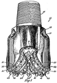
- Figure 1 is a perspective view of an earth-boring bit according to the present invention.
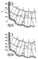
- Figures 2A through 2C are fragmentary, longitudinal section views showing progressive wear of a prior-art earth-boring bit.
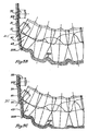
- Figures 3A through 3C are fragmentary, longitudinal section views of the progressive wear of an earth-boring bit according to the present invention.
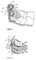
- Figure 4 is an enlarged view of a scraper cutting element in contact with the sidewall of the borehole.
- Figures 5A and 5B are plan and side elevation views, respectively, of the preferred scraper cutting element of Figure 4.
- Figure 6 is a fragmentary section view of a portion of the earth-boring bit according to the present invention in operation in a borehole.
- Figure 7 is a perspective view of an earth-boring bit according to the present invention.
- Figure 8 is a fragmentary section view of the earth-boring bit of Figure 7, depicting the relationship of the cutting elements of the cutters of the bit on the bottom of the borehole.
- Figure 9 is a fragmentary section view of an earth-boring bit according to the present invention embodying a variation of the invention illustrated in Figures 7 and 8.
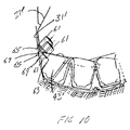
- Figure 10 is a fragmentary section view of a milled- or steel-tooth bit according to the preferred embodiment of the present invention.
- Bit 11 includes a bit body 13 , which is threaded at its upper extent 15 for connection into a drillstring.
- Each leg of bit 11 is provided with a lubricant compensator 17 , a preferred embodiment of which is disclosed in U.S. Patent No. 4,276,946, July 7, 1981, to Millsapps.
- At least one nozzle 19 is provided in bit body 13 to spray drilling fluid from within the drillstring to cool and lubricate bit 11 during drilling operation.
- Three cutters 21, 23, 25 are rotatably secured to each leg of bit body 13 .
- Each cutter 21, 23, 25 has a cutter shell surface including a gage surface 31 and a heel surface 41 .
- a plurality of cutting elements in the form of hard metal inserts, are arranged in generally circumferential rows on each cutter.
- Each cutter 21, 23, 25 has a gage surface 31 with a row of gage inserts 33 thereon.
- a heel surface 41 intersects each gage surface 31 and has at least one row of heel cutting elements 43 thereon.
- At least one scraper insert 51 is secured to the cutter shell surface at the intersection of or generally circular juncture between gage and heel surfaces 31, 41 and generally intermediate a pair of heel cutting elements 43.
- a scraper cutting element 51 is located between each heel cutting element 43 , in an alternating arrangement.
- scraper insert 51 comprises a generally cylindrical body 53 , which is adapted to be received in an aperture in the cutter shell surface at the intersection of gage and heel surfaces 31, 41 .
- scraper insert 51 is secured within the aperture by an interference fit.
- Extending upwardly from generally cylindrical body 53 are a pair of insert surfaces 55, 57 , which converge to define a cutting edge 59 .
- cutting edge 59 is oriented circumferentially, i.e., normal to the axis of rotation of each cutter 21, 23, 25.
- scraper cutting element is secured to the cutter shell surface such that one of scraper surfaces 55, 57 defines a gage insert surface that extends generally parallel to the sidewall ( 205 in Fig. 3A) of the borehole. Another of scraper insert surfaces 55, 57 defines a heel insert surface.
- scraper cutting element 51 is oriented such that gage scraper surface 57 is generally aligned with and projects beyond gage surface 31 . It is contemplated that surface 57 may be relieved away from the sidewall of the borehole a clearance angle ⁇ between three and 15 degrees. Relieving surface 57 decreases engagement between scraper cutting element 51 and the sidewall of the borehole, which may reduce the ability of scraper 51 to protect gage surface 31 against abrasive wear. However, it is believed that the reduction in frictional engagement between scraper 51 and the sidewall more than compensates for the reduction in abrasion resistance.
- Figures 2A - 2B are fragmentary, longitudinal section views of the cutting geometry of a prior-art earth-boring bit, showing progressive wear from a new condition to the "rounded gage" condition.
- the reference numerals in Figures 2A - 2C that begin with the numeral 1 point out structure that is analogous to that illustrated in earth-boring bit 11 according to the present invention depicted in Figure 1, e.g., heel tooth or cutting element 143 in Figure 2A is analogous to heel cutting element 43 depicted in Figure 1, heel surface 141 in Figure 2A is analogous to heel surface 41 depicted in Figure 1, etc.
- Figure 2A depicts a prior-art earth-boring bit in a borehole.
- Figure 2A depicts the prior-art earth-boring bit in a new or unworn condition, in which the intersection between gage and heel surfaces 131, 141 is prominent and does not contact sidewall 205 of borehole.
- the majority of the teeth or cutting elements engage the bottom 201 of the borehole.
- Heel teeth or inserts 143 engage corner 203 of the borehole, which is generally defined at the intersection of sidewall 205 and bottom 201 of borehole.
- Gage insert 133 does not yet engage sidewall 205 of the borehole to trim the sidewall and maintain the minimum gage diameter of the borehole.
- Figure 2B depicts the prior-art earth-boring bit of Figure 2A in a moderately worn condition.
- the outer end of heel tooth or insert 143 is abrasively worn, as is the intersection of gage and heel surfaces 131, 141.
- Abrasive erosion of heel tooth or insert 143 and gage and heel surfaces 131, 141 of cutter shell causes the earth-boring bit to conform with corner 203 and sidewall 205 of the borehole.
- gage insert 133 cuts into sidewall 205 of the borehole to maintain gage diameter in the absence of heel inserts' 143 ability to do so.
- Sidewall of borehole 205 is in constant conforming contact with the cutter shell surface, generally at what remains of the intersection between gage and heel surfaces 131, 141 .
- Figure 2C illustrates the prior-art earth-boring bit of Figures 2A and 2B in a severely worn, or rounded gage, condition.
- this rounded gage condition the outer end of heel tooth or insert 143 is severely worn, as is the cutter shell surface generally in the area of the intersection of gage and heel surfaces 131, 141.
- gage insert 133 excessively penetrates sidewall 205 of the borehole and bears the bulk of the burden in maintaining gage, a condition for which gage insert 133 is not optimally designed, thus resulting in inefficient gage cutting and lower rates of penetration.
- Figures 3A - 3C are fragmentary, longitudinal section views of earth-boring bit 11 according to the present invention as it progressively wears in a borehole.
- Figure 3A illustrates earth-boring bit 11 in a new or unworn condition, wherein the majority of the teeth or inserts engage bottom 201 of the borehole. Heel inserts or teeth 43 engage corner 203 of the borehole.
- one of scraper insert surface 57 defines a gage insert surface 57 that extends generally parallel to sidewall 205 of the borehole.
- Another of scraper insert surfaces 55, 57 defines a heel insert surface 55 that defines a negative rake angle ⁇ with respect to sidewall 205 of the borehole.
- Scraper insert 51 is constructed of a material having greater wear-resistance than at least gage and heel surfaces 31, 41 of the cutter shell surface.
- the gage insert surface of scraper insert 51 protects gage surface 31 from severe abrasive erosion resulting from contact with sidewall 205 of the borehole.
- the heel insert surface of scraper insert 51 protects heel surface 41 from abrasive erosion resulting from contact with corner 203 of the borehole.
- Scraper insert 51 also inhibits formation of rock ribs between adjacent heel cutting elements 43.
- Cutting edge 59 creates a secondary corner 207 and kerfs nascent rock ribs, disintegrating them before they can detract from efficient drilling.
- Figure 3B depicts earth-boring bit 11 in a moderately worn condition in which the outer end of heel tooth or insert 43 is worn.
- scraper insert 51 has prevented a great deal of the cutter shell erosion at the intersection of gage and heel surfaces 31, 41 , and still functions to form a the secondary corner, thereby maintaining a clearance between gage insert 33 and sidewall 205 of the borehole, and avoiding conformity.
- the presence of scraper insert 51 promotes cutting efficiency and deters rapid abrasive erosion of the cutter shell surface.
- Figure 3C illustrates earth-boring bit 11 according to the present invention in a severely worn condition in which the outer end of heel tooth or insert 43 is severely worn and the cutter shell surface is only moderately eroded.
- FIGS 5A and 5B are an enlarged elevation and plan views of a preferred scraper insert 51 according to the present invention.
- Scraper insert 51 is formed of a hard metal such as cemented tungsten carbide or similar material having high hardness and abrasion-resistance.
- one of scraper insert surfaces 55, 57 will define a gage insert surface
- the other of scraper insert surfaces 55, 57 will define a heel insert surface.
- the gage insert and heel insert surfaces 55, 57 converge at a right angle to define a circumferentially oriented cutting edge 59 for engagement with sidewall 205 of the borehole.
- the radius or width of cutting edge 59 is less than or equal to the depth of penetration of cutting edge 59 into formation material of the borehole as bit 11 wears or rock ribs form.
- scraper insert 51 requires maintenance of a sharp cutting edge 59 .
- one of scraper insert surfaces 55, 57 preferably is formed of a more wear-resistant material than the other of surfaces 55, 57 .
- the differential rates of wear of surfaces 55, 57 results in a self-sharpening scraper insert 51 that is capable of maintaining a sharp cutting edge 59 over the drilling life of earth-boring bit 11 .
- the more wear-resistant of scraper insert surfaces 55, 57 may be formed of a different grade or composition of hard metal than the other, or could be formed of an entirely different material such as polycrystalline diamond or the like, the remainder of the insert being a conventional hard metal.
- scraper insert 51 should be formed of a material having a greater wear-resistance than the material of the cutter shell surface, which is usually steel, so that scraper insert 51 can effectively prevent erosion of the cutter shell surface at the intersection of gage and heel surfaces 31, 41.
- scraper insert 51 serves as a secondary cutting structure.
- the cutting structure is described as "secondary" to distinguish it from primary cutting structure such as heel inserts 43, which have the primary function of penetrating formation material to crush and disintegrate the material as cutters 21, 23, 25 roll and slide over the bottom of the borehole.
- bits 11 having widely spaced teeth are designed to achieve high rates of penetration in soft, low compressive strength formation materials such as shale.
- Such a bit 11 is expected to encounter hard, tough, and abrasive streaks of formation material such as limestones, dolomites, or sandstones.
- Addition of primary cutting structure like heel inserts 43 or the inner row inserts, assists in penetration of these hard, abrasive materials and helps prevent cutter shell erosion. But, this additional primary cutting structure reduces the unit load on each tooth or insert, drastically reducing the rate of penetration of bit 11 through the soft material it is designed to drill.
- scraper insert 51 functions only as secondary cutting structure, engaging formation material only when heel inserts 43 are worn, or when large rock ribs form while drilling a hard, abrasive interval, the amount of projection of cutting edge 59 from heel surface 41 must be kept within certain limits. Clearly, to avoid becoming primary structure, cutting edge 59 must not project beyond heel surface 41 more than one-half the projection of heel insert 43. Further, to insure that scraper insert 51 engages formation material only when large rock ribs form, the projection of cutting edge 59 must be less than 30% of the pitch between the pair of heel teeth that scraper insert 51 is secured between.
- Pitch describes the distance or spacing between two teeth in the same row of an earth-boring bit. Pitch, in this case, is measured as the center-to-center linear distance between the crests of any two adjacent teeth in the same row.
- FIG. 6 depicts a fragmentary view of a portion of an earth-boring bit 11 according to the present invention operating in a borehole.
- Figure 6 illustrates the manner in which heel inserts 43 penetrate and disintegrate formation material 301 .
- Heel teeth 43 make a series of impressions 303, 305, 307 in formation material 301 .
- Buildups 309, 311 are expected in most drilling, but in drilling hard, abrasive formations with bits having large-pitch, or widely spaced, heel inserts 43 , these buildups can become large enough to detract from bit performance by engaging the cutter shell surface and reducing the unit load on each heel insert 43.
- Projection P of heel inserts 43 from heel surface provides a datum plane for reference purposes because it naturally governs the maximum penetration distance of heel inserts 43 .
- Buildup height BH is measured relative to each impression 303, 305, 307 as the distance from the upper surface of the buildup to the bottom of each impression 303, 305, 307 .
- cutter shell clearance C is the distance between the heel surface 41 and the upper surface of the buildup of interest. As stated above, it is most advantageous that clearance C be greater than zero in hard, tough, and abrasive formations. It has been determined that buildup height BH is a function of pitch and generally does not exceed approximately 30% of the pitch of heel inserts 43 , at which point clearance C is zero and as a reduction in unit load on heel inserts 43 and cutter erosion occur.
- scraper insert 51 should not engage formation material until buildup 309 begins to enlarge into a rock rib or the depth of cut approaches projection P of heel inserts 43 , wherein clearance C approaches zero. This is accomplished by limiting the projection of cutting edge 59 from heel surface 41 to an amount less than 30% of the pitch of the pair of heel inserts 43 between which scraper insert 51 is secured.
- scraper inserts 51 have a projection of 0.188 inch, which is less than one-half (0.305 inch) projection P of heel inserts 43 and 30% of pitch, which is 0.60 inch.
- FIG 7 is a perspective view of an earth-boring bit 11 according to the preferred embodiment of the present invention.
- Bit 11 is generally similar to that described in connection with Figure 1 , but with the addition of a row of chisel-shaped cutting elements 61 secured to gage surface 31 of each cutter 21, 23, 25.
- each chisel-shaped cutting element 61 is formed similarly to scraper insert 51 described above, but is positioned on gage surface 31 , rather than at the intersection or generally circular juncture of gage 31 and heel 41 surfaces.
- chisel-shaped cutting elements 61 alternate with scraper cutting elements 51 to provide staggered rows of secondary and tertiary cutting structure.
- each chisel-shaped cutting element 61 is surrounded by a generally circular counterbore 63, which serves to provide an area around cutting element 61 that facilitates movement of cuttings and abrasive fines around cutting element 61 and up the borehole.
- chisel-shaped cutting elements 61 are tilted toward heel surface 41 such that they are oriented in the direction of cut or advance of each cutter 21, 23, 25 as it rolls and slides on the bottom of the borehole.
- Figure 8 is a fragmentary section view of earth-boring bit 11 of Figure 7 illustrating the superimposition of the various cutting elements on cutters relative to one another and to the bottom of the borehole.
- Inner row cutting elements are illustrated in hidden lines to emphasize the secondary cutting structure including scraper 51 and chisel-shaped cutting elements 61 .
- Scraper cutting element 51 is formed and positioned as described above.
- chisel-shaped cutting elements 61 have a cylindrical base interference fit in apertures in gage surface 31.
- Chisel-shaped cutting elements 61 are formed similarly to scraper elements 51 and include a pair of surfaces 65, 67 converging to define a cutting edge or crest 69 .
- Surfaces 65, 67 are formed to be self-sharpening as described above with respect to scraper insert 51 .
- Crest 69 is oriented circumferentially or transversely to the axis of rotation of cutters 21, 23, 25.
- Cutting elements 61 and their axes are tilted toward heel surface 41 and away from backface 27 of cutters 21, 23, 25 to orient cutting elements 61 and crests 69 in the direction of advance of cutters 21, 23, 25 as they scrape the wall of the borehole.
- Cutting elements 61 and crests 69 are tilted such that a line drawn through the centers of cutting elements 61 and their crests 69 define an acute angle of between about 15 and 75 degrees with gage surface 31 , preferably 45 degrees, as illustrated.
- chisel-shaped cutting elements 61 are similar to those of scraper cutting elements 51, but the cutting action is concentrated on the sidewall of the borehole, rather than at the corner. Chisel-shaped cutting elements 61 thus provide an aggressive tertiary cutting structure on gage surface 31 .
- an outermost 67 of the surfaces of chisel-shaped insert 61 is generally aligned with or parallel to gage surface 31 and projects beyond it. This configuration, in combination with counterbore 63, provides effective scraping of the borehole wall by cutters 21, 23, 25.
- FIG 9 is fragmentary section view, similar to Figure 8 , illustrating a variation of the cutting structure described in connection with Figures 7 and 8 .
- two rows of chisel-shaped cutting elements 61 are provided on gage surface 31 .
- Each row of chisel-shaped cutting elements is substantially similar to the single row described with reference to Figures 7 and 8.
- the second row of chisel-shaped cutting elements is closer to backface 27 of cutters 21, 23, 25, and again provides an aggressive secondary and tertiary cutting structure on gage surface 31.
- outermost surfaces 67 of chisel-shaped cutting elements 61 are relieved between three and 15 degrees from the sidewall of the borehole to minimize frictional engagement therebetween and enhance the aggressiveness of the scraping action.
- Figure 10 is a fragmentary section view, similar to Figures 8 and 9 , depicting an arrangement of chisel-shaped cutting elements 61 on a gage surface 31' of a milled- or steel-tooth bit, in which the cutting elements, such as heel teeth 43', are formed of the material of cutters 21, 23, 25 and hardfaced to increase their wear resistance.
- gage surface 31' can be considered to extend from backface 27' of each cutter 21, 23, 25 to nearly the tips of heel teeth 43'.
- Chisel-shaped cutting elements 61 again are secured to gage surface 31' and tilted toward heel surface 41' and are surrounded by counterbores 63' to provide clearance for passage of cuttings and abrasive fines around chisel-shaped cutting elements 61 .
- Chisel-shaped cutting elements 61 are arranged in two rows, one being nearer and generally coinciding with the circular juncture between gage 31 ' and heel 41' surfaces, the other being nearer the cutter backface. In the row nearer the intersection between gage 31' and heel 41' surfaces, counterbore 63 extends into a heel tooth 43' .
- the outermost 65 surfaces of chisel-shaped cutting elements 61 are aligned with and project beyond gage surface 31.
- Earth-boring bit 11 is connected into a drillstring (not shown). Bit 11 and drillstring are rotated in a borehole causing cutters 21, 23, 25 to roll and slide over bottom 201 of the borehole. The inserts or teeth of cutters 21, 23, 25 penetrate and crush formation material, which is lifted up the borehole to the surface by drilling fluid exiting nozzle 19 in bit 11.
- Heel inserts or teeth 43 and gage inserts 33 or chisel-shaped cutting elements 61 cooperate to scrape and crush formation material in corner 203 and on sidewall 205 of the borehole, thereby maintaining a full gage or diameter borehole and increasing the rate of penetration of bit 11 through formation material.
- Scraper inserts 51 being secondary cutting structure, contribute to the disintegration of hard, tough, and abrasive intervals when the formation material forms enlarged rock ribs extending from corner 203 up sidewall 205 of the borehole.
- scraper inserts make only incidental contact with formation material, thus avoiding reduction in unit load on primary cutting structure such as heel inserts 43 .
- earth-boring bit 11 is less susceptible to the rounded gage condition and the attendant increased lateral loading of cutters 21, 23, 25, inefficient gage cutting, and resulting reduced rates of penetration.
- the principal advantage of the improved earth-boring bit according to the present invention is that it possesses the ability to maintain an efficient and effective cutting geometry over the drilling life of the bit, resulting in a bit having a higher rate of penetration through both soft and hard formation materials, which results in more efficient and less costly drilling.
Landscapes
- Engineering & Computer Science (AREA)
- Life Sciences & Earth Sciences (AREA)
- Geology (AREA)
- Mining & Mineral Resources (AREA)
- Mechanical Engineering (AREA)
- Physics & Mathematics (AREA)
- Environmental & Geological Engineering (AREA)
- Fluid Mechanics (AREA)
- General Life Sciences & Earth Sciences (AREA)
- Geochemistry & Mineralogy (AREA)
- Earth Drilling (AREA)
- Drilling Tools (AREA)
Applications Claiming Priority (2)
| Application Number | Priority Date | Filing Date | Title |
|---|---|---|---|
| US08/373,149 US5542485A (en) | 1993-07-08 | 1995-01-17 | Earth-boring bit with improved cutting structure |
| US373149 | 1995-01-17 |
Publications (3)
| Publication Number | Publication Date |
|---|---|
| EP0723066A2 true EP0723066A2 (de) | 1996-07-24 |
| EP0723066A3 EP0723066A3 (de) | 1997-08-20 |
| EP0723066B1 EP0723066B1 (de) | 1999-07-07 |
Family
ID=23471186
Family Applications (1)
| Application Number | Title | Priority Date | Filing Date |
|---|---|---|---|
| EP96100576A Expired - Lifetime EP0723066B1 (de) | 1995-01-17 | 1996-01-16 | Bohrmeissel mit verbesserter Schneidstruktur |
Country Status (4)
| Country | Link |
|---|---|
| US (1) | US5542485A (de) |
| EP (1) | EP0723066B1 (de) |
| AT (1) | ATE181983T1 (de) |
| DE (1) | DE69603093D1 (de) |
Cited By (1)
| Publication number | Priority date | Publication date | Assignee | Title |
|---|---|---|---|---|
| RU2280145C1 (ru) * | 2004-11-19 | 2006-07-20 | Открытое акционерное общество "Волгабурмаш" (ОАО "Волгабурмаш") | Способ выполнения вооружения штыревых шарошек буровых долот |
Families Citing this family (42)
| Publication number | Priority date | Publication date | Assignee | Title |
|---|---|---|---|---|
| US5819861A (en) * | 1993-07-08 | 1998-10-13 | Baker Hughes Incorporated | Earth-boring bit with improved cutting structure |
| US6209668B1 (en) | 1993-07-08 | 2001-04-03 | Baker Hughes Incorporated | Earth-boring bit with improved cutting structure |
| US5671817A (en) * | 1995-10-02 | 1997-09-30 | Camco International Inc. | Drill bit with dual reaming rows |
| US5709278A (en) | 1996-01-22 | 1998-01-20 | Dresser Industries, Inc. | Rotary cone drill bit with contoured inserts and compacts |
| AU2725997A (en) * | 1996-04-10 | 1997-10-29 | Smith International, Inc. | Rolling cone bit with enhancements in cutter element placement and materials to optimize borehole corner cutting duty |
| US6390210B1 (en) * | 1996-04-10 | 2002-05-21 | Smith International, Inc. | Rolling cone bit with gage and off-gage cutter elements positioned to separate sidewall and bottom hole cutting duty |
| WO1997048876A1 (en) * | 1996-06-21 | 1997-12-24 | Smith International, Inc. | Rolling cone bit having gage and nestled gage cutter elements having enhancements in materials and geometry to optimize borehole corner cutting duty |
| US5813485A (en) * | 1996-06-21 | 1998-09-29 | Smith International, Inc. | Cutter element adapted to withstand tensile stress |
| US5839526A (en) * | 1997-04-04 | 1998-11-24 | Smith International, Inc. | Rolling cone steel tooth bit with enhancements in cutter shape and placement |
| US6029759A (en) * | 1997-04-04 | 2000-02-29 | Smith International, Inc. | Hardfacing on steel tooth cutter element |
| US5868213A (en) * | 1997-04-04 | 1999-02-09 | Smith International, Inc. | Steel tooth cutter element with gage facing knee |
| US6161634A (en) * | 1997-09-04 | 2000-12-19 | Minikus; James C. | Cutter element with non-rectilinear crest |
| US6367568B2 (en) * | 1997-09-04 | 2002-04-09 | Smith International, Inc. | Steel tooth cutter element with expanded crest |
| US5979575A (en) * | 1998-06-25 | 1999-11-09 | Baker Hughes Incorporated | Hybrid rock bit |
| US6065552A (en) * | 1998-07-20 | 2000-05-23 | Baker Hughes Incorporated | Cutting elements with binderless carbide layer |
| US6345673B1 (en) | 1998-11-20 | 2002-02-12 | Smith International, Inc. | High offset bits with super-abrasive cutters |
| US6290008B1 (en) | 1998-12-07 | 2001-09-18 | Smith International, Inc. | Inserts for earth-boring bits |
| US6227318B1 (en) | 1998-12-07 | 2001-05-08 | Smith International, Inc. | Superhard material enhanced inserts for earth-boring bits |
| US6241035B1 (en) | 1998-12-07 | 2001-06-05 | Smith International, Inc. | Superhard material enhanced inserts for earth-boring bits |
| US6394199B1 (en) | 1999-10-05 | 2002-05-28 | Schlumberger Technology Corp. | Non-circular gauge reaming row inserts |
| ZA200104086B (en) * | 2000-05-18 | 2003-02-18 | Smith International | Rolling cone bit with elements fanned along the gage curve. |
| US6530441B1 (en) | 2000-06-27 | 2003-03-11 | Smith International, Inc. | Cutting element geometry for roller cone drill bit |
| US6997273B2 (en) * | 2002-11-15 | 2006-02-14 | Smith International, Inc. | Blunt faced cutter element and enhanced drill bit and cutting structure |
| US6883624B2 (en) * | 2003-01-31 | 2005-04-26 | Smith International, Inc. | Multi-lobed cutter element for drill bit |
| US20060011388A1 (en) * | 2003-01-31 | 2006-01-19 | Mohammed Boudrare | Drill bit and cutter element having multiple extensions |
| US6929079B2 (en) | 2003-02-21 | 2005-08-16 | Smith International, Inc. | Drill bit cutter element having multiple cusps |
| US7040424B2 (en) * | 2003-03-04 | 2006-05-09 | Smith International, Inc. | Drill bit and cutter having insert clusters and method of manufacture |
| GB2436025B (en) * | 2005-05-17 | 2008-02-20 | Smith International | Rolling cone drill bit |
| US7757789B2 (en) * | 2005-06-21 | 2010-07-20 | Smith International, Inc. | Drill bit and insert having bladed interface between substrate and coating |
| US7624825B2 (en) * | 2005-10-18 | 2009-12-01 | Smith International, Inc. | Drill bit and cutter element having aggressive leading side |
| US7743855B2 (en) * | 2006-09-05 | 2010-06-29 | Smith International, Inc. | Drill bit with cutter element having multifaceted, slanted top cutting surface |
| US7686106B2 (en) * | 2007-01-03 | 2010-03-30 | Smith International, Inc. | Rock bit and inserts with wear relief grooves |
| US7798258B2 (en) * | 2007-01-03 | 2010-09-21 | Smith International, Inc. | Drill bit with cutter element having crossing chisel crests |
| US8205692B2 (en) * | 2007-01-03 | 2012-06-26 | Smith International, Inc. | Rock bit and inserts with a chisel crest having a broadened region |
| US7631709B2 (en) | 2007-01-03 | 2009-12-15 | Smith International, Inc. | Drill bit and cutter element having chisel crest with protruding pilot portion |
| WO2010019834A2 (en) * | 2008-08-14 | 2010-02-18 | Baker Hughes Incorporated | Bit cone with hardfaced nose |
| US20110168452A1 (en) * | 2008-08-14 | 2011-07-14 | Baker Hughes Incorporated | Tungsten Carbide Bit with Hardfaced Nose Area |
| SA111320671B1 (ar) | 2010-08-06 | 2015-01-22 | بيكر هوغيس انكور | عوامل القطع المشكلة لادوات ثقب الارض و ادوات ثقب الارض شاملة عوامل القطع هذه و الطرق المختصة بها |
| US8607899B2 (en) | 2011-02-18 | 2013-12-17 | National Oilwell Varco, L.P. | Rock bit and cutter teeth geometries |
| US9316058B2 (en) * | 2012-02-08 | 2016-04-19 | Baker Hughes Incorporated | Drill bits and earth-boring tools including shaped cutting elements |
| US20140182947A1 (en) | 2012-12-28 | 2014-07-03 | Smith International, Inc. | Cutting insert for percussion drill bit |
| CA3011347A1 (en) | 2016-01-13 | 2017-07-20 | Schlumberger Canada Limited | Angled chisel insert |
Family Cites Families (16)
| Publication number | Priority date | Publication date | Assignee | Title |
|---|---|---|---|---|
| US2804282A (en) * | 1954-10-11 | 1957-08-27 | Jr Arthur F Spengler | Boring drill |
| US2990025A (en) * | 1958-06-16 | 1961-06-27 | Dresser Ind | Bit |
| US3401759A (en) * | 1966-10-12 | 1968-09-17 | Hughes Tool Co | Heel pack rock bit |
| US3452831A (en) * | 1967-09-20 | 1969-07-01 | Leaman Rex Beyer | Rotary reaming and drilling bit |
| SU473797A1 (ru) * | 1973-02-16 | 1975-06-14 | Алметьевское Управление Буровых Работ Объединения "Татнефть" | Буровое шарошечное долото |
| US3952815A (en) * | 1975-03-24 | 1976-04-27 | Dresser Industries, Inc. | Land erosion protection on a rock cutter |
| SU802502A1 (ru) * | 1979-04-04 | 1981-02-07 | Специальное Конструкторское Бюро По До-Лотам Производственного Объединения"Куйбышевбурмаш" Министерства Хими-Ческого И Нефтяного Машиностроенияссср | Буровое шарошечное долото |
| US4832139A (en) * | 1987-06-10 | 1989-05-23 | Smith International, Inc. | Inclined chisel inserts for rock bits |
| US4940099A (en) * | 1989-04-05 | 1990-07-10 | Reed Tool Company | Cutting elements for roller cutter drill bits |
| DE69106964D1 (de) * | 1990-07-10 | 1995-03-09 | Smith International | Zahnrollenmeissel mit Umfangsschneideinsätzen. |
| EP0511547B1 (de) * | 1991-05-01 | 1996-12-11 | Smith International, Inc. | Gesteinsbohrmeissel |
| US5353885A (en) * | 1991-05-01 | 1994-10-11 | Smith International, Inc. | Rock bit |
| US5287936A (en) * | 1992-01-31 | 1994-02-22 | Baker Hughes Incorporated | Rolling cone bit with shear cutting gage |
| US5201376A (en) * | 1992-04-22 | 1993-04-13 | Dresser Industries, Inc. | Rock bit with improved gage insert |
| US5351768A (en) * | 1993-07-08 | 1994-10-04 | Baker Hughes Incorporated | Earth-boring bit with improved cutting structure |
| US5421424A (en) * | 1994-06-09 | 1995-06-06 | Smith International, Inc. | Bowed out chisel insert for rock bits |
-
1995
- 1995-01-17 US US08/373,149 patent/US5542485A/en not_active Expired - Lifetime
-
1996
- 1996-01-16 EP EP96100576A patent/EP0723066B1/de not_active Expired - Lifetime
- 1996-01-16 DE DE69603093T patent/DE69603093D1/de not_active Expired - Lifetime
- 1996-01-16 AT AT96100576T patent/ATE181983T1/de active
Cited By (1)
| Publication number | Priority date | Publication date | Assignee | Title |
|---|---|---|---|---|
| RU2280145C1 (ru) * | 2004-11-19 | 2006-07-20 | Открытое акционерное общество "Волгабурмаш" (ОАО "Волгабурмаш") | Способ выполнения вооружения штыревых шарошек буровых долот |
Also Published As
| Publication number | Publication date |
|---|---|
| EP0723066A3 (de) | 1997-08-20 |
| US5542485A (en) | 1996-08-06 |
| ATE181983T1 (de) | 1999-07-15 |
| EP0723066B1 (de) | 1999-07-07 |
| DE69603093D1 (de) | 1999-08-12 |
Similar Documents
| Publication | Publication Date | Title |
|---|---|---|
| US5542485A (en) | Earth-boring bit with improved cutting structure | |
| US5479997A (en) | Earth-boring bit with improved cutting structure | |
| US5819861A (en) | Earth-boring bit with improved cutting structure | |
| CA2288923C (en) | High offset bits with super-abrasive cutters | |
| US5695018A (en) | Earth-boring bit with negative offset and inverted gage cutting elements | |
| US5752573A (en) | Earth-boring bit having shear-cutting elements | |
| US5967245A (en) | Rolling cone bit having gage and nestled gage cutter elements having enhancements in materials and geometry to optimize borehole corner cutting duty | |
| CA2220679C (en) | Rolling cone bit with gage and off-gage cutter elements positioned to separate sidewall and bottom hole cutting duty | |
| US6059054A (en) | Non-symmetrical stress-resistant rotary drill bit cutter element | |
| US5323865A (en) | Earth-boring bit with an advantageous insert cutting structure | |
| CA2598057C (en) | Drill bit with cutter element having multifaceted, slanted top cutting surface | |
| US7690442B2 (en) | Drill bit and cutting inserts for hard/abrasive formations | |
| EP1027521B1 (de) | Schneidrolle für erdbohrmeissel mit austauschbarem, mit profilierten schneideinsätzen versehenem, schneidring | |
| US7497281B2 (en) | Roller cone drill bits with enhanced cutting elements and cutting structures | |
| US6209668B1 (en) | Earth-boring bit with improved cutting structure | |
| US7686106B2 (en) | Rock bit and inserts with wear relief grooves | |
| CA2447552C (en) | Blunt faced cutter element and enhanced drill bit and cutting structure | |
| US6347676B1 (en) | Tooth type drill bit with secondary cutting elements and stress reducing tooth geometry | |
| WO1997048873A9 (en) | Non-symmetrical stress-resistant rotary drill bit cutter element | |
| WO1997048873A2 (en) | Non-symmetrical stress-resistant rotary drill bit cutter element | |
| CA2305831A1 (en) | Tooth type drill bit with secondary cutting elements and stress reducing tooth geometry | |
| CA2257883C (en) | Rolling cone bit having gage and nestled gage cutter elements having enhancements in materials and geometry to optimize borehole corner cutting duty | |
| CA2257885C (en) | Non-symmetrical stress-resistant rotary drill bit cutter element | |
| GB2378725A (en) | A roller cone drill bit for hard formations having a high offset | |
| GB2349405A (en) | Rolling cone bit |
Legal Events
| Date | Code | Title | Description |
|---|---|---|---|
| PUAI | Public reference made under article 153(3) epc to a published international application that has entered the european phase |
Free format text: ORIGINAL CODE: 0009012 |
|
| AK | Designated contracting states |
Kind code of ref document: A2 Designated state(s): AT BE CH DE DK ES FR GB GR IE IT LI LU MC NL PT SE |
|
| PUAL | Search report despatched |
Free format text: ORIGINAL CODE: 0009013 |
|
| AK | Designated contracting states |
Kind code of ref document: A3 Designated state(s): AT BE CH DE DK ES FR GB GR IE IT LI LU MC NL PT SE |
|
| 17P | Request for examination filed |
Effective date: 19970910 |
|
| 17Q | First examination report despatched |
Effective date: 19971209 |
|
| GRAG | Despatch of communication of intention to grant |
Free format text: ORIGINAL CODE: EPIDOS AGRA |
|
| GRAG | Despatch of communication of intention to grant |
Free format text: ORIGINAL CODE: EPIDOS AGRA |
|
| GRAG | Despatch of communication of intention to grant |
Free format text: ORIGINAL CODE: EPIDOS AGRA |
|
| GRAH | Despatch of communication of intention to grant a patent |
Free format text: ORIGINAL CODE: EPIDOS IGRA |
|
| GRAH | Despatch of communication of intention to grant a patent |
Free format text: ORIGINAL CODE: EPIDOS IGRA |
|
| GRAA | (expected) grant |
Free format text: ORIGINAL CODE: 0009210 |
|
| AK | Designated contracting states |
Kind code of ref document: B1 Designated state(s): AT BE CH DE DK ES FR GB GR IE IT LI LU MC NL PT SE |
|
| PG25 | Lapsed in a contracting state [announced via postgrant information from national office to epo] |
Ref country code: SE Free format text: THE PATENT HAS BEEN ANNULLED BY A DECISION OF A NATIONAL AUTHORITY Effective date: 19990707 Ref country code: NL Free format text: LAPSE BECAUSE OF FAILURE TO SUBMIT A TRANSLATION OF THE DESCRIPTION OR TO PAY THE FEE WITHIN THE PRESCRIBED TIME-LIMIT Effective date: 19990707 Ref country code: LI Free format text: LAPSE BECAUSE OF FAILURE TO SUBMIT A TRANSLATION OF THE DESCRIPTION OR TO PAY THE FEE WITHIN THE PRESCRIBED TIME-LIMIT Effective date: 19990707 Ref country code: GR Free format text: LAPSE BECAUSE OF NON-PAYMENT OF DUE FEES Effective date: 19990707 Ref country code: FR Free format text: LAPSE BECAUSE OF FAILURE TO SUBMIT A TRANSLATION OF THE DESCRIPTION OR TO PAY THE FEE WITHIN THE PRESCRIBED TIME-LIMIT Effective date: 19990707 Ref country code: ES Free format text: THE PATENT HAS BEEN ANNULLED BY A DECISION OF A NATIONAL AUTHORITY Effective date: 19990707 Ref country code: CH Free format text: LAPSE BECAUSE OF FAILURE TO SUBMIT A TRANSLATION OF THE DESCRIPTION OR TO PAY THE FEE WITHIN THE PRESCRIBED TIME-LIMIT Effective date: 19990707 Ref country code: AT Free format text: LAPSE BECAUSE OF FAILURE TO SUBMIT A TRANSLATION OF THE DESCRIPTION OR TO PAY THE FEE WITHIN THE PRESCRIBED TIME-LIMIT Effective date: 19990707 |
|
| REF | Corresponds to: |
Ref document number: 181983 Country of ref document: AT Date of ref document: 19990715 Kind code of ref document: T |
|
| REG | Reference to a national code |
Ref country code: CH Ref legal event code: EP |
|
| REF | Corresponds to: |
Ref document number: 69603093 Country of ref document: DE Date of ref document: 19990812 |
|
| ITF | It: translation for a ep patent filed | ||
| REG | Reference to a national code |
Ref country code: IE Ref legal event code: FG4D |
|
| PG25 | Lapsed in a contracting state [announced via postgrant information from national office to epo] |
Ref country code: PT Free format text: LAPSE BECAUSE OF FAILURE TO SUBMIT A TRANSLATION OF THE DESCRIPTION OR TO PAY THE FEE WITHIN THE PRESCRIBED TIME-LIMIT Effective date: 19991007 Ref country code: DK Free format text: LAPSE BECAUSE OF FAILURE TO SUBMIT A TRANSLATION OF THE DESCRIPTION OR TO PAY THE FEE WITHIN THE PRESCRIBED TIME-LIMIT Effective date: 19991007 |
|
| PG25 | Lapsed in a contracting state [announced via postgrant information from national office to epo] |
Ref country code: DE Free format text: LAPSE BECAUSE OF FAILURE TO SUBMIT A TRANSLATION OF THE DESCRIPTION OR TO PAY THE FEE WITHIN THE PRESCRIBED TIME-LIMIT Effective date: 19991008 |
|
| NLV1 | Nl: lapsed or annulled due to failure to fulfill the requirements of art. 29p and 29m of the patents act | ||
| EN | Fr: translation not filed | ||
| REG | Reference to a national code |
Ref country code: CH Ref legal event code: PL |
|
| PG25 | Lapsed in a contracting state [announced via postgrant information from national office to epo] |
Ref country code: LU Free format text: LAPSE BECAUSE OF NON-PAYMENT OF DUE FEES Effective date: 20000116 Ref country code: IE Free format text: LAPSE BECAUSE OF NON-PAYMENT OF DUE FEES Effective date: 20000116 |
|
| PG25 | Lapsed in a contracting state [announced via postgrant information from national office to epo] |
Ref country code: MC Free format text: THE PATENT HAS BEEN ANNULLED BY A DECISION OF A NATIONAL AUTHORITY Effective date: 20000131 |
|
| PLBE | No opposition filed within time limit |
Free format text: ORIGINAL CODE: 0009261 |
|
| STAA | Information on the status of an ep patent application or granted ep patent |
Free format text: STATUS: NO OPPOSITION FILED WITHIN TIME LIMIT |
|
| 26N | No opposition filed | ||
| REG | Reference to a national code |
Ref country code: IE Ref legal event code: MM4A |
|
| REG | Reference to a national code |
Ref country code: GB Ref legal event code: IF02 |
|
| PGFP | Annual fee paid to national office [announced via postgrant information from national office to epo] |
Ref country code: BE Payment date: 20030206 Year of fee payment: 8 |
|
| PGFP | Annual fee paid to national office [announced via postgrant information from national office to epo] |
Ref country code: GB Payment date: 20040107 Year of fee payment: 9 |
|
| PG25 | Lapsed in a contracting state [announced via postgrant information from national office to epo] |
Ref country code: BE Free format text: LAPSE BECAUSE OF NON-PAYMENT OF DUE FEES Effective date: 20040131 |
|
| BERE | Be: lapsed |
Owner name: *BAKER HUGHES INC. Effective date: 20040131 |
|
| PG25 | Lapsed in a contracting state [announced via postgrant information from national office to epo] |
Ref country code: GB Free format text: LAPSE BECAUSE OF NON-PAYMENT OF DUE FEES Effective date: 20050116 |
|
| GBPC | Gb: european patent ceased through non-payment of renewal fee |
Effective date: 20050116 |
|
| PGFP | Annual fee paid to national office [announced via postgrant information from national office to epo] |
Ref country code: IT Payment date: 20150115 Year of fee payment: 20 |