EP0722199A2 - Method and structure for electrically connecting an annular corrugated tube - Google Patents
Method and structure for electrically connecting an annular corrugated tube Download PDFInfo
- Publication number
- EP0722199A2 EP0722199A2 EP96100182A EP96100182A EP0722199A2 EP 0722199 A2 EP0722199 A2 EP 0722199A2 EP 96100182 A EP96100182 A EP 96100182A EP 96100182 A EP96100182 A EP 96100182A EP 0722199 A2 EP0722199 A2 EP 0722199A2
- Authority
- EP
- European Patent Office
- Prior art keywords
- ridge
- coaxial cable
- annular corrugated
- corrugated tube
- tube
- Prior art date
- Legal status (The legal status is an assumption and is not a legal conclusion. Google has not performed a legal analysis and makes no representation as to the accuracy of the status listed.)
- Granted
Links
Images


Classifications
-
- H—ELECTRICITY
- H01—ELECTRIC ELEMENTS
- H01R—ELECTRICALLY-CONDUCTIVE CONNECTIONS; STRUCTURAL ASSOCIATIONS OF A PLURALITY OF MUTUALLY-INSULATED ELECTRICAL CONNECTING ELEMENTS; COUPLING DEVICES; CURRENT COLLECTORS
- H01R24/00—Two-part coupling devices, or either of their cooperating parts, characterised by their overall structure
- H01R24/20—Coupling parts carrying sockets, clips or analogous contacts and secured only to wire or cable
-
- H—ELECTRICITY
- H01—ELECTRIC ELEMENTS
- H01R—ELECTRICALLY-CONDUCTIVE CONNECTIONS; STRUCTURAL ASSOCIATIONS OF A PLURALITY OF MUTUALLY-INSULATED ELECTRICAL CONNECTING ELEMENTS; COUPLING DEVICES; CURRENT COLLECTORS
- H01R24/00—Two-part coupling devices, or either of their cooperating parts, characterised by their overall structure
- H01R24/38—Two-part coupling devices, or either of their cooperating parts, characterised by their overall structure having concentrically or coaxially arranged contacts
- H01R24/40—Two-part coupling devices, or either of their cooperating parts, characterised by their overall structure having concentrically or coaxially arranged contacts specially adapted for high frequency
- H01R24/56—Two-part coupling devices, or either of their cooperating parts, characterised by their overall structure having concentrically or coaxially arranged contacts specially adapted for high frequency specially adapted to a specific shape of cables, e.g. corrugated cables, twisted pair cables, cables with two screens or hollow cables
- H01R24/564—Corrugated cables
-
- H—ELECTRICITY
- H01—ELECTRIC ELEMENTS
- H01R—ELECTRICALLY-CONDUCTIVE CONNECTIONS; STRUCTURAL ASSOCIATIONS OF A PLURALITY OF MUTUALLY-INSULATED ELECTRICAL CONNECTING ELEMENTS; COUPLING DEVICES; CURRENT COLLECTORS
- H01R9/00—Structural associations of a plurality of mutually-insulated electrical connecting elements, e.g. terminal strips or terminal blocks; Terminals or binding posts mounted upon a base or in a case; Bases therefor
- H01R9/03—Connectors arranged to contact a plurality of the conductors of a multiconductor cable, e.g. tapping connections
- H01R9/05—Connectors arranged to contact a plurality of the conductors of a multiconductor cable, e.g. tapping connections for coaxial cables
- H01R9/0524—Connection to outer conductor by action of a clamping member, e.g. screw fastening means
-
- H—ELECTRICITY
- H01—ELECTRIC ELEMENTS
- H01R—ELECTRICALLY-CONDUCTIVE CONNECTIONS; STRUCTURAL ASSOCIATIONS OF A PLURALITY OF MUTUALLY-INSULATED ELECTRICAL CONNECTING ELEMENTS; COUPLING DEVICES; CURRENT COLLECTORS
- H01R2103/00—Two poles
-
- H—ELECTRICITY
- H01—ELECTRIC ELEMENTS
- H01R—ELECTRICALLY-CONDUCTIVE CONNECTIONS; STRUCTURAL ASSOCIATIONS OF A PLURALITY OF MUTUALLY-INSULATED ELECTRICAL CONNECTING ELEMENTS; COUPLING DEVICES; CURRENT COLLECTORS
- H01R9/00—Structural associations of a plurality of mutually-insulated electrical connecting elements, e.g. terminal strips or terminal blocks; Terminals or binding posts mounted upon a base or in a case; Bases therefor
- H01R9/03—Connectors arranged to contact a plurality of the conductors of a multiconductor cable, e.g. tapping connections
- H01R9/05—Connectors arranged to contact a plurality of the conductors of a multiconductor cable, e.g. tapping connections for coaxial cables
- H01R9/0521—Connection to outer conductor by action of a nut
Definitions
- This invention relates to a method and structure for electrically connecting an annular corrugated, and more particularly for example to a method and structure for electrically connecting a coaxial cable having an outer conductor with an annular corrugated outer surface as an annular corrugated tube when the end of the outer conductor is clamped by clamping members.
- the coaxial cable 100 comprises an annular corrugated outer conductor 101 as an annular corrugated tube.
- the concave portions of the outer conductor 101 will be referred to as grooves and the convex portions will be referred to as ridges.
- the outer conductor 101 has the shape of a tube wherein grooves and ridges are alternately periodically repeated in the axial direction of the tube.
- An inner conductor 102 having the shape of a straight pipe is disposed inside the outer conductor 101 coaxially therewith.
- An insulator 103 for electrically insulating the two conductors from each other is filled between the two conductors 101, 102.
- a corrosion prevention layer 104 for preventing corrosion of the coaxial cable 100 covers the outside of the outer conductor 101.
- the connector 50 connected to the end of the coaxial cable 100 comprises a gripping flange 51, a connector proper 52, a connecting metal 53, an insulator 54, a contact 55, a support member 56 and a split clamp 57.
- the end of the outer conductor 101 is clamped by the support member 56 and the split clamp 57 and the outer conductor 101 of the coaxial cable 100 is electrically connected to the connector 50. Therefore, it is necessary that the end of the outer conductor 101 be clamped by the support member 56 and the split clamp 57.
- the outer surface of the outer conductor 101 of the coaxial cable 100 is ridged and the pitch at which the grooves and ridges constituting the annular corrugated form are repeated is relatively long, the angle of slope of the ridges is also gentle.
- the end of the outer conductor 101 has been widened radially outward.
- the end of the outer conductor 101 can be easily clamped between the support member 56 and the split clamp 57.
- annular corrugated tube like the outer conductor described above it is costly and not easy to clamp the end of the tube to a connecting member such as a connector with clamping members.
- Another object of the invention is to make it possible without cutting a ridge part of the annular corrugated tube to easily form a connection part to be clamped when the tube is electrically connected.
- a further object of the invention is to provide a new method and structure for connecting a coaxial cable using an annular corrugated tube.
- electrical connection of an annular corrugated tube having an outer surface shape wherein grooves and ridges are alternately repeated in the axial direction of the tube in a wave form is carried out by cutting the tube at a grooves, disposing a clamping member on each side of a ridge at the cut end of the tube and electrically connecting the tube to the clamping member positioned on the cut end of the tube side of the ridge by squashing the ridge with the clamping members.
- the number of ridges squashed may be more than one, but the squashing can be carried out easily if only the first ridge is squashed.
- the ridged tube one of which the ratio of the depth of the grooves to the pitch of the ridges is 1.0 : 2.0 to 2.5, that is, one of which the width of the ridges is considerably lower than that of a normal annular corrugated tube (of which the same ratio is 6.0) and the surfaces of the side walls of the ridges are steep is used.
- a normal annular corrugated tube of which the same ratio is 6.0
- Cutting of the annular corrugated tube is carried out using a cutting blade only one side of the cutting edge of which has a sloping surface. In this way, by using a cutting blade having a cutting edge sharper than when a cutting blade having sloping surfaces on both sides of the cutting edge is used, cutting can be carried out more easily.
- the invention also employs the electrical connection described above for a method for connecting a coaxial cable, and in this case the annular corrugated tube is an outer conductor of a coaxial cable and the clamping member positioned on the cut end of the annular corrugated tube side of the ridge is a part of connector attached to the end of the coaxial cable; here, the clamping member on the opposite side of the ridge from the cut end of the annular corrugated tube is a split clamp fitted on the annular corrugated tube.
- the invention also provides a structure for electrically connecting an annular corrugated tube comprising: an annular corrugated tube having an outer surface shape wherein grooves and ridges are alternately repeated in the axial direction of the tube in a wave form and having one end cut at a groove; clamping members one of which is disposed on each side of the first ridge from the cut end of the annular corrugated tube; and a clamping member moving member for making the clamping members move toward each other, wherein by an operation of the clamping member moving member causing the clamping members to squash the first ridge the annular corrugated tube is electrically connected to the clamping member positioned on the cut end of the annular corrugated tube side of the ridge.
- the invention also provides a structure for connecting a coaxial cable employing this structure for electrically connecting an annular corrugated tube.
- squashing of a ridge of an outer conductor of a coaxial cable is effected by a cap nut screwed into a part of a connector being tightened.
- an inner conductor connecting and fitting part for connecting and fitting with the inner conductor is provided inside the connector and by the end of the inner conductor engaging with the inner conductor connecting and fitting part as the outer conductor is connected with the connector the outer conductor and the inner conductor are connected simultaneously.
- a coaxial cable 200 has as an annular corrugated tube an outer conductor 201 with ridges in its outer surface.
- a corrosion preventing layer 202 is formed on the outer surface of the outer conductor 201.
- An insulator 203 is formed on the inner surface side of the outer conductor 201.
- An inner conductor 204 is disposed inside the insulator 203.
- the outer conductor 201 and the inner conductor 204 are electrically insulated from each other by the insulator 203.
- the outer conductor 201 as seen from outside is formed as an annular corrugated tube wherein grooves 201A and ridges 201B are alternately repeated.
- the pitch of the ridges 201B is 3.0mm and the depth of the grooves is 1.3mm is used. That is, the width of the ridges 201B is small and the side wall surfaces thereof are steep.
- the following preparation of the coaxial cable 200 is carried out before it is connected to a connector 1:
- the end of the coaxial cable 200 is treated to make it straight over a predetermined length suited to the axial direction dimensions of the connector 1, for example about 100mm.
- the corrosion preventing layer 202 constituting the outermost layer of the coaxial cable 200 and consisting of for example polyethylene is cut circumferentially and removed over a predetermined length from the end of the coaxial cable 200.
- the position of the cut end of the corrosion preventing layer 202 is so set that it is aligned with a central position of a groove 201A of the outer conductor 201.
- the length of the corrosion preventing layer 202 so peeled off is determined according to the axial dimensions of the connector 1.
- the outer conductor 201 is cut from the end of the coaxial cable 200 over a predetermined length suited to the axial dimensions of the connector 1, for example 8 to 9mm, the cutting being carried out at a groove 201A in a predetermined position. This cut state is shown in Fig. 2(b).
- the insulator 203 exposed as a result of this cutting is removed.
- the inner conductor 204 is exposed as shown in Fig. 2(b).
- the exposed inner conductor 204 is chamfered using a flat file.
- the cutting tool 30 has an L-shaped support member 31.
- a pair of guide rollers 32, 32 are mounted on one end 31a of the support member 31 a predetermined distance apart from each other.
- a pair of holding members 33, 33 are mounted on the other end 31b of the support member 31.
- the pair of holding members 33, 33 face each other across a predetermined gap with a rotary shaft 33a mounted therebetween.
- the pair of guide rollers 32, 32 and the pair of holding members 33, 33 are disposed facing each other across a predetermined vertical gap in front of an inner side surface 31c of the support member 31.
- a feed screw 34 serving as a relative movement mechanism is rotatably housed inside the end 31b of the support member 31.
- the pair of holding members 33, 33 are movable by this feed screw 34 in the length direction of the end 31b of the support member 31, i.e. the direction in which the holding members 33, 33 face the guide rollers 32, 32.
- a disc-shaped cutting blade 35 is rotatably mounted on the rotary shaft 33a between the holding members 33, 33. As a result, the cutting blade 35 faces the pair of guide rollers 32, 32.
- the rotary shaft 33a on which the cutting blade 35 is mounted and rotary shafts not shown in the drawings on which the pair of guide rollers 32, 32 are mounted are parallel with each other and with the thickness direction of the support member 31, i.e. a direction perpendicular to the paper surface.
- a characteristic feature of the cutting tool 30 is the structure of the cutting blade 35. That is, of the two sides of the cutting edge 35c of the cutting blade 35, one cutting edge side 35a is sloping with respect to the radial direction of the cutting blade 35 and the other cutting edge side 35b is perpendicular to the axial direction of the cutting blade 35.
- the feed screw 34 is operated and the pair of holding members 33, 33 are moved in advance as far away from the guide rollers 32, 32 as they will go.
- the coaxial cable 200 with the corrosion preventing layer 202 already peeled off and the outer conductor 201 thereby exposed is then positioned between the cutting blade 35 and the guide rollers 32, 32.
- the cutting blade 35 is brought into line with a groove 201A at a predetermined position.
- the feed screw 34 is then operated and the cutting blade 35 is moved toward the guide rollers 32, 32.
- the position of the cutting tool 30 is finely moved in the axial direction of the coaxial cable 200 until the cutting edge side 35b of the cutting edge 35c of the cutting blade 35 almost abuts with the side wall surface of the ridge 201B adjacent to the groove 201A of the outer conductor 201 on the same side of the groove 201A as the axial center of the coaxial cable 200, that is, on the right side thereof in Fig. 4.
- the cutting edge side 35b is perpendicular to the axial direction of the cutting blade 35, the cutting blade 35 can be moved in the axial direction of the coaxial cable 200 until the cutting edge 35c of the cutting blade 35 is positioned at the side wall of the ridge 201B.
- a knob 34a attached to the feed screw 34 is then further turned to rotate the feed screw 34 and cause the cutting blade 35 to cut to some extent into the surface of the groove 201A of the outer conductor 201 in said predetermined position.
- the outer conductor 201 is then cut by the cutting tool 30 in this state being rotated about the coaxial cable 200 by hand.
- This turning of the cutting blade 35 is carried out by hand as described above, but because the guide rollers 32, 32 rotate relative to the circumference direction of the outer conductor 201 and the cutting blade 35 also rotates along the outer surface of the outer conductor 201, even with a relatively small force it is possible to rotate the coaxial cable 200 easily by hand.
- the cut position of the outer conductor 201 cut from the coaxial cable 200 is not the middle of the groove 201A of the predetermined position but is a position near the ridge 201B adjacent to the groove 201A on the same side thereof as the axial center of the coaxial cable 200.
- the coaxial cable 200 having had its end prepared as described above is connected to the connector 1 as described below with reference to Fig. 1.
- the connector 1 comprises a cap nut 2 serving as a clamping member moving member fitting on the outside of the connection end of the coaxial cable 200 and a main body 3 serving as one clamping member connected by a screw thread to the cap nut 2.
- a split clamp 4 serving as another clamping member is disposed between the cap nut 2 and the main body 3.
- the split clamp 4 is made up of a clamping part 4a, a pushed-upon part 4b and a joining part 4c joining these together.
- a coupling nut 5 is rotatably mounted on the outside of the main body 3.
- a central connector 6 is mounted inside the main body 3 with an insulator 7 disposed therebetween.
- a side of the central connector 6 to which the inner conductor 204 is connected constitutes a tubular part 208, and a plurality of slits 209 are formed in the tubular part 208 in the axial direction.
- the provision of these slits 209 make it possible for the tubular part 208 to widen; by widening, the tubular part 208 firmly holds the inner conductor 204 when it is fitted into the tubular part 208, and in this way electrical connection of the inner conductor 204 to the central connector 6 is stably effected.
- the split clamp 4 has an inner surface shape which covers a ridge 201B of the outer conductor 201 of the coaxial cable 200, and the split clamp 4 is made up of a pair of circular arc shaped ringlike members not fully shown in the drawings fitting around the outside of the outer conductor 201 and a member which with the ringlike members positioned around the outer surface of a ridge 201B of the outer conductor 201 holds the ringlike members together on the outer surface of the ridge 201B as a split clamp.
- the split clamp 4 With the coaxial cable 200 inserted into the connector 1 through an opening in the main body 3, the split clamp 4 is fitted onto the second ridge 201B of the outer conductor 201 from the end of the coaxial cable 200.
- the cap nut 2 is then screwed into the main body 3 so that the split clamp 4 fitted over the ridge 201B of the outer conductor 201 is clamped from both sides.
- the split clamp 4 is clamped between a receiving seat 2a provided on the cap nut 2 and a receiving seat 3a provided on the main body 3.
- the split clamp 4 By tightening the cap nut 2 the split clamp 4 is moved toward the left in Fig.
- the outer conductor 201 of the coaxial cable 200 is firmly electrically and mechanically connected to the connector 1 by way of the main body 3. Also, simultaneously with this connection of the outer conductor 201, the inner conductor 204 fits into the tubular part 208 of the central connector 6 and connection of the inner conductor 204 is also effected. Thus, connection of the outer conductor 201 and the inner conductor 204 to the connector 1 is performed easily just by tightening the cap nut 2.
- the outer conductor 201 of the coaxial cable 200 is connected to the connector 1 in this way, and at the time of this connection the ridge 201B at the end of the outer conductor 201 is squashed and becomes a flange portion 205 and the outer conductor 201 is connected to the connector 1 by way of this flange portion 205. Therefore, the work of widening the end of the outer conductor 201 radially outward as has been done conventionally becomes unnecessary.
- the flange portion 205 is automatically created when the cap nut 2 and the main body 3 of the connector 1 are joined together.
- the cutting position of the outer conductor 201 is a position near a ridge 201B, even if this ridge 201B is squashed as described above, the cut end of the outer conductor 201 is not positioned further on the radially inner side of the coaxial cable 200 than a groove 201A. Therefore, even after the ridge 201B of the outer conductor 201 is squashed, the separation distance between the outer conductor 201 and the inner conductor 204 at the cut end of the outer conductor 201 remains substantially the same as the separation distance between the outer conductor 201 and the inner conductor 204 elsewhere in the cable, and high frequency transmission path impedance fluctuation caused by variations in this separation distance is suppressed.
Landscapes
- Coupling Device And Connection With Printed Circuit (AREA)
- Hand Tools For Fitting Together And Separating, Or Other Hand Tools (AREA)
- Manufacturing Of Electrical Connectors (AREA)
Abstract
Description
- This invention relates to a method and structure for electrically connecting an annular corrugated, and more particularly for example to a method and structure for electrically connecting a coaxial cable having an outer conductor with an annular corrugated outer surface as an annular corrugated tube when the end of the outer conductor is clamped by clamping members.
- Referring to Fig. 5, when a
coaxial cable 100 is to be connected to an antenna or the like aconnector 50 is usually attached to its end. Thecoaxial cable 100 comprises an annular corrugatedouter conductor 101 as an annular corrugated tube. Here, for the convenience of the following description, the concave portions of theouter conductor 101 will be referred to as grooves and the convex portions will be referred to as ridges. Accordingly, theouter conductor 101 has the shape of a tube wherein grooves and ridges are alternately periodically repeated in the axial direction of the tube. Aninner conductor 102 having the shape of a straight pipe is disposed inside theouter conductor 101 coaxially therewith. Aninsulator 103 for electrically insulating the two conductors from each other is filled between the twoconductors corrosion prevention layer 104 for preventing corrosion of thecoaxial cable 100 covers the outside of theouter conductor 101. - The
connector 50 connected to the end of thecoaxial cable 100 comprises agripping flange 51, a connector proper 52, a connectingmetal 53, aninsulator 54, acontact 55, asupport member 56 and asplit clamp 57. - By the
coaxial cable 100 being connected to theconnector 50, the end of theouter conductor 101 is clamped by thesupport member 56 and thesplit clamp 57 and theouter conductor 101 of thecoaxial cable 100 is electrically connected to theconnector 50. Therefore, it is necessary that the end of theouter conductor 101 be clamped by thesupport member 56 and thesplit clamp 57. However, because the outer surface of theouter conductor 101 of thecoaxial cable 100 is ridged and the pitch at which the grooves and ridges constituting the annular corrugated form are repeated is relatively long, the angle of slope of the ridges is also gentle. - Consequently, when the end of the
outer conductor 101 has not undergone any preparatory treatment, the work of clamping the end of thecoaxial cable 100 with thesupport member 56 and thesplit clamp 57 is not always easy. - As a result, conventionally, to facilitate this clamping, the end of the
outer conductor 101 has been widened radially outward. When it has been widened radially outward, the end of theouter conductor 101 can be easily clamped between thesupport member 56 and thesplit clamp 57. - However, with this kind of conventional connection, the work of widening the end of the
outer conductor 101 radially outward is time and labor consuming. Also, a specialized and costly tool is necessary for widening the end of theouter conductor 101. Furthermore, in order to widen the end of theouter conductor 101 radially outward it is necessary to cut theouter conductor 101 along a ridge using a cutting blade, and a complicated and expensive tool including members for guiding the cutting blade along the ridge is required for this. - Thus with an annular corrugated tube like the outer conductor described above it is costly and not easy to clamp the end of the tube to a connecting member such as a connector with clamping members.
- Accordingly, it is a main object of the invention to make it possible without widening the end of the annular corrugated tube radially outward to easily form at the end of the tube a connection part to be clamped when the tube is electrically connected.
- Another object of the invention is to make it possible without cutting a ridge part of the annular corrugated tube to easily form a connection part to be clamped when the tube is electrically connected.
- A further object of the invention is to provide a new method and structure for connecting a coaxial cable using an annular corrugated tube.
- Other and further objects, features and advantages of this invention will appear more fully from the following description.
- In this invention, electrical connection of an annular corrugated tube having an outer surface shape wherein grooves and ridges are alternately repeated in the axial direction of the tube in a wave form is carried out by cutting the tube at a grooves, disposing a clamping member on each side of a ridge at the cut end of the tube and electrically connecting the tube to the clamping member positioned on the cut end of the tube side of the ridge by squashing the ridge with the clamping members.
- The number of ridges squashed may be more than one, but the squashing can be carried out easily if only the first ridge is squashed.
- As the ridged tube, one of which the ratio of the depth of the grooves to the pitch of the ridges is 1.0 : 2.0 to 2.5, that is, one of which the width of the ridges is considerably lower than that of a normal annular corrugated tube (of which the same ratio is 6.0) and the surfaces of the side walls of the ridges are steep is used. By using an annular corrugated tube having ridges of this kind of shape, squashing of a ridge can be easily carried out with a small force. (The above-mentioned groove depth is the distance from the peak of a ridge to the bottom of a groove.)
- Cutting of the annular corrugated tube is carried out using a cutting blade only one side of the cutting edge of which has a sloping surface. In this way, by using a cutting blade having a cutting edge sharper than when a cutting blade having sloping surfaces on both sides of the cutting edge is used, cutting can be carried out more easily.
- The invention also employs the electrical connection described above for a method for connecting a coaxial cable, and in this case the annular corrugated tube is an outer conductor of a coaxial cable and the clamping member positioned on the cut end of the annular corrugated tube side of the ridge is a part of connector attached to the end of the coaxial cable; here, the clamping member on the opposite side of the ridge from the cut end of the annular corrugated tube is a split clamp fitted on the annular corrugated tube.
- The invention also provides a structure for electrically connecting an annular corrugated tube comprising: an annular corrugated tube having an outer surface shape wherein grooves and ridges are alternately repeated in the axial direction of the tube in a wave form and having one end cut at a groove; clamping members one of which is disposed on each side of the first ridge from the cut end of the annular corrugated tube; and a clamping member moving member for making the clamping members move toward each other, wherein by an operation of the clamping member moving member causing the clamping members to squash the first ridge the annular corrugated tube is electrically connected to the clamping member positioned on the cut end of the annular corrugated tube side of the ridge. The invention also provides a structure for connecting a coaxial cable employing this structure for electrically connecting an annular corrugated tube.
- In this structure for connecting a coaxial cable, squashing of a ridge of an outer conductor of a coaxial cable is effected by a cap nut screwed into a part of a connector being tightened. By this construction being adopted, by a ridge being squashed as the cap nut is tightened during connection of the coaxial cable to the connector, at the same time a connection part of the outer conductor is formed and therefore the work of separately squashing a ridge is eliminated.
- Also, the end of an inner conductor of the coaxial cable projects beyond the end of the outer conductor, an inner conductor connecting and fitting part for connecting and fitting with the inner conductor is provided inside the connector and by the end of the inner conductor engaging with the inner conductor connecting and fitting part as the outer conductor is connected with the connector the outer conductor and the inner conductor are connected simultaneously.
- The accompanying drawings, which are incorporated in and form a part of this specification, illustrate embodiments of the invention and together with the description serve to explain the principles of the invention.
- In the drawings:
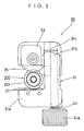
- Fig. 1 is a plan view of a connecting structure of a coaxial cable with a connector according to a preferred embodiment of the invention;
- Fig. 2(a) is a side sectional view of a main part of a coaxial cable according to a preferred embodiment of the invention illustrating a process of cutting an outer conductor of the coaxial cable;
- Fig. 2(b) is a side sectional view of a main part of a coaxial cable according to a preferred embodiment of the invention illustrating removal of an insulator exposed by the cutting of an outer conductor;
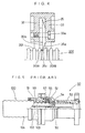
- Fig. 3 is a plan view showing the structure of a cutting tool according to a preferred embodiment of the invention used for cutting a coaxial cable;
- Fig. 4 is a side view of a main part of the same cutting tool; and
- Fig. 5 is a side view with the upper half partly cut away showing a conventional connection between a coaxial cable and a connector.
- Referring to Fig. 1, a
coaxial cable 200 has as an annular corrugated tube anouter conductor 201 with ridges in its outer surface. Acorrosion preventing layer 202 is formed on the outer surface of theouter conductor 201. Aninsulator 203 is formed on the inner surface side of theouter conductor 201. Aninner conductor 204 is disposed inside theinsulator 203. Theouter conductor 201 and theinner conductor 204 are electrically insulated from each other by theinsulator 203. Theouter conductor 201 as seen from outside is formed as an annular corrugated tube whereingrooves 201A andridges 201B are alternately repeated. - As the
outer conductor 201 used in this preferred embodiment, for example one of which the internal diameter at thegrooves 201A is 9.3mm, the pitch of theridges 201B is 3.0mm and the depth of the grooves is 1.3mm is used. That is, the width of theridges 201B is small and the side wall surfaces thereof are steep. - The following preparation of the
coaxial cable 200 is carried out before it is connected to a connector 1: The end of thecoaxial cable 200 is treated to make it straight over a predetermined length suited to the axial direction dimensions of theconnector 1, for example about 100mm. Thecorrosion preventing layer 202 constituting the outermost layer of thecoaxial cable 200 and consisting of for example polyethylene is cut circumferentially and removed over a predetermined length from the end of thecoaxial cable 200. The position of the cut end of thecorrosion preventing layer 202 is so set that it is aligned with a central position of agroove 201A of theouter conductor 201. The length of thecorrosion preventing layer 202 so peeled off is determined according to the axial dimensions of theconnector 1. - After the
corrosion preventing layer 202 is thus peeled off, theouter conductor 201 is cut from the end of thecoaxial cable 200 over a predetermined length suited to the axial dimensions of theconnector 1, for example 8 to 9mm, the cutting being carried out at agroove 201A in a predetermined position. This cut state is shown in Fig. 2(b). - The
insulator 203 exposed as a result of this cutting is removed. As a result of the removal of thisinsulator 203 theinner conductor 204 is exposed as shown in Fig. 2(b). The exposedinner conductor 204 is chamfered using a flat file. - The method by which the
outer conductor 201 is cut will now be described. Cutting of theouter conductor 201 is carried out using acutting tool 30 shown in Fig. 3 and Fig. 4. - The construction of the
cutting tool 30 will now be described. The cuttingtool 30 has an L-shapedsupport member 31. A pair ofguide rollers end 31a of thesupport member 31 a predetermined distance apart from each other. A pair of holdingmembers other end 31b of thesupport member 31. The pair of holdingmembers rotary shaft 33a mounted therebetween. The pair ofguide rollers members inner side surface 31c of thesupport member 31. Afeed screw 34 serving as a relative movement mechanism is rotatably housed inside theend 31b of thesupport member 31. The pair of holdingmembers feed screw 34 in the length direction of theend 31b of thesupport member 31, i.e. the direction in which the holdingmembers guide rollers cutting blade 35 is rotatably mounted on therotary shaft 33a between the holdingmembers cutting blade 35 faces the pair ofguide rollers rotary shaft 33a on which thecutting blade 35 is mounted and rotary shafts not shown in the drawings on which the pair ofguide rollers support member 31, i.e. a direction perpendicular to the paper surface. - A characteristic feature of the
cutting tool 30 is the structure of thecutting blade 35. That is, of the two sides of thecutting edge 35c of thecutting blade 35, onecutting edge side 35a is sloping with respect to the radial direction of thecutting blade 35 and the othercutting edge side 35b is perpendicular to the axial direction of thecutting blade 35. - In cutting the
outer conductor 201 of thecoaxial cable 100 using thiscutting tool 30, first, to make it possible to position thecoaxial cable 200, thefeed screw 34 is operated and the pair of holdingmembers guide rollers coaxial cable 200 with thecorrosion preventing layer 202 already peeled off and theouter conductor 201 thereby exposed is then positioned between the cuttingblade 35 and theguide rollers cutting blade 35 is brought into line with agroove 201A at a predetermined position. Thefeed screw 34 is then operated and thecutting blade 35 is moved toward theguide rollers cutting tool 30 is finely moved in the axial direction of thecoaxial cable 200 until thecutting edge side 35b of thecutting edge 35c of thecutting blade 35 almost abuts with the side wall surface of theridge 201B adjacent to thegroove 201A of theouter conductor 201 on the same side of thegroove 201A as the axial center of thecoaxial cable 200, that is, on the right side thereof in Fig. 4. When this is being done, because as described above thecutting edge side 35b is perpendicular to the axial direction of thecutting blade 35, thecutting blade 35 can be moved in the axial direction of thecoaxial cable 200 until thecutting edge 35c of thecutting blade 35 is positioned at the side wall of theridge 201B. - A
knob 34a attached to thefeed screw 34 is then further turned to rotate thefeed screw 34 and cause thecutting blade 35 to cut to some extent into the surface of thegroove 201A of theouter conductor 201 in said predetermined position. Theouter conductor 201 is then cut by the cuttingtool 30 in this state being rotated about thecoaxial cable 200 by hand. This turning of thecutting blade 35 is carried out by hand as described above, but because theguide rollers outer conductor 201 and thecutting blade 35 also rotates along the outer surface of theouter conductor 201, even with a relatively small force it is possible to rotate thecoaxial cable 200 easily by hand. - In this way, the cut position of the
outer conductor 201 cut from thecoaxial cable 200 is not the middle of thegroove 201A of the predetermined position but is a position near theridge 201B adjacent to thegroove 201A on the same side thereof as the axial center of thecoaxial cable 200. - The
coaxial cable 200 having had its end prepared as described above is connected to theconnector 1 as described below with reference to Fig. 1. Theconnector 1 comprises acap nut 2 serving as a clamping member moving member fitting on the outside of the connection end of thecoaxial cable 200 and amain body 3 serving as one clamping member connected by a screw thread to thecap nut 2. Asplit clamp 4 serving as another clamping member is disposed between thecap nut 2 and themain body 3. Thesplit clamp 4 is made up of a clampingpart 4a, a pushed-uponpart 4b and a joiningpart 4c joining these together. Acoupling nut 5 is rotatably mounted on the outside of themain body 3. Acentral connector 6 is mounted inside themain body 3 with aninsulator 7 disposed therebetween. A side of thecentral connector 6 to which theinner conductor 204 is connected constitutes a tubular part 208, and a plurality of slits 209 are formed in the tubular part 208 in the axial direction. The provision of these slits 209 make it possible for the tubular part 208 to widen; by widening, the tubular part 208 firmly holds theinner conductor 204 when it is fitted into the tubular part 208, and in this way electrical connection of theinner conductor 204 to thecentral connector 6 is stably effected. As a result of having the constitution described above thesplit clamp 4 has an inner surface shape which covers aridge 201B of theouter conductor 201 of thecoaxial cable 200, and thesplit clamp 4 is made up of a pair of circular arc shaped ringlike members not fully shown in the drawings fitting around the outside of theouter conductor 201 and a member which with the ringlike members positioned around the outer surface of aridge 201B of theouter conductor 201 holds the ringlike members together on the outer surface of theridge 201B as a split clamp. - Connection of the
coaxial cable 200 using theconnector 1 will now be described. - With the
coaxial cable 200 inserted into theconnector 1 through an opening in themain body 3, thesplit clamp 4 is fitted onto thesecond ridge 201B of theouter conductor 201 from the end of thecoaxial cable 200. Thecap nut 2 is then screwed into themain body 3 so that thesplit clamp 4 fitted over theridge 201B of theouter conductor 201 is clamped from both sides. By this screwing action thesplit clamp 4 is clamped between a receivingseat 2a provided on thecap nut 2 and a receivingseat 3a provided on themain body 3. By tightening thecap nut 2 thesplit clamp 4 is moved toward the left in Fig. 1, and as a result of this thefirst ridge 201B of theouter conductor 201 is clamped between thesplit clamp 4 and the receivingseat 3a of themain body 3 and as this clamping force increases is squashed into a flange shape. This squashing of theridge 201B is effected smoothly with a small force because the width of theridge 201B is small and the side wall surfaces of theridge 201B are steep. - In this way, the
outer conductor 201 of thecoaxial cable 200 is firmly electrically and mechanically connected to theconnector 1 by way of themain body 3. Also, simultaneously with this connection of theouter conductor 201, theinner conductor 204 fits into the tubular part 208 of thecentral connector 6 and connection of theinner conductor 204 is also effected. Thus, connection of theouter conductor 201 and theinner conductor 204 to theconnector 1 is performed easily just by tightening thecap nut 2. - The
outer conductor 201 of thecoaxial cable 200 is connected to theconnector 1 in this way, and at the time of this connection theridge 201B at the end of theouter conductor 201 is squashed and becomes aflange portion 205 and theouter conductor 201 is connected to theconnector 1 by way of thisflange portion 205. Therefore, the work of widening the end of theouter conductor 201 radially outward as has been done conventionally becomes unnecessary. Theflange portion 205 is automatically created when thecap nut 2 and themain body 3 of theconnector 1 are joined together. - In this point, the work of connecting the
connector 1 to thecoaxial cable 200 is greatly reduced compared to a conventional case. Labor costs are also reduced as a result of this reduction in the connection work. Furthermore, because a special tool for widening the end of theouter conductor 201 radially outward becomes unnecessary, tooling costs can also be reduced. - Also, because cutting of the
outer conductor 201 is carried out at agroove 201A, compared to when cutting of a ridge is carried out, because guiding members and the like not necessary, the cutting work is simple and cutting costs can be reduced. - In particular, because the cutting position of the
outer conductor 201 is a position near aridge 201B, even if thisridge 201B is squashed as described above, the cut end of theouter conductor 201 is not positioned further on the radially inner side of thecoaxial cable 200 than agroove 201A. Therefore, even after theridge 201B of theouter conductor 201 is squashed, the separation distance between theouter conductor 201 and theinner conductor 204 at the cut end of theouter conductor 201 remains substantially the same as the separation distance between theouter conductor 201 and theinner conductor 204 elsewhere in the cable, and high frequency transmission path impedance fluctuation caused by variations in this separation distance is suppressed. - While the invention has been particularly shown and described with reference to preferred embodiments thereof, it will be understood by those skilled in the art that the foregoing and other changes in form and details can be made therein without departing from the spirit and scope of the invention.
Claims (11)
- A method for electrically connecting an annular corrugated tube comprising the steps of:cutting at a groove an annular corrugated tube having an outer surface shape wherein grooves and ridges are alternately repeated in the axial direction of the tube in a wave form;disposing a clamping member on each side of a ridge at the cut end of the tube; andelectrically connecting the tube to the clamping member positioned on the cut end of the tube side of the ridge by squashing the ridge with the clamping members.
- A method for electrically connecting an annular corrugated tube according to claim 1 wherein said ridge is the first ridge from the cut end.
- A method for electrically connecting an annular corrugated tube according to claim 1 wherein an annular corrugated tube of which the ratio of the depth of the grooves to the pitch of the ridges is 1 .0 : 2.0 to 2.5 is used.
- A method for electrically connecting an annular corrugated tube according to claim 1 wherein cutting of the annular corrugated tube is carried out using a cutting blade only one side of the cutting edge of which has a sloping surface.
- A method for connecting a coaxial cable wherein in claims 1 through 4 the annular corrugated tube is an outer conductor of a coaxial cable and the clamping member positioned on the cut end of the tube side of the ridge is a part of a connector attached to the end of the coaxial cable.
- A method for connecting a coaxial cable according to claim 5 wherein the clamping member positioned on the opposite side of the ridge from the cut end of the annular corrugated tube is a split clamp.
- A structure for electrically connecting an annular corrugated tube comprising:an annular corrugated tube having an outer surface shape wherein grooves and ridges are alternately repeated in the axial direction of the tube in a wave form and having one end cut at a groove;clamping members one of which is disposed on each side of the first ridge from the cut end of the annular corrugated tube; anda clamping member's moving member for making the clamping members move toward each other,wherein by an operation of the clamping member's moving member causing the clamping members to squash the first ridge the annular corrugated tube is electrically connected to the clamping member positioned on the cut end of the tube side of the ridge.
- A structure for electrically connecting a coaxial cable wherein in claim 7 the annular corrugated tube is an outer conductor of a coaxial cable and the clamping member positioned on the cut end of the tube side of the ridge is a part of a connector attached to the end of the coaxial cable.
- A structure for electrically connecting a coaxial cable according to claim 8 wherein the clamping member positioned on the opposite side of the ridge from the cut end of the annular corrugated tube is a split clamp attached to the annular corrugated tube.
- A structure for electrically connecting a coaxial cable according to claim 7, 8 or 9 wherein the clamping member's moving member is a cap nut screwed to a part of the connector.
- A structure for electrically connecting a coaxial cable according to claim 8 wherein the end of an inner conductor of the coaxial cable projects beyond the end of the outer conductor and an inner conductor connecting and fitting part to which the inner conductor fits is provided inside the connector and when the outer conductor is connected to the connector the end of the inner conductor is fitted to the inner conductor connecting and fitting part.
Applications Claiming Priority (3)
| Application Number | Priority Date | Filing Date | Title |
|---|---|---|---|
| JP309995 | 1995-01-12 | ||
| JP3099/95 | 1995-01-12 | ||
| JP7003099A JP2913373B2 (en) | 1995-01-12 | 1995-01-12 | Method of connecting ring-shaped corrugated tube and connection structure thereof |
Publications (3)
| Publication Number | Publication Date |
|---|---|
| EP0722199A2 true EP0722199A2 (en) | 1996-07-17 |
| EP0722199A3 EP0722199A3 (en) | 1997-07-23 |
| EP0722199B1 EP0722199B1 (en) | 2003-05-21 |
Family
ID=11547906
Family Applications (1)
| Application Number | Title | Priority Date | Filing Date |
|---|---|---|---|
| EP96100182A Expired - Lifetime EP0722199B1 (en) | 1995-01-12 | 1996-01-08 | Method and structure for electrically connecting an annular corrugated tube |
Country Status (7)
| Country | Link |
|---|---|
| US (1) | US5871372A (en) |
| EP (1) | EP0722199B1 (en) |
| JP (1) | JP2913373B2 (en) |
| KR (1) | KR100242450B1 (en) |
| CN (1) | CN1080000C (en) |
| DE (1) | DE69628215T2 (en) |
| TW (1) | TW302570B (en) |
Cited By (4)
| Publication number | Priority date | Publication date | Assignee | Title |
|---|---|---|---|---|
| FR2753572A1 (en) * | 1996-09-14 | 1998-03-20 | Spinner Gmbh Elektrotech | MALE-FEMALE CONNECTION PLUG FOR COAXIAL CABLE |
| US5766037A (en) * | 1996-10-11 | 1998-06-16 | Radio Frequency Systems, Inc. | Connector for a radio frequency cable |
| EP0938165A1 (en) * | 1998-02-19 | 1999-08-25 | Alcatel | Coaxial high frequency cable connector |
| EP0955701A2 (en) * | 1998-04-06 | 1999-11-10 | Andrew A.G. | One piece connector for a coaxial cable with an annularly corrugated outer conductor |
Families Citing this family (12)
| Publication number | Priority date | Publication date | Assignee | Title |
|---|---|---|---|---|
| US5944556A (en) * | 1997-04-07 | 1999-08-31 | Andrew Corporation | Connector for coaxial cable |
| EP1148592A1 (en) | 2000-04-17 | 2001-10-24 | Cabel-Con A/S | Connector for a coaxial cable with corrugated outer conductor |
| US7261581B2 (en) * | 2003-12-01 | 2007-08-28 | Corning Gilbert Inc. | Coaxial connector and method |
| US6955562B1 (en) * | 2004-06-15 | 2005-10-18 | Corning Gilbert Inc. | Coaxial connector with center conductor seizure |
| US7077700B2 (en) * | 2004-12-20 | 2006-07-18 | Corning Gilbert Inc. | Coaxial connector with back nut clamping ring |
| US7416788B2 (en) * | 2005-06-30 | 2008-08-26 | Honeywell International Inc. | Thermal barrier coating resistant to penetration by environmental contaminants |
| US8460031B2 (en) * | 2008-11-05 | 2013-06-11 | Andrew Llc | Coaxial connector with cable diameter adapting seal assembly and interconnection method |
| JP5741138B2 (en) * | 2011-03-30 | 2015-07-01 | 株式会社ノーリツ | Manufacturing method of flange-integrated corrugated pipe, flange-integrated corrugated pipe, and cutting apparatus for corrugated pipe used in the manufacturing method |
| CN104065025A (en) * | 2014-06-13 | 2014-09-24 | 苏州华徕光电仪器有限公司 | Cable coupler capable of changing transmission directions |
| KR101630684B1 (en) * | 2014-12-30 | 2016-06-16 | 농업회사법인 에이앤피테크놀로지주식회사 | Rf coaxial connector |
| JP6451568B2 (en) * | 2015-09-14 | 2019-01-16 | 株式会社オートネットワーク技術研究所 | Shield connector |
| CN108777392B (en) * | 2018-08-07 | 2021-03-16 | 江苏亨鑫科技有限公司 | High-reliability radio frequency coaxial connector capable of being quickly disassembled and assembled |
Citations (3)
| Publication number | Priority date | Publication date | Assignee | Title |
|---|---|---|---|---|
| US3708853A (en) * | 1971-04-15 | 1973-01-09 | Gen Cable Corp | Wire terminating machine |
| DE4207482C1 (en) * | 1992-03-10 | 1993-07-08 | Wilhelm Sihn Jun. Kg, 7532 Niefern-Oeschelbronn, De | Forming flanged rim in waveguide of coaxial cable - allowing armature to be mounted with bearing clamped to fit in troughs of waveguide pushed to abut bearing |
| US5284449A (en) * | 1993-05-13 | 1994-02-08 | Amphenol Corporation | Connector for a conduit with an annularly corrugated outer casing |
Family Cites Families (5)
| Publication number | Priority date | Publication date | Assignee | Title |
|---|---|---|---|---|
| JPS5895137U (en) * | 1981-12-21 | 1983-06-28 | 三菱電線工業株式会社 | Terminal of corrugated tube |
| JPH0410978Y2 (en) * | 1986-11-07 | 1992-03-18 | ||
| JPS6455586U (en) * | 1987-09-28 | 1989-04-06 | ||
| US4995832A (en) * | 1989-10-26 | 1991-02-26 | Specialty Connector Company, Inc. | Connector for connecting to helically corrugated conduit |
| JPH0419716U (en) * | 1990-06-06 | 1992-02-19 |
-
1995
- 1995-01-12 JP JP7003099A patent/JP2913373B2/en not_active Expired - Lifetime
- 1995-12-30 TW TW084114204A patent/TW302570B/zh active
-
1996
- 1996-01-05 US US08/583,711 patent/US5871372A/en not_active Expired - Fee Related
- 1996-01-08 EP EP96100182A patent/EP0722199B1/en not_active Expired - Lifetime
- 1996-01-08 DE DE69628215T patent/DE69628215T2/en not_active Expired - Fee Related
- 1996-01-11 CN CN96100423A patent/CN1080000C/en not_active Expired - Fee Related
- 1996-01-12 KR KR1019960000509A patent/KR100242450B1/en not_active IP Right Cessation
Patent Citations (3)
| Publication number | Priority date | Publication date | Assignee | Title |
|---|---|---|---|---|
| US3708853A (en) * | 1971-04-15 | 1973-01-09 | Gen Cable Corp | Wire terminating machine |
| DE4207482C1 (en) * | 1992-03-10 | 1993-07-08 | Wilhelm Sihn Jun. Kg, 7532 Niefern-Oeschelbronn, De | Forming flanged rim in waveguide of coaxial cable - allowing armature to be mounted with bearing clamped to fit in troughs of waveguide pushed to abut bearing |
| US5284449A (en) * | 1993-05-13 | 1994-02-08 | Amphenol Corporation | Connector for a conduit with an annularly corrugated outer casing |
Cited By (6)
| Publication number | Priority date | Publication date | Assignee | Title |
|---|---|---|---|---|
| FR2753572A1 (en) * | 1996-09-14 | 1998-03-20 | Spinner Gmbh Elektrotech | MALE-FEMALE CONNECTION PLUG FOR COAXIAL CABLE |
| US5766037A (en) * | 1996-10-11 | 1998-06-16 | Radio Frequency Systems, Inc. | Connector for a radio frequency cable |
| EP0938165A1 (en) * | 1998-02-19 | 1999-08-25 | Alcatel | Coaxial high frequency cable connector |
| US6102737A (en) * | 1998-02-19 | 2000-08-15 | Alcatel | Connecting element for a coaxial high-frequency cable |
| EP0955701A2 (en) * | 1998-04-06 | 1999-11-10 | Andrew A.G. | One piece connector for a coaxial cable with an annularly corrugated outer conductor |
| EP0955701A3 (en) * | 1998-04-06 | 2000-05-17 | Andrew A.G. | One piece connector for a coaxial cable with an annularly corrugated outer conductor |
Also Published As
| Publication number | Publication date |
|---|---|
| KR100242450B1 (en) | 2000-02-01 |
| CN1080000C (en) | 2002-02-27 |
| JPH08190965A (en) | 1996-07-23 |
| US5871372A (en) | 1999-02-16 |
| EP0722199A3 (en) | 1997-07-23 |
| DE69628215T2 (en) | 2004-03-18 |
| TW302570B (en) | 1997-04-11 |
| JP2913373B2 (en) | 1999-06-28 |
| DE69628215D1 (en) | 2003-06-26 |
| CN1134049A (en) | 1996-10-23 |
| KR960030491A (en) | 1996-08-17 |
| EP0722199B1 (en) | 2003-05-21 |
Similar Documents
| Publication | Publication Date | Title |
|---|---|---|
| EP0722199B1 (en) | Method and structure for electrically connecting an annular corrugated tube | |
| EP0495467B1 (en) | Self-flaring connector for coaxial cable having a helically corrugated outer conductor | |
| US7134189B2 (en) | Coaxial cable connector and tool and method for connecting a coaxial cable | |
| US5284449A (en) | Connector for a conduit with an annularly corrugated outer casing | |
| US4421377A (en) | Connector for HF coaxial cable | |
| EP0517034B1 (en) | Connector for coaxial cable having a helically corrugated inner conductor | |
| US5766037A (en) | Connector for a radio frequency cable | |
| US6168455B1 (en) | Coaxial cable connector | |
| US7357671B2 (en) | Coaxial plug-type connector and method for mounting the same | |
| EP0484434B1 (en) | Cable collet termination | |
| EP0657068B1 (en) | Connector for coaxial cable having corrugated outer conductor and method of attachment | |
| US3544705A (en) | Expandable cable bushing | |
| US5830009A (en) | Device for connecting a coaxial plug to a coaxial cable | |
| EP0167738A2 (en) | Electrical connector having means for retaining a coaxial cable | |
| EP0577710A1 (en) | Coaxial cable connector with mandrel spacer and method of preparing coaxial cable | |
| JPH05275144A (en) | Connector assembly | |
| EP1284031B1 (en) | Cable lug | |
| AU2001256501A1 (en) | Cable lug | |
| GB2299467A (en) | Connector for a hollow center conductor of a radio frequency cable | |
| EP0695001B1 (en) | Metal terminal insertion tool for inserting a metal terminal within a connector housing | |
| US7059162B1 (en) | Dual flaring tool | |
| US5888095A (en) | Coaxial cable connector | |
| CA1145430A (en) | Method of and electrical termination for coaxial cable | |
| JP3012286U (en) | Coaxial cable connector | |
| JPH10172679A (en) | Connector for coaxial cable |
Legal Events
| Date | Code | Title | Description |
|---|---|---|---|
| PUAI | Public reference made under article 153(3) epc to a published international application that has entered the european phase |
Free format text: ORIGINAL CODE: 0009012 |
|
| AK | Designated contracting states |
Kind code of ref document: A2 Designated state(s): DE GB IT SE |
|
| PUAL | Search report despatched |
Free format text: ORIGINAL CODE: 0009013 |
|
| AK | Designated contracting states |
Kind code of ref document: A3 Designated state(s): DE GB IT SE |
|
| 17P | Request for examination filed |
Effective date: 19971103 |
|
| 17Q | First examination report despatched |
Effective date: 20000509 |
|
| GRAG | Despatch of communication of intention to grant |
Free format text: ORIGINAL CODE: EPIDOS AGRA |
|
| GRAG | Despatch of communication of intention to grant |
Free format text: ORIGINAL CODE: EPIDOS AGRA |
|
| GRAH | Despatch of communication of intention to grant a patent |
Free format text: ORIGINAL CODE: EPIDOS IGRA |
|
| GRAH | Despatch of communication of intention to grant a patent |
Free format text: ORIGINAL CODE: EPIDOS IGRA |
|
| RIC1 | Information provided on ipc code assigned before grant |
Free format text: 7H 01R 9/05 A, 7H 01R 13/646 B |
|
| GRAA | (expected) grant |
Free format text: ORIGINAL CODE: 0009210 |
|
| AK | Designated contracting states |
Designated state(s): DE GB IT SE |
|
| PG25 | Lapsed in a contracting state [announced via postgrant information from national office to epo] |
Ref country code: IT Free format text: LAPSE BECAUSE OF FAILURE TO SUBMIT A TRANSLATION OF THE DESCRIPTION OR TO PAY THE FEE WITHIN THE PRESCRIBED TIME-LIMIT;WARNING: LAPSES OF ITALIAN PATENTS WITH EFFECTIVE DATE BEFORE 2007 MAY HAVE OCCURRED AT ANY TIME BEFORE 2007. THE CORRECT EFFECTIVE DATE MAY BE DIFFERENT FROM THE ONE RECORDED. Effective date: 20030521 |
|
| REG | Reference to a national code |
Ref country code: GB Ref legal event code: FG4D |
|
| REF | Corresponds to: |
Ref document number: 69628215 Country of ref document: DE Date of ref document: 20030626 Kind code of ref document: P |
|
| REG | Reference to a national code |
Ref country code: SE Ref legal event code: TRGR |
|
| PG25 | Lapsed in a contracting state [announced via postgrant information from national office to epo] |
Ref country code: GB Free format text: LAPSE BECAUSE OF NON-PAYMENT OF DUE FEES Effective date: 20040108 |
|
| PGFP | Annual fee paid to national office [announced via postgrant information from national office to epo] |
Ref country code: SE Payment date: 20040119 Year of fee payment: 9 |
|
| PGFP | Annual fee paid to national office [announced via postgrant information from national office to epo] |
Ref country code: DE Payment date: 20040121 Year of fee payment: 9 |
|
| PLBE | No opposition filed within time limit |
Free format text: ORIGINAL CODE: 0009261 |
|
| STAA | Information on the status of an ep patent application or granted ep patent |
Free format text: STATUS: NO OPPOSITION FILED WITHIN TIME LIMIT |
|
| 26N | No opposition filed |
Effective date: 20040224 |
|
| GBPC | Gb: european patent ceased through non-payment of renewal fee |
Effective date: 20040108 |
|
| PG25 | Lapsed in a contracting state [announced via postgrant information from national office to epo] |
Ref country code: SE Free format text: LAPSE BECAUSE OF NON-PAYMENT OF DUE FEES Effective date: 20050109 |
|
| PG25 | Lapsed in a contracting state [announced via postgrant information from national office to epo] |
Ref country code: DE Free format text: LAPSE BECAUSE OF NON-PAYMENT OF DUE FEES Effective date: 20050802 |
|
| EUG | Se: european patent has lapsed |