EP0722046A2 - Vorrichtung zum Führen einer Linearbewegung - Google Patents
Vorrichtung zum Führen einer Linearbewegung Download PDFInfo
- Publication number
- EP0722046A2 EP0722046A2 EP95850209A EP95850209A EP0722046A2 EP 0722046 A2 EP0722046 A2 EP 0722046A2 EP 95850209 A EP95850209 A EP 95850209A EP 95850209 A EP95850209 A EP 95850209A EP 0722046 A2 EP0722046 A2 EP 0722046A2
- Authority
- EP
- European Patent Office
- Prior art keywords
- rail
- guide rail
- housing
- fastening
- holders
- Prior art date
- Legal status (The legal status is an assumption and is not a legal conclusion. Google has not performed a legal analysis and makes no representation as to the accuracy of the status listed.)
- Granted
Links
Images

Classifications
-
- B—PERFORMING OPERATIONS; TRANSPORTING
- B23—MACHINE TOOLS; METAL-WORKING NOT OTHERWISE PROVIDED FOR
- B23Q—DETAILS, COMPONENTS, OR ACCESSORIES FOR MACHINE TOOLS, e.g. ARRANGEMENTS FOR COPYING OR CONTROLLING; MACHINE TOOLS IN GENERAL CHARACTERISED BY THE CONSTRUCTION OF PARTICULAR DETAILS OR COMPONENTS; COMBINATIONS OR ASSOCIATIONS OF METAL-WORKING MACHINES, NOT DIRECTED TO A PARTICULAR RESULT
- B23Q1/00—Members which are comprised in the general build-up of a form of machine, particularly relatively large fixed members
- B23Q1/25—Movable or adjustable work or tool supports
- B23Q1/26—Movable or adjustable work or tool supports characterised by constructional features relating to the co-operation of relatively movable members; Means for preventing relative movement of such members
-
- B—PERFORMING OPERATIONS; TRANSPORTING
- B23—MACHINE TOOLS; METAL-WORKING NOT OTHERWISE PROVIDED FOR
- B23Q—DETAILS, COMPONENTS, OR ACCESSORIES FOR MACHINE TOOLS, e.g. ARRANGEMENTS FOR COPYING OR CONTROLLING; MACHINE TOOLS IN GENERAL CHARACTERISED BY THE CONSTRUCTION OF PARTICULAR DETAILS OR COMPONENTS; COMBINATIONS OR ASSOCIATIONS OF METAL-WORKING MACHINES, NOT DIRECTED TO A PARTICULAR RESULT
- B23Q1/00—Members which are comprised in the general build-up of a form of machine, particularly relatively large fixed members
- B23Q1/01—Frames, beds, pillars or like members; Arrangement of ways
- B23Q1/017—Arrangements of ways
-
- F—MECHANICAL ENGINEERING; LIGHTING; HEATING; WEAPONS; BLASTING
- F16—ENGINEERING ELEMENTS AND UNITS; GENERAL MEASURES FOR PRODUCING AND MAINTAINING EFFECTIVE FUNCTIONING OF MACHINES OR INSTALLATIONS; THERMAL INSULATION IN GENERAL
- F16C—SHAFTS; FLEXIBLE SHAFTS; ELEMENTS OR CRANKSHAFT MECHANISMS; ROTARY BODIES OTHER THAN GEARING ELEMENTS; BEARINGS
- F16C29/00—Bearings for parts moving only linearly
- F16C29/04—Ball or roller bearings
- F16C29/045—Ball or roller bearings having rolling elements journaled in one of the moving parts
-
- F—MECHANICAL ENGINEERING; LIGHTING; HEATING; WEAPONS; BLASTING
- F16—ENGINEERING ELEMENTS AND UNITS; GENERAL MEASURES FOR PRODUCING AND MAINTAINING EFFECTIVE FUNCTIONING OF MACHINES OR INSTALLATIONS; THERMAL INSULATION IN GENERAL
- F16C—SHAFTS; FLEXIBLE SHAFTS; ELEMENTS OR CRANKSHAFT MECHANISMS; ROTARY BODIES OTHER THAN GEARING ELEMENTS; BEARINGS
- F16C2322/00—Apparatus used in shaping articles
- F16C2322/39—General build up of machine tools, e.g. spindles, slides, actuators
Definitions
- This invention concerns a device according to the preamble of claim 1 and a fluid pressure cylinder, of the type having a slot, comprising such a device.
- US-A-4,877,338 describes a linear power device with a slot cylinder, on its housing being provided with a guide rail which is fastened by means of two profiled strips. Each of the profiled strips cooperate on the one hand with grooves in the cylinder housing, on the other hand with grooves in the guide rail to be fastened. The desired fastening is achieved by clamping the profiled strips together.
- This known device is complex and costly, inter alia because of the necessity of using a special guide rail having grooves corresponding to the profiled elements. Further, the fastening procedure is complex since mounting in principle must be undertaken axially. Mounting sideways onto the cylinder would require a considerable working length for the screws holding the profiled elements together.
- an uncomplicated guide rail may be used and that the fastening screws for the guide rail are used for obtaining the fixation.
- profiled elements are used which advantageously may be manufactured in a continuous process from an aluminium containing material altogether resulting in a very advantageous solution with respect to costs.
- the guide rail itself is thus used as a part of a link mechanism in order to obtain an uncomplicated as well as simply and quickly fastenable guide rail device.
- the invention also concerns a fluid pressure cylinder of the slot cylinder type which is provided with a device according to any of the claims 1-6.
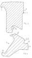
- Fig. 1 thus shows a housing 1' having a drive element which is connected over power transferring means 3 to a guiding slide 4.
- the slide 4 is longitudinally movable along a guide rail 5 which is fixed on the housing 1' by means of an arrangement of rail holders 6 and 7.
- the guide rail 5 is fastened by means of fastening screws 9 (one of which is shown in the fig) onto a first rail holder 6, by the fastening screws being in engagement with holes therein. Further, the guide rail 5 is provided with a bore for the fastening screw 9 allowing a certain mutual turning movement between said fastening screw and the guide rail.
- the guide rail 5 further presses by means of a first pressing surface (at 11), against a first counter-pressure surface (likewise at 11), at the sideways outer portion of that side of the guide rail which is turned against the cylinder.
- the guide rail 5 acts with a second pressing surface (at 12) against a second counter-pressure surface (likewise at 12) on the second rail holder 7.
- this second rail holder 7 over a strip portion 10" grips into a corresponding groove 10' in the first rail holder 6 such that pivot surfaces (at 10) are formed in the area of contact between the strip portion 10" and the groove 10' so as to allow a limited pivoting movement of the rail holders 6 and 7 relative to each other around this area.
- the strip portion 10" and the groove 10' are shaped in such a way that the tensioning of the fastening screw 9 binds the said rail holders 6 and 7 to each other, at least in such a way that sliding sidewards of the strip portion out of the groove is prevented.
- the rail holders 6 and 7 are provided with first 14 and second 15 strip elements respectively for gripping on corresponding dovetail-shaped projecting engagement elements 16 on the housing.
- the embodiment of the invention shown in the figures functions as follows: in an assembled state which is shown in fig. 2, the pivot surfaces at 10 and the first 11 and the second 12 respectively counter-pressure/pressing surfaces form corners of a triangle. By tensioning fastening screws 9 this triangle is deformed in such a way that a plier-like turning of the rail holders 6 and 7 occurs around the pivot surfaces 10, whereby the distance between the first 14 and the second strip element is reduced which in the mounting position will lead to clamping of the entire unit consisting of rail holders 6 and 7 and guide rail 5 and fastening screws 9 onto the engagement element 16 of the housing.
- the second rail holder 7 is provided with a strip-like projection 17, which carries a supporting surface 13 extending in an angle with respect to the second counter-pressure surface 12 and said support surface 13 providing a sideward support for a corresponding surface on the guide rail 5.
- the mounting of the guiding device onto a cylinder is achieved by firstly placing the two rail holders, possibly by aid of a fastening device, with the gripping elements 14, 15 just opposite the corresponding engagement elements 16 on the housing, whereafter the guide rail having the power transmitting means 3, 4 mounted thereon is fastened during continuous control of the alignment of the guide rail by successive tensioning of the fastening screws with a simultaneous displacement movement of the shuttle.
- Fig. 3 shows in an enlarged scale the first rail holder 6 with counter-pressure surface 11.1, groove 10' with pivot surface 10.1 and the first strip element 14.
- Fig. 4 shows in an enlarged scale the second rail holder 7 with counter-pressure surface 12.2, strip portion 10" with pivot surface 10.2, strip element 15 and, projecting from the cylinder, a projection 17 which on the side which in use is turned against the guide rail provides a supporting surface 13 for support against a corresponding surface on the guide rail.
- the invention is not limited to the shown embodiment but only to what is stated in the following claims. It is thus within the scoop of this invention also to form the rail holders in three parts, in principle two parts resembling detail 7 and a intermediate supporting portion for providing pivot surfaces and for providing tension against the guide rail by means of the fastening screws. In that case the surfaces form the corners of a quadrangle. It is, however stressed that the shown embodiment is preferred because of a minimal number of components, simpler mounting as well as that added tolerances are limited and thus enhanced alignment accuracy.
- the extruded profiles may be used directly, in others where greater accuracy is necessary, it may be necessary to straighten the extruded profiles.
- the material of the rail holders is preferably aluminium or a suitable alloy including aluminium. If the rail holders are not extruded other materials may come into question.
- the rail holders are extending along the entire length of the cylinder which provides particularly good force distribution along the cylinder and contributes to particularly good linear alignment of the guide rail.
- a number of devices according to the invention may be distributed axially along the cylinder for fastening a guide rail. These "rail holding packages" are in that case discrete units along the length of the cylinder.
- a solution according to the invention provides the possibility of constructing a rigid construction having good force withstanding properties. This is particularly important in applications where large masses are moved by the power unit and/or when accelerations are considerable etc.
- the invention provides a possibility of rugged construction of the guiding device as well as cylinder tubes having engagement surfaces carrying form parts.
Landscapes
- Engineering & Computer Science (AREA)
- Mechanical Engineering (AREA)
- General Engineering & Computer Science (AREA)
- Bearings For Parts Moving Linearly (AREA)
- Transmission Devices (AREA)
- Actuator (AREA)
Applications Claiming Priority (2)
| Application Number | Priority Date | Filing Date | Title |
|---|---|---|---|
| SE9404412 | 1994-12-19 | ||
| SE9404412A SE9404412L (sv) | 1994-12-19 | 1994-12-19 | Anordning för linjärstyrning hos ett kraftaggregat samt en tryckfluidcylinder av slitscylindertyp |
Publications (3)
| Publication Number | Publication Date |
|---|---|
| EP0722046A2 true EP0722046A2 (de) | 1996-07-17 |
| EP0722046A3 EP0722046A3 (de) | 1998-02-25 |
| EP0722046B1 EP0722046B1 (de) | 2000-09-20 |
Family
ID=20396386
Family Applications (1)
| Application Number | Title | Priority Date | Filing Date |
|---|---|---|---|
| EP95850209A Expired - Lifetime EP0722046B1 (de) | 1994-12-19 | 1995-11-27 | Vorrichtung zum Führen einer Linearbewegung |
Country Status (3)
| Country | Link |
|---|---|
| EP (1) | EP0722046B1 (de) |
| DE (1) | DE69518905T2 (de) |
| SE (1) | SE9404412L (de) |
Cited By (3)
| Publication number | Priority date | Publication date | Assignee | Title |
|---|---|---|---|---|
| EP0899232A2 (de) * | 1997-08-28 | 1999-03-03 | Nissan Motor Co., Ltd. | Verbindungstruktur für die Hebecylinder einer Lasthabungsapparates |
| EP1426625A1 (de) * | 2002-12-03 | 2004-06-09 | FESTO AG & Co | Kolbenstangenloser Linearantrieb |
| CN107097280A (zh) * | 2017-06-30 | 2017-08-29 | 安徽新视野门窗幕墙工程有限公司 | 用于自动化型材切割平台移动轨道上的定位装置 |
Citations (1)
| Publication number | Priority date | Publication date | Assignee | Title |
|---|---|---|---|---|
| US4877338A (en) | 1987-06-03 | 1989-10-31 | Linjar Transportteknik I Stockholm Ab | Guide arrangement in a linear power unit |
Family Cites Families (3)
| Publication number | Priority date | Publication date | Assignee | Title |
|---|---|---|---|---|
| US4717102A (en) * | 1986-06-05 | 1988-01-05 | Hamilton Industries | Pivotal clamp for connecting modular furniture components |
| SE9103142L (sv) * | 1991-10-28 | 1993-01-18 | Leif Gullblom | Kopplingsanordning vid gejdskena |
| DE4137789C2 (de) * | 1991-11-16 | 1994-01-20 | Festo Kg | Linearantrieb |
-
1994
- 1994-12-19 SE SE9404412A patent/SE9404412L/ not_active IP Right Cessation
-
1995
- 1995-11-27 DE DE69518905T patent/DE69518905T2/de not_active Expired - Fee Related
- 1995-11-27 EP EP95850209A patent/EP0722046B1/de not_active Expired - Lifetime
Patent Citations (1)
| Publication number | Priority date | Publication date | Assignee | Title |
|---|---|---|---|---|
| US4877338A (en) | 1987-06-03 | 1989-10-31 | Linjar Transportteknik I Stockholm Ab | Guide arrangement in a linear power unit |
Cited By (5)
| Publication number | Priority date | Publication date | Assignee | Title |
|---|---|---|---|---|
| EP0899232A2 (de) * | 1997-08-28 | 1999-03-03 | Nissan Motor Co., Ltd. | Verbindungstruktur für die Hebecylinder einer Lasthabungsapparates |
| EP0899232A3 (de) * | 1997-08-28 | 2001-01-10 | Nissan Motor Co., Ltd. | Verbindungstruktur für die Hebecylinder einer Lasthabungsapparates |
| EP1426625A1 (de) * | 2002-12-03 | 2004-06-09 | FESTO AG & Co | Kolbenstangenloser Linearantrieb |
| US6874406B2 (en) | 2002-12-03 | 2005-04-05 | Festo Ag & Co. | Piston rod-less linear drive |
| CN107097280A (zh) * | 2017-06-30 | 2017-08-29 | 安徽新视野门窗幕墙工程有限公司 | 用于自动化型材切割平台移动轨道上的定位装置 |
Also Published As
| Publication number | Publication date |
|---|---|
| SE502921C2 (sv) | 1996-02-19 |
| EP0722046B1 (de) | 2000-09-20 |
| EP0722046A3 (de) | 1998-02-25 |
| DE69518905T2 (de) | 2001-03-29 |
| DE69518905D1 (de) | 2000-10-26 |
| SE9404412L (sv) | 1996-02-19 |
| SE9404412D0 (sv) | 1994-12-19 |
Similar Documents
| Publication | Publication Date | Title |
|---|---|---|
| US4470499A (en) | Device for attaching a side guide of a conveyor device to a strut | |
| DE69502218D1 (de) | Verstellbarer Führungsschuh für eine Säge mit hin- und hergehendem Sägeblatt | |
| CA2448542A1 (en) | External fixation device for reducing bone fractures | |
| EP0722046B1 (de) | Vorrichtung zum Führen einer Linearbewegung | |
| US4729170A (en) | Hand tool with perpendicular acting dies on pivoted handle set | |
| EP0910882A1 (de) | Vorschubmechanismus für anschlussklemmenanbringvorrichtung | |
| US6073753A (en) | Roller slide device | |
| US4903933A (en) | Clamping apparatus for adjustably positioning switches | |
| ES2022745B3 (es) | Aparato para doblar una herramienta de una curvadora. | |
| US5213419A (en) | Linear motion rolling contact guide unit having complementary end plates | |
| US4489467A (en) | Mounting device for a rod-shaped proximity switch | |
| KR880002178U (ko) | 열가소성물질 고체블록 | |
| JP3481711B2 (ja) | 電動式直線往復動装置 | |
| SU1155413A1 (ru) | Зажимное устройство | |
| EP0628142A1 (de) | Zahnriemenbefestigung. | |
| EP0232233A1 (de) | Schlauchklemme zur Regulierung der Durchflussfläche eines biegsamen Schlauches | |
| CN218338442U (zh) | 血压计臂带及血压计 | |
| CN219444849U (zh) | 一种可调节的木工夹具 | |
| SU1279729A1 (ru) | Устройство дл креплени штампов к столу пресса | |
| SU1409376A1 (ru) | Универсальный гибочный штамп | |
| GB2219540A (en) | Torque wrench | |
| ATA84488A (de) | Verbindung zwischen mindestens zwei profilen oder profilierten blechen | |
| SU1291238A1 (ru) | Устройство дл гибки труб | |
| IT217172Z2 (it) | Spatola per tergicristallo con cen tina a profilo variabile | |
| ATE42617T1 (de) | Verbinder fuer rohre oder rohraehnliche profile. |
Legal Events
| Date | Code | Title | Description |
|---|---|---|---|
| PUAI | Public reference made under article 153(3) epc to a published international application that has entered the european phase |
Free format text: ORIGINAL CODE: 0009012 |
|
| AK | Designated contracting states |
Kind code of ref document: A2 Designated state(s): DE FR GB IT |
|
| PUAL | Search report despatched |
Free format text: ORIGINAL CODE: 0009013 |
|
| AK | Designated contracting states |
Kind code of ref document: A3 Designated state(s): DE FR GB IT |
|
| 17P | Request for examination filed |
Effective date: 19980504 |
|
| GRAG | Despatch of communication of intention to grant |
Free format text: ORIGINAL CODE: EPIDOS AGRA |
|
| RIC1 | Information provided on ipc code assigned before grant |
Free format text: 6F 15B 15/08 A, 6B 23Q 1/26 B |
|
| RTI1 | Title (correction) |
Free format text: DEVICE FOR GUIDING A LINEAR MOVEMENT |
|
| 17Q | First examination report despatched |
Effective date: 19991220 |
|
| GRAG | Despatch of communication of intention to grant |
Free format text: ORIGINAL CODE: EPIDOS AGRA |
|
| GRAH | Despatch of communication of intention to grant a patent |
Free format text: ORIGINAL CODE: EPIDOS IGRA |
|
| GRAH | Despatch of communication of intention to grant a patent |
Free format text: ORIGINAL CODE: EPIDOS IGRA |
|
| GRAA | (expected) grant |
Free format text: ORIGINAL CODE: 0009210 |
|
| AK | Designated contracting states |
Kind code of ref document: B1 Designated state(s): DE FR GB IT |
|
| REF | Corresponds to: |
Ref document number: 69518905 Country of ref document: DE Date of ref document: 20001026 |
|
| ITF | It: translation for a ep patent filed |
Owner name: STUDIO TORTA S.R.L. |
|
| ET | Fr: translation filed | ||
| PLBE | No opposition filed within time limit |
Free format text: ORIGINAL CODE: 0009261 |
|
| STAA | Information on the status of an ep patent application or granted ep patent |
Free format text: STATUS: NO OPPOSITION FILED WITHIN TIME LIMIT |
|
| 26N | No opposition filed | ||
| REG | Reference to a national code |
Ref country code: GB Ref legal event code: IF02 |
|
| PGFP | Annual fee paid to national office [announced via postgrant information from national office to epo] |
Ref country code: DE Payment date: 20041105 Year of fee payment: 10 |
|
| PGFP | Annual fee paid to national office [announced via postgrant information from national office to epo] |
Ref country code: FR Payment date: 20041112 Year of fee payment: 10 |
|
| PGFP | Annual fee paid to national office [announced via postgrant information from national office to epo] |
Ref country code: GB Payment date: 20041122 Year of fee payment: 10 |
|
| PG25 | Lapsed in a contracting state [announced via postgrant information from national office to epo] |
Ref country code: IT Free format text: LAPSE BECAUSE OF NON-PAYMENT OF DUE FEES;WARNING: LAPSES OF ITALIAN PATENTS WITH EFFECTIVE DATE BEFORE 2007 MAY HAVE OCCURRED AT ANY TIME BEFORE 2007. THE CORRECT EFFECTIVE DATE MAY BE DIFFERENT FROM THE ONE RECORDED. Effective date: 20051127 Ref country code: GB Free format text: LAPSE BECAUSE OF NON-PAYMENT OF DUE FEES Effective date: 20051127 |
|
| PG25 | Lapsed in a contracting state [announced via postgrant information from national office to epo] |
Ref country code: DE Free format text: LAPSE BECAUSE OF NON-PAYMENT OF DUE FEES Effective date: 20060601 |
|
| GBPC | Gb: european patent ceased through non-payment of renewal fee |
Effective date: 20051127 |
|
| PG25 | Lapsed in a contracting state [announced via postgrant information from national office to epo] |
Ref country code: FR Free format text: LAPSE BECAUSE OF NON-PAYMENT OF DUE FEES Effective date: 20060731 |
|
| REG | Reference to a national code |
Ref country code: FR Ref legal event code: ST Effective date: 20060731 |