EP0720580B1 - Improvements in collation assemblies - Google Patents
Improvements in collation assemblies Download PDFInfo
- Publication number
- EP0720580B1 EP0720580B1 EP94928346A EP94928346A EP0720580B1 EP 0720580 B1 EP0720580 B1 EP 0720580B1 EP 94928346 A EP94928346 A EP 94928346A EP 94928346 A EP94928346 A EP 94928346A EP 0720580 B1 EP0720580 B1 EP 0720580B1
- Authority
- EP
- European Patent Office
- Prior art keywords
- assembly
- articles
- supports
- tiles
- stack
- Prior art date
- Legal status (The legal status is an assumption and is not a legal conclusion. Google has not performed a legal analysis and makes no representation as to the accuracy of the status listed.)
- Expired - Lifetime
Links
Images







Classifications
-
- B—PERFORMING OPERATIONS; TRANSPORTING
- B65—CONVEYING; PACKING; STORING; HANDLING THIN OR FILAMENTARY MATERIAL
- B65G—TRANSPORT OR STORAGE DEVICES, e.g. CONVEYORS FOR LOADING OR TIPPING, SHOP CONVEYOR SYSTEMS OR PNEUMATIC TUBE CONVEYORS
- B65G49/00—Conveying systems characterised by their application for specified purposes not otherwise provided for
- B65G49/05—Conveying systems characterised by their application for specified purposes not otherwise provided for for fragile or damageable materials or articles
- B65G49/08—Conveying systems characterised by their application for specified purposes not otherwise provided for for fragile or damageable materials or articles for ceramic mouldings
-
- B—PERFORMING OPERATIONS; TRANSPORTING
- B65—CONVEYING; PACKING; STORING; HANDLING THIN OR FILAMENTARY MATERIAL
- B65G—TRANSPORT OR STORAGE DEVICES, e.g. CONVEYORS FOR LOADING OR TIPPING, SHOP CONVEYOR SYSTEMS OR PNEUMATIC TUBE CONVEYORS
- B65G57/00—Stacking of articles
- B65G57/02—Stacking of articles by adding to the top of the stack
- B65G57/03—Stacking of articles by adding to the top of the stack from above
- B65G57/035—Stacking of articles by adding to the top of the stack from above with a stepwise downward movement of the stack
Definitions
- This invention is concerned with improvements in or relating to collation assemblies, that is, assemblies adapted for use in the collation and stacking of "articles", viz. manufactured building components.
- the invention is particularly, although not exclusively, concerned with improvements in collation assemblies for use with a concrete roof tile manufacturing plant.
- the important steps in the process of concrete roof tile manufacture are the formation of tiles on metal pallets, curing the mortar, depalleting the cured tiles and the packaging of the end product.
- the main use of collation assemblies is for creating stacks of cured tiles ready for packaging.
- the tiles In their passage to and through collation assemblies the tiles may be subject to shock loads due to the sudden stop-start conditions under which known collation assemblies have operated. Under such conditions the tiles may suffer damage. Such damage may be obvious from visual inspection, which will enable the damaged tiles to be removed before the tiles are packaged.
- EPS 173436 discloses an improved apparatus for collating and stacking manufactured building components, viz concrete roof tiles, the apparatus comprising a plurality of pairs of opposed shelves, one of each pair being carried by a first flexible endless support and the other by a second flexible endless support, the two members of a pair of shelves being capable of supporting edges of a tile, the pairs of shelves being movable up and down by the endless supports and each shelf of the opposed pairs of shelves being movable towards and away from the other, a conveyor for feeding the tiles to the shelves, means for moving the opposed pairs of shelves in unison up or down in timed relation to the movement of the conveyor thereby to locate the tiles on the shelves, a support for a stack of such tiles, means for effecting relative up and down movement between the stack support and opposed pairs of shelves, characterised by a positioning device movable up and down with regard to said pairs of shelves and causing the opposed members of the pairs of shelves to move apart during their downward movement relative to the positioning device, thereby to release the tiles onto the support, and means for effecting relative
- the present invention seeks to mitigate or overcome the disadvantages of the prior art and conveniently provides a collator assembly comprising a stack forming means for use in forming stacks of articles, said stack forming means having a plurality of supports on each of which, when the assembly is in use, successive stacks of articles are formed, the assembly also comprising conveyor means for feeding articles seriatim to the stack-forming means, the assembly further comprising an infeed means for feeding articles from said conveyor means to said stack forming means characterised in that, the infeed means comprises primary and secondary infeed devices the primary infeed device comprising an infeed conveyor and an article velocity control means for controlling the speed at which an article approaches the secondary infeed device, the secondary infeed device comprising article supporting shelves on which articles are marshalled in a spaced array above the supports for subsequent deposition onto one of the supports or onto preceding articles supported on one of said supports, wherein, when the assembly is in use, the supports are moved by associated drive means in turn through the same spacial path, the spacial path comprising an operative run at an upstream end
- the assembly is further characterised in that the velocity control means comprises article engaging wheels which, when the assembly is in use, grippingly engage the articles fed thereto by the primary conveyor to adjust the velocity of the articles thereby reducing or eliminating any impact loads suffered by the articles on reaching the secondary infeed device of the assembly.
- the velocity control means comprises article engaging wheels which, when the assembly is in use, grippingly engage the articles fed thereto by the primary conveyor to adjust the velocity of the articles thereby reducing or eliminating any impact loads suffered by the articles on reaching the secondary infeed device of the assembly.
- the drive means comprises at least one endless carrier element for each of the supports respectively.
- the drive means comprises two endless carrier elements for each of the supports which extend about associated driven and idler wheels mounted in the assembly at or towards opposite ends of the operative and inoperative runs respectively of the spacial path.
- the driven and idler wheels at respective ends of the operative and inoperative runs of the spacial path are arranged on coincident axes, or substantially so, and the carrier elements are provided by endless chains and the driven and idler wheels therefor by sprockets.
- means are provided for synchronising the operation of:
- the stack forming means comprises two supports on each of which, in turn, when the assembly is in use, successive stacks of articles are formed.
- the assembly is adapted for use in forming stacks of concrete roof tiles.
- the collator assembly which is designated 10 in Figure 1, generally comprises a primary infeed device 20 for feeding concrete roof tiles T seriatim, a secondary infeed device 22 for arranging tiles fed thereto in a spaced array, a stack forming means 24 including two supports 26 and 28, see Figures 5, 7 and 11 to 14, on which stacks of tiles T are formed, a stack clamping device 30 for removing a stack of tiles T formed on said supports, and, a synchronising means (not shown) for ensuring the accurate sequencing of the various drive means for the assembly 10.
- the collator assembly 10 is supported in and on a floor mounted fabricated mainframe 40, see Figure 1, and supported over a large portion of its length is the primary infeed device 20 which comprises an infeed polycord conveyor 42 of conventional design.
- the conveyor 42 comprises twin cords 46 which pass over associated pairs of wheels 48, 50 and 52 rotatably mounted at a left hand end portion of the mainframe 40, see Figure 1, it being appreciated that only one each of the pairs of wheels 48, 50 and 52 is shown in said drawing.
- the primary infeed device 20 Downstream of said conveyor 44, the primary infeed device 20 also comprises a polycord conveyor 54 twin cords 56 of which pass over associated pairs of wheels 58,60,62,64, and rolls 66.
- the wheels 60 and 62 form part of a polycord tensioning means also of conventional design. All of the said wheels 58,60,62 and 64, only one of each pair being shown in Figure 1, and the rolls 66 are rotatably mounted on a subframe 70 of the mainframe 40 as shown in Figure 1.
- the primary infeed device 20 also comprises velocity control means 72 located on a subframe 74 of the mainframe 40 downstream of the conveyor 54 as shown in Figure 1.
- the means 72 see especially Figures 2, 3 and 4 comprises opposed pairs of idler rolls 80,82,84 and 86 and two opposed pairs of driven rolls 88 and 90 between which, when the assembly is in use, tiles T fed seriatim thereto by the conveyors 44 and 54, are thereafter fed at a controlled rate to the secondary infeed device 22 as will be described more fully hereafter.
- the idler rolls 80,82,84 and 86 are mounted on simple bearing blocks 96 adjustably mounted on said subframe 74, see Figures 2 and 4.
- the driven rolls 88 and 90 are each similarly mounted on associated spindles 92 and 94 respectively and are similarly connected through appropriate gears, etc. to associated drive means 97 and 98 respectively as shown in Figure 2, 3 and 4.
- associated drive means 97 and 98 respectively as shown in Figure 2, 3 and 4.
- Only the details of the connection between the rolls 90, their spindles 94 and the drive means 98 will now be particularly described with reference to Figures 2 and 3 with the like parts of the connection between the rolls 88, their spindles 90 and the drive means 97 being accorded like reference characters.
- the spindles 94 each of which is mounted in a bearing 100 and extends through the subframe 74, provide support for an associated worm gear 102.
- the worm gears 102 are arranged in meshing engagement with like worm gears 104 provided on a drive shaft 106.
- the shaft 106 extends beneath the subframe 74, as shown in Figure 3, and has a left hand end 108 thereof supported by a bearing bracket 110 and a right hand end 112 therof supported by a bearing bracket 114.
- the left hand end 108 of the shaft 106 is connected to the drive means 98 as shown in Figures 3 and 4, which drive means 98 is also connected to the subframe 74 via torsion elements 124,126 connected between a bracket 128 of said drive means 96 and a bracket 130 secured to an underside of the subframe 74 as shown in Figures 3 and 4.
- the opposite pairs of driven rolls 88 and 90 are each provided with gapped compression pads 131 extending for some 330° about the periphery of the rolls 88 and 90 as shown in Figure 2.
- the purpose of the pads 131 and the gaps 132 provided therein will be made clear hereinafter.
- the secondary infeed device 22, see Figures 5, 6 and 7 comprises a conventional falling shelf conveyor 140 supported on a subframe 142 of the mainframe 40, see Figure 1.
- the conveyor 140 comprises opposed pairs of shelves 144,146 carried by associated pairs of drive chains 148 and 150 respectively, see Figures 5 and 7.
- the chains 148 are mounted on upper and lower sprockets, not shown, which are in turn mounted on drive and driven shafts 156 and 158 respectively journalled in rearward and forward walls 160 and 162 of the subframe 142, see Figures 5 and 6.
- chains 150 are mounted on upper and lower sprockets 164 and 166 which are in turn mounted on drive and driven shafts 168 and 170 respectively joumalled in the rearward and forward wall 160 and 162 of the subframe 142, see Figure 6.
- the drive shafts 156 and 168 are interconnected by appropriate means, not shown, whereby drive means 172 mounted on the subframe 142 and connected to the shaft 156 causes, when the collator assembly 10 is in use, downward movement of the shelves 144 and 146 to be fully described hereinafter.
- the stack forming means 24 is mounted between upper and lower subframes 180 and 182 respectively of the mainframe 40; see Figure 1.
- the means 24 comprises a first pair of endless chains 184 and 186 for carrying the support 26, the chains 184 and 186 being mounted on upper sprockets 188 and 190 respectively and aligned lower sprockets, not shown, see Figures 1, 8 and 9.
- the means 24 also comprises a second pair of endless chains 194 and 196 for carrying the support 28, the chains 194 and 196 being mounted on upper sprockets 198 and 200 respectively and aligned lower sprockets only one of which is shown at 202 in Figure 1.
- the sprockets 188 and 190 are keyed at 204 and 206 respectively to a drive shaft 208; however, the sprockets 198 and 200 are freely rotatable on respective bearings 210 and 212 also mounted on the shaft 208.
- the shaft 208 which is journalled at its left hand end 207 in bearing 209 secured to a wall 211 of the subframe 180, has a right hand end 213 thereof which extends through a side wall 214 of the subframe 180, see Figure 9 to mesh with a spindle drive 216 of drive means 218.
- the drive means 218 is effective through the splined drive 216, the shaft 208, the keyed sprockets 188 and 190 to drive the chains 184 and 186 and thus the support 26.
- the sprockets 198 and 200 are provided with concentric gear wheels 220 and 222 respectively which are arranged in meshing engagement with gear wheels 224 and 226 respectively which are in turn keyed at 228 and 230 respectively to a drive shaft 232, see Figures 1, 8 and 9.
- the shaft 232 which is journalled at its right hand end 234 in a bearing 236 secured to the side wall 214 of the subframe 180, has a left hand end 238 thereof which extends through the side wall 211 of the subframe 180, see Figure 9, to mesh with a splined drive 240 of drive means 242.
- the drive means 242 is effective through the splined drive 240, the shaft 232, the keyed gear wheels 224 and 226, the gear wheels 220 and 222 and the sprockets 198 and 200 to drive the chains 194 and 196 and thus the support 28.
- the supports 26 and 28 are independently supported for sequential movement through the same closed loop path which comprises an operative run 244 whereat stacks of tiles T are formed and an inoperative run 246 through which the supports 26 and 28 pass at a rate commensurate with either one thereof being returned to an upstream end 248 of the operative run 244 as the other one thereof reaches a downstream end 262 of the operative run 244, see Figure 11.
- the supports 26 and 28 of the stack forming means 24 are each provided with roll elements 250 and 252 on rearwardly projecting bracket members 254, see especially Figures 1 and 6, there being two such rolls 250 and 252 arranged on coincident axes 256 and 258 respectively, see Figure 6.
- the stack forming means 24 also comprises adjacent the operative run 244 herein defined, guide rails 260, only one of which is shown in chain dot lines in Figure 1, which rails 260 are engaged by the rolls 250 and 252 to hold the supports firmly against rearward movement, i.e. to the right viewing Figure 1 or to the left viewing Figure 6, when the collator assembly 10 is in use.
- the stack forming means 24 further comprises pairs of upper and lower stack guide elements 270 and 272 only one of each being shown in Figure 1.
- the pairs of guide elements 270 and 272 extend between and are mounted on the upper and lower subframes 180 and 182 to straddle the operative run 244 of the supports 26 and 28 to give sidewise support to the stacks of tiles T formed thereon when the collator assembly is in use.
- the stack clamping device 30 is of conventional design and will not be described herein in detail. Suffice to say that the device 30 is pivotally mounted on the subframe 182 for movement between a loading position shown in ghost-line 30a in which clamps thereof straddle a stack of tiles T, and an unloading position 30b, see Figure 1.
- a first tile T1 approaching the means 72 is engaged by the opposed pairs of idler rolls 80 and 82 and then by the opposed pair of driven rolls 88.
- the rolls 88 are provided with gapped resilient pads 131 extending peripherally thereabout, and the gaps 132 in the pads 131, are positioned so that opposite leading edges of the tile T1 enter the gaps 132, see Figure 10a and 10b, thereby facilitating the interengagement between the rolls 88 and the tile T1.
- the rolls 88 are driven at a higher peripheral speed than the linear of the tile T1 in order to accelerate the tile T1 away from a following tile T2, see Figures 10c, 10d, 10e and 10f.
- the opposite leading edges of the tile T1 approach and enter the gaps 132 of the opposed driven rolls 90.
- the tile T1 is spaced from the tile T2 whose opposite leading edges now approach and enter the gaps 132 of the rolls 88 as shown in Figures 10g, 10h and 10i.
- Successive tiles T1 to T40 are fed by the conveyors 42 and 54 and the velocity control means 72 to an upstream end of an operative run 244 of the spacial path, as hereinbefore defined, where the tiles are received by the secondary infeed means 22 under "no-load” or substantially “no-load” conditions thereby reducing the incidence of damaged tiles, the tiles being stacked on the shelves 144,146 of the means 22 in a spaced array.
- the drive means 172 is operated to cause the shelves 144,146 to be lowered to cause deposition of successive lowermost tiles of the spaced arrays onto the support 26 or 28 or onto preceding tiles supported on said support 26 or 28, the tiles once again being deposited under "no-load” or substantially “no-load” conditions thereby preventing undue damage to the tiles, see Figure 11.
- the support 26 or 28 is also lowered by operation of the respective drive means 218 or 242 in a timed relationship with the rate at which the shelves 144,146 are lowered to facilitate the formation of a stack of tiles on the support 26 or 28 as it is moved through the operative run 244 of the spacial path, the stack of tiles being 40 tiles high by the time the support 26 or 28 reaches the downstream end 262 of said operative run 244, see Figure 4.
- the stack clamping device 30 When the stack of tiles is complete the stack clamping device 30 is operated to secure the stack between clamp arms thereof in the position 30a of Figure 1. Thereafter, the clamp 30 is pivoted anti-clockwise, viewing Figures 1 and 14, into a position 30b in Figure 1 in which the stack of tiles T1 to T40 is released onto a packaging table or the like.
- the drive means 218 or 242 will be caused to operate at a rate commensurate with ensuring the passage of the support 26 or 28 about their respective sprockets at the downstream end 262 of said operative run 244, along the inoperative run 246 and about their respective sprocket 188,190 or 198,200 to bring the support 26 or 28 into its operative position at the upstream end 248 of the operative run 244 as the other of the two supports with a stack of tiles formed thereupon reaches the downstream end of said operative run.
- the operation of the velocity control means 72 has been described in relation to feeding tiles seriation to the secondary infeed means 22; however, the means 72 has a further operative mode which is effected after the delivery thereby of the 40th tile to the secondary infeed means 22 and as the support 26 or 28 is approaching the upstream end 248 of the operative run 244 of the stack forming means 24.
- the rotational speeds of the rolls 88 and 90 are controlled to prevent a tile from entering the shelves 144 of the means 22 thereby to allow the downward passage of the support 26 or 28 between the shelves 144,146 to take up its operative position as shown in Figures 5 and 6.
- collator assembly 10 and specifically the stack forming means 24 has been set up to form stacks containing 40 tiles, in other arrangements any requisite numbers of tiles may be formed into stacks.
- Modifications which may be made within the scope of the present invention include a collator assembly in which the stack forming means has more than two supports on which stacks of tiles are formed, for example, in an arrangement where the stacks are of 10 tiles, there may be four supports arranged two each on associated pairs of the endless chains.
Landscapes
- Engineering & Computer Science (AREA)
- Ceramic Engineering (AREA)
- Mechanical Engineering (AREA)
- Attitude Control For Articles On Conveyors (AREA)
- Stacking Of Articles And Auxiliary Devices (AREA)
- Pile Receivers (AREA)
- Surgical Instruments (AREA)
- Specific Conveyance Elements (AREA)
- Chain Conveyers (AREA)
- Burglar Alarm Systems (AREA)
- Gyroscopes (AREA)
- Air Bags (AREA)
- Eye Examination Apparatus (AREA)
- Control And Other Processes For Unpacking Of Materials (AREA)
- Sorting Of Articles (AREA)
- Discharge By Other Means (AREA)
- Branching, Merging, And Special Transfer Between Conveyors (AREA)
- Collation Of Sheets And Webs (AREA)
- Control Of Motors That Do Not Use Commutators (AREA)
- Collating Specific Patterns (AREA)
- Inspection Of Paper Currency And Valuable Securities (AREA)
- Electrical Discharge Machining, Electrochemical Machining, And Combined Machining (AREA)
- Developing Agents For Electrophotography (AREA)
- Stackable Containers (AREA)
- Feeding Of Articles By Means Other Than Belts Or Rollers (AREA)
- Chutes (AREA)
- Transition And Organic Metals Composition Catalysts For Addition Polymerization (AREA)
- Feeding, Discharge, Calcimining, Fusing, And Gas-Generation Devices (AREA)
- Roof Covering Using Slabs Or Stiff Sheets (AREA)
- Devices For Post-Treatments, Processing, Supply, Discharge, And Other Processes (AREA)
Abstract
Description
- This invention is concerned with improvements in or relating to collation assemblies, that is, assemblies adapted for use in the collation and stacking of "articles", viz. manufactured building components. The invention is particularly, although not exclusively, concerned with improvements in collation assemblies for use with a concrete roof tile manufacturing plant.
- The important steps in the process of concrete roof tile manufacture are the formation of tiles on metal pallets, curing the mortar, depalleting the cured tiles and the packaging of the end product. The main use of collation assemblies is for creating stacks of cured tiles ready for packaging.
- In their passage to and through collation assemblies the tiles may be subject to shock loads due to the sudden stop-start conditions under which known collation assemblies have operated. Under such conditions the tiles may suffer damage. Such damage may be obvious from visual inspection, which will enable the damaged tiles to be removed before the tiles are packaged.
- However, often the resulting damage is in the form of hairline cracks not visible to the human eye, which cracks only become evident due to handling or exposure to inclement weather conditions in use, and lead to corners breaking off tiles. This obviously leads to loss of goodwill between the manufacture and end-user.
- EPS 173436 discloses an improved apparatus for collating and stacking manufactured building components, viz concrete roof tiles, the apparatus comprising a plurality of pairs of opposed shelves, one of each pair being carried by a first flexible endless support and the other by a second flexible endless support, the two members of a pair of shelves being capable of supporting edges of a tile, the pairs of shelves being movable up and down by the endless supports and each shelf of the opposed pairs of shelves being movable towards and away from the other, a conveyor for feeding the tiles to the shelves, means for moving the opposed pairs of shelves in unison up or down in timed relation to the movement of the conveyor thereby to locate the tiles on the shelves, a support for a stack of such tiles, means for effecting relative up and down movement between the stack support and opposed pairs of shelves, characterised by a positioning device movable up and down with regard to said pairs of shelves and causing the opposed members of the pairs of shelves to move apart during their downward movement relative to the positioning device, thereby to release the tiles onto the support, and means for effecting relative movement between the positioning device and the pairs of shelves, the timing of the relative movements between the pairs of shelves, the positioning device and the stack support being such that the stacking of the tiles on the stack support is effected without undue impact shocks to the tiles.
- However, this prior arrangement has not proven to be highly successful since tiles conveyed to the apparatus are still susceptible to damage as they are conveyed. Also the stacking of the tiles on the stack support results in unacceptable levels of damaged tiles. In addition, this prior arrangement is cumbersome and is difficult to integrate into conventional concrete roof tile plant.
- It is therefore an object of this invention to provide an improved collation assembly suitable for use in a tile plant wherein the shock loading on tiles fed to and through the assembly is reduced to a minimum, that is, a "no-load" or substantially "no-load" condition, so that the stacking of tiles may be accomplished at high speed, i.e. up to 200 tiles per minute.
- The present invention seeks to mitigate or overcome the disadvantages of the prior art and conveniently provides a collator assembly comprising a stack forming means for use in forming stacks of articles, said stack forming means having a plurality of supports on each of which, when the assembly is in use, successive stacks of articles are formed, the assembly also comprising conveyor means for feeding articles seriatim to the stack-forming means, the assembly further comprising an infeed means for feeding articles from said conveyor means to said stack forming means characterised in that, the infeed means comprises primary and secondary infeed devices the primary infeed device comprising an infeed conveyor and an article velocity control means for controlling the speed at which an article approaches the secondary infeed device, the secondary infeed device comprising article supporting shelves on which articles are marshalled in a spaced array above the supports for subsequent deposition onto one of the supports or onto preceding articles supported on one of said supports, wherein, when the assembly is in use, the supports are moved by associated drive means in turn through the same spacial path, the spacial path comprising an operative run at an upstream end of which, when the assembly is in use, articles are fed seriatim to the stack forming means to form a stack of such articles on the supports in turn, the spacial path also comprising an inoperative run through which, when the assembly is in use, the supports, having successively had a stack of articles removed therefrom at a downstream end of said operative run, are thereafter successively moved by the drive means to return each support to the upstream end of the operative run as a preceding support having passed through said operative run, approaches the downstream end thereof.
- Preferably the assembly is further characterised in that the velocity control means comprises article engaging wheels which, when the assembly is in use, grippingly engage the articles fed thereto by the primary conveyor to adjust the velocity of the articles thereby reducing or eliminating any impact loads suffered by the articles on reaching the secondary infeed device of the assembly.
- Conveniently the drive means comprises at least one endless carrier element for each of the supports respectively.
- Preferably the drive means comprises two endless carrier elements for each of the supports which extend about associated driven and idler wheels mounted in the assembly at or towards opposite ends of the operative and inoperative runs respectively of the spacial path.
- Preferably the driven and idler wheels at respective ends of the operative and inoperative runs of the spacial path are arranged on coincident axes, or substantially so, and the carrier elements are provided by endless chains and the driven and idler wheels therefor by sprockets.
- In a further preferred arrangement, means are provided for synchronising the operation of:
- a) the drive means for the infeed conveyor,
- b) the article velocity control means,
- c) the secondary infeed device, and
- d) the supports,
- Preferably the stack forming means comprises two supports on each of which, in turn, when the assembly is in use, successive stacks of articles are formed.
- Conveniently the assembly is adapted for use in forming stacks of concrete roof tiles.
- There now follows by way of example a detailed description of a collator assembly and a conveyor assembly adapted for use therewith, which description is to be read with reference to the accompanying drawings in which:-
- Figure 1 is a side view of a collator assembly;
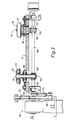
- Figure 2 is a partial plan view in the direction of arrow II of Figure 1;
- Figure 3 is a section view taken generally along the line III-III of Figure 2;
- Figure 4 is a partial side view taken generally in the direction of arrow IV of Figure 3;
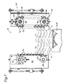
- Figure 5 is a view taken generally in the direction of the arrow V of Figure 1;
- Figure 6 is a view taken generally along the line VI-VI of Figure 5;
- Figure 7 is a view corresponding to Figure 5 but with parts thereof shown in their positions at a later stage in an operative cycle of the collator assembly;
- Figure 8 is an enlarged side view of some of the parts shown in Figure 1;
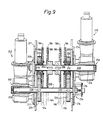
- Figure 9 is a sectional view generally along the line IX-IX of Figure 8;
- Figures 10a to 10j are diagrammatic representations of parts of an infeed means at progressive stages in a cycle of operation thereof; and,
- Figures 11 to 14 are diagrammatic representations of parts of the collator assembly of Figure 1 at progressive stages in a cycle of operation thereof.
- Difficulties met hitherto in forming stacks of cured concrete roof tiles free of incidental damage are overcome by the "no-load" or substantially "no-load" conditions exerted upon the cured concrete roof tiles by the novel collator assembly provided by the present invention.
- The collator assembly, which is designated 10 in Figure 1, generally comprises a primary infeed
device 20 for feeding concrete roof tiles T seriatim, a secondary infeeddevice 22 for arranging tiles fed thereto in a spaced array, astack forming means 24 including twosupports stack clamping device 30 for removing a stack of tiles T formed on said supports, and, a synchronising means (not shown) for ensuring the accurate sequencing of the various drive means for theassembly 10. - The
collator assembly 10 is supported in and on a floor mounted fabricatedmainframe 40, see Figure 1, and supported over a large portion of its length is the primary infeeddevice 20 which comprises an infeedpolycord conveyor 42 of conventional design. Thus theconveyor 42 comprises twin cords 46 which pass over associated pairs ofwheels mainframe 40, see Figure 1, it being appreciated that only one each of the pairs ofwheels - Downstream of said conveyor 44, the primary infeed
device 20 also comprises apolycord conveyor 54twin cords 56 of which pass over associated pairs ofwheels wheels 60 and 62 form part of a polycord tensioning means also of conventional design. All of the saidwheels subframe 70 of themainframe 40 as shown in Figure 1. - The primary infeed
device 20 also comprises velocity control means 72 located on asubframe 74 of themainframe 40 downstream of theconveyor 54 as shown in Figure 1. Themeans 72, see especially Figures 2, 3 and 4 comprises opposed pairs ofidler rolls rolls conveyors 44 and 54, are thereafter fed at a controlled rate to the secondary infeeddevice 22 as will be described more fully hereafter. The idler rolls 80,82,84 and 86 are mounted onsimple bearing blocks 96 adjustably mounted on saidsubframe 74, see Figures 2 and 4. - The driven
rolls spindles rolls 90, theirspindles 94 and the drive means 98 will now be particularly described with reference to Figures 2 and 3 with the like parts of the connection between therolls 88, theirspindles 90 and the drive means 97 being accorded like reference characters. - Thus, the
spindles 94, each of which is mounted in abearing 100 and extends through thesubframe 74, provide support for an associatedworm gear 102. Theworm gears 102 are arranged in meshing engagement withlike worm gears 104 provided on adrive shaft 106. Theshaft 106 extends beneath thesubframe 74, as shown in Figure 3, and has aleft hand end 108 thereof supported by abearing bracket 110 and aright hand end 112 therof supported by abearing bracket 114. - The
left hand end 108 of theshaft 106 is connected to the drive means 98 as shown in Figures 3 and 4, which drive means 98 is also connected to thesubframe 74 via torsion elements 124,126 connected between abracket 128 of said drive means 96 and abracket 130 secured to an underside of thesubframe 74 as shown in Figures 3 and 4. - For engaging with the tiles T, the opposite pairs of driven
rolls compression pads 131 extending for some 330° about the periphery of therolls pads 131 and thegaps 132 provided therein will be made clear hereinafter. - The secondary
infeed device 22, see Figures 5, 6 and 7 comprises a conventional fallingshelf conveyor 140 supported on asubframe 142 of themainframe 40, see Figure 1. Thus theconveyor 140 comprises opposed pairs of shelves 144,146 carried by associated pairs ofdrive chains - The
chains 148 are mounted on upper and lower sprockets, not shown, which are in turn mounted on drive and drivenshafts forward walls subframe 142, see Figures 5 and 6. - Likewise, the
chains 150 are mounted on upper andlower sprockets shafts forward wall subframe 142, see Figure 6. - The
drive shafts subframe 142 and connected to theshaft 156 causes, when thecollator assembly 10 is in use, downward movement of theshelves - The
stack forming means 24 is mounted between upper andlower subframes mainframe 40; see Figure 1. - The
means 24 comprises a first pair ofendless chains support 26, thechains upper sprockets - The means 24 also comprises a second pair of
endless chains support 28, thechains upper sprockets - As shown in Figure 9, the
sprockets drive shaft 208; however, thesprockets respective bearings shaft 208. - The
shaft 208, which is journalled at itsleft hand end 207 in bearing 209 secured to awall 211 of thesubframe 180, has aright hand end 213 thereof which extends through aside wall 214 of thesubframe 180, see Figure 9 to mesh with aspindle drive 216 of drive means 218. Thus, when thecollator assembly 10 is in use, the drive means 218 is effective through thesplined drive 216, theshaft 208, thekeyed sprockets chains support 26. - Also as shown in Figure 9, the
sprockets concentric gear wheels gear wheels drive shaft 232, see Figures 1, 8 and 9. - The
shaft 232, which is journalled at itsright hand end 234 in abearing 236 secured to theside wall 214 of thesubframe 180, has aleft hand end 238 thereof which extends through theside wall 211 of thesubframe 180, see Figure 9, to mesh with asplined drive 240 of drive means 242. Thus, when thecollator assembly 10 is in use the drive means 242 is effective through thesplined drive 240, theshaft 232, thekeyed gear wheels gear wheels sprockets chains support 28. - By the arrangement just described, when the
collator assembly 10 is in use, thesupports inoperative run 246 through which thesupports upstream end 248 of the operative run 244 as the other one thereof reaches adownstream end 262 of the operative run 244, see Figure 11. - The supports 26 and 28 of the
stack forming means 24 are each provided withroll elements bracket members 254, see especially Figures 1 and 6, there being twosuch rolls coincident axes - The
stack forming means 24 also comprises adjacent the operative run 244 herein defined,guide rails 260, only one of which is shown in chain dot lines in Figure 1, which rails 260 are engaged by therolls collator assembly 10 is in use. - The
stack forming means 24 further comprises pairs of upper and lowerstack guide elements guide elements lower subframes supports - The
stack clamping device 30 is of conventional design and will not be described herein in detail. Suffice to say that thedevice 30 is pivotally mounted on thesubframe 182 for movement between a loading position shown in ghost-line 30a in which clamps thereof straddle a stack of tiles T, and anunloading position 30b, see Figure 1. - When the
collator assembly 10 of the present invention is in use tiles T are fed seriation in spaced relationship or juxtaposed end to end along theconveyor 42 to theconveyor 54 and thus to the velocity control means 72. - A first tile T1 approaching the
means 72 is engaged by the opposed pairs of idler rolls 80 and 82 and then by the opposed pair of driven rolls 88. - As described herein the
rolls 88 are provided with gappedresilient pads 131 extending peripherally thereabout, and thegaps 132 in thepads 131, are positioned so that opposite leading edges of the tile T1 enter thegaps 132, see Figure 10a and 10b, thereby facilitating the interengagement between therolls 88 and the tile T1. - The
rolls 88 are driven at a higher peripheral speed than the linear of the tile T1 in order to accelerate the tile T1 away from a following tile T2, see Figures 10c, 10d, 10e and 10f. - As shown in Figures 10e and 10f, the opposite leading edges of the tile T1 approach and enter the
gaps 132 of the opposed driven rolls 90. Thus the tile T1 is spaced from the tile T2 whose opposite leading edges now approach and enter thegaps 132 of therolls 88 as shown in Figures 10g, 10h and 10i. - At this time the rate of progress of the tile T1 is being retarded by the opposed driven rolls 90, see Figures 10i and 10j where it is evident that the tile T2 is catching up with the tile T1; however, at this time the tile T1 has exited the velocity control means 72 and has been received on a pair of
shelves support - Successive tiles T1 to T40 are fed by the
conveyors means 22 in a spaced array. - As the successive tiles T1 to T40 are fed to the secondary infeed means 22, the drive means 172 is operated to cause the shelves 144,146 to be lowered to cause deposition of successive lowermost tiles of the spaced arrays onto the
support support support support support downstream end 262 of said operative run 244, see Figure 4. - When the stack of tiles is complete the
stack clamping device 30 is operated to secure the stack between clamp arms thereof in theposition 30a of Figure 1. Thereafter, theclamp 30 is pivoted anti-clockwise, viewing Figures 1 and 14, into aposition 30b in Figure 1 in which the stack of tiles T1 to T40 is released onto a packaging table or the like. - As the stack of tiles is completed on the
support downstream end 262 of the operative run 244, the other of the twosupports upstream end 248 of said operative run 244, i.e. thesupport - It is evident from the foregoing that the drive means 218 or 242 will be caused to operate at a rate commensurate with ensuring the passage of the
support downstream end 262 of said operative run 244, along theinoperative run 246 and about their respective sprocket 188,190 or 198,200 to bring thesupport upstream end 248 of the operative run 244 as the other of the two supports with a stack of tiles formed thereupon reaches the downstream end of said operative run. - The operation of the velocity control means 72 has been described in relation to feeding tiles seriation to the secondary infeed means 22; however, the
means 72 has a further operative mode which is effected after the delivery thereby of the 40th tile to the secondary infeed means 22 and as thesupport upstream end 248 of the operative run 244 of thestack forming means 24. - In its further operative mode, the rotational speeds of the
rolls shelves 144 of themeans 22 thereby to allow the downward passage of thesupport - It will also be evident that the operations of the various drive means of the collator assembly are closely synchronised in order to achieve the most advantageous use of the invention.
- Whereas the
collator assembly 10 and specifically thestack forming means 24 has been set up to form stacks containing 40 tiles, in other arrangements any requisite numbers of tiles may be formed into stacks. - Modifications which may be made within the scope of the present invention include a collator assembly in which the stack forming means has more than two supports on which stacks of tiles are formed, for example, in an arrangement where the stacks are of 10 tiles, there may be four supports arranged two each on associated pairs of the endless chains.
- It will be appreciated that the compact nature of the novel collator arrangement herein described may be utilised with established tile plant where space is at a premium.
Claims (10)
- A collator assembly comprising a stack forming means (24) for use in forming stacks of articles (T), said stack forming means (24) having a plurality of supports (26,28) on each of which, when the assembly is in use, successive stacks of articles (T) are formed, the assembly also comprising conveyor means (42) for feeding articles (T) seriatim to the stack-forming means (24), the assembly further comprising an infeed means (20,22) for feeding articles (T) from said conveyor means (42) to said stack forming means (24) wherein articles (T) are fed to the stack forming means (24) by the infeed means (20,22) under "no load" or "substantially no load" conditions characterised in that, the infeed means comprises primary and secondary infeed devices (20,22) the primary infeed device (20) comprising an infeed conveyor (54) and an article velocity control means (72) for controlling the speed at which an article approaches the secondary infeed device (22), the secondary infeed device comprising article supporting shelves (144,146) on which articles (T) are marshalled in a spaced array above the supports (26,28) for subsequent deposition onto one of the supports (26,28) or onto preceding articles (T) supported on one of said supports (26,28), wherein, when the assembly is in use, the supports (26,28) are moved by associated drive means (218,242) in turn through the same spacial path, the spacial path comprising an operative run (244) at an upstream end (248) of which, when the assembly is in use, articles (T) are fed seriatim to the stack forming means (24) to form a stack of such articles (T) on the supports (26,28) in turn, the spacial path also comprising an inoperative run (246) through which, when the assembly is in use, the supports (26,28), having successively had a stack of articles removed therefrom at a downstream end (262) of said operative run (244), are thereafter successively moved by the drive means (218,242) to return each support (26,28) to the upstream end (248) of the operative run (244) as a preceding support (26,28) having passed through said operative run (244), approaches the downstream end (262) thereof.
- An assembly according to Claim 1 characterised in that the velocity control means (72) comprises article engaging wheels (58,60,62,64,66) which, when the assembly is in use, grippingly engage the articles (T) fed thereto by the primary conveyor (54) to adjust the velocity of the articles (T) thereby reducing or eliminating any impact loads suffered by the articles (T) on reaching the secondary infeed device (22) of the assembly.
- An assembly according to Claim 1 characterised in that the drive means (218,242) comprises at least one endless carrier element for each of the supports (26,28) respectively.
- An assembly according to Claim 3 characterised in that the drive means (218,242) comprises two endless carrier elements (184,186,194,196) for each of the supports (26,28).
- An assembly according to either one of Claims 3 and 4 characterised in that the carrier elements associated with the supports (26,28) extends about associated driven (188,190,198,200) and idler wheels mounted in the assembly at or towards opposite ends of the operative and inoperative runs (244,246) respectively of the spacial path.
- An assembly according to Claim 5 characterised in that the driven and idler wheels at respective ends of the operative and inoperative runs (244,246) of the spacial path are arranged on coincident axes (208) or substantially so.
- An assembly according to either one of Claims 5 and 6 characterised in that the carrier elements are provided by endless chains (184,186,194,196) and the driven and idler wheels therefor by sprockets (188,190,198,200).
- An assembly according to any one of Claims 1 to 7 characterised in that means are provided for synchronising the operation of: a) the drive means for the infeed conveyor (54), b) the article velocity control means (72), c) the secondary infeed device (22), and d) the supports (26,28) whereby, when the assembly is in use and articles (T) are fed seriation by the infeed conveyor (54) to the article velocity control means (72), leading ones of said articles (T) may be temporarily estopped from approaching and entering said secondary infeed device (22) to enable a support (26,28) to be moved by its respective drive means along said spacial path and between the spaced array of article supporting shelves (144,146) thereby enabling said next-in-line support (26.28) to move successively into an operative position at an upstream end (248) of said operative run (244) of the spacial path.
- An assembly according to any one of Claims 1 to 8 characterised in that the stack forming means (24) comprises two supports (26,28) on each of which, in turn, when the assembly is in use, successive stacks of articles (T) are formed.
- An assembly according to any one of Claims 1 to 9 characterised in that the assembly is adapted for use in forming stacks of concrete roof tiles (T).
Priority Applications (1)
| Application Number | Priority Date | Filing Date | Title |
|---|---|---|---|
| SI9430103T SI0720580T1 (en) | 1993-09-25 | 1994-09-13 | Improvements in collation assemblies |
Applications Claiming Priority (3)
| Application Number | Priority Date | Filing Date | Title |
|---|---|---|---|
| GB9319854 | 1993-09-25 | ||
| GB9319854A GB2282117B (en) | 1993-09-25 | 1993-09-25 | Assembly for stacking articles |
| PCT/EP1994/003066 WO1995008501A1 (en) | 1993-09-25 | 1994-09-13 | Improvements in collation assemblies |
Publications (2)
| Publication Number | Publication Date |
|---|---|
| EP0720580A1 EP0720580A1 (en) | 1996-07-10 |
| EP0720580B1 true EP0720580B1 (en) | 1997-09-24 |
Family
ID=10742559
Family Applications (1)
| Application Number | Title | Priority Date | Filing Date |
|---|---|---|---|
| EP94928346A Expired - Lifetime EP0720580B1 (en) | 1993-09-25 | 1994-09-13 | Improvements in collation assemblies |
Country Status (23)
| Country | Link |
|---|---|
| US (1) | US5885055A (en) |
| EP (1) | EP0720580B1 (en) |
| JP (1) | JPH09503733A (en) |
| CN (1) | CN1044104C (en) |
| AT (1) | ATE158557T1 (en) |
| AU (1) | AU683499B2 (en) |
| BR (1) | BR9407603A (en) |
| CZ (1) | CZ87096A3 (en) |
| DE (1) | DE69405879T2 (en) |
| DK (1) | DK0720580T3 (en) |
| EE (1) | EE03210B1 (en) |
| ES (1) | ES2110783T3 (en) |
| FI (1) | FI961353A0 (en) |
| GB (1) | GB2282117B (en) |
| HU (1) | HUT74188A (en) |
| LV (1) | LV11537B (en) |
| MY (1) | MY111035A (en) |
| NO (1) | NO961187L (en) |
| NZ (1) | NZ273938A (en) |
| PL (1) | PL174302B1 (en) |
| RU (1) | RU2139828C1 (en) |
| SK (1) | SK39496A3 (en) |
| WO (1) | WO1995008501A1 (en) |
Families Citing this family (4)
| Publication number | Priority date | Publication date | Assignee | Title |
|---|---|---|---|---|
| EP2605342B8 (en) * | 2007-09-28 | 2017-06-28 | Kabushiki Kaisha Toshiba | Power supply connector |
| US9637259B2 (en) * | 2015-04-27 | 2017-05-02 | Khs Gmbh | Racetrack collator, carriage and related methods |
| CN106276191B (en) * | 2016-11-18 | 2019-05-03 | 山东爱而生智能科技有限公司 | A size-adjustable sorting mechanism |
| CN108995876B (en) * | 2017-10-23 | 2023-06-09 | 青岛海科佳智能科技股份有限公司 | Flour conveying and sorting device |
Family Cites Families (11)
| Publication number | Priority date | Publication date | Assignee | Title |
|---|---|---|---|---|
| AT215900B (en) * | 1959-05-21 | 1961-06-26 | Bonnierfoeretagen Ab | Device for storing newspapers or the like in the form of bumps |
| US3921826A (en) * | 1973-05-25 | 1975-11-25 | Howard Gene Rice | Tray stacking system |
| DE2532410A1 (en) * | 1975-07-19 | 1977-02-03 | Stierlen Maquet Ag | Food tray stacking mechanism - works vertically with paternoster type conveyor in conjunction with horizontal feed conveyor |
| CH605354A5 (en) * | 1976-11-15 | 1978-09-29 | Bogatzki Hans Ulrich | |
| CH630041A5 (en) * | 1978-04-28 | 1982-05-28 | Grapha Holding Ag | Device for forming paper sheet stacks from partial stacks |
| DE3017612A1 (en) * | 1980-05-08 | 1981-11-12 | Ing. Kurt Schade Formen- + Werkzeugbau, 2878 Wildeshausen | Pantile stacking and transfer unit - has outwardly open hods moving down in steps along outwardly inclined guides on indexing turntable |
| IT1136965B (en) * | 1981-03-27 | 1986-09-03 | Angelo Bartesaghi | DEVICE FOR THE COLLECTION IN PACKAGES OF ESSENTIAL LEAF ELEMENTS |
| GB8417249D0 (en) * | 1984-07-06 | 1984-08-08 | Redland Roof Tiles Ltd | Collation assemblies |
| GB8627657D0 (en) * | 1986-11-19 | 1986-12-17 | Redland Roof Tiles Ltd | Collation assemblies |
| DE3736868A1 (en) * | 1987-10-30 | 1989-05-11 | Benz & Hilgers Gmbh | Stacking apparatus on packaging machines for bags or the like |
| DD287010A5 (en) * | 1989-08-01 | 1991-02-14 | Veb Polygraph Buchbindereimaschinenweke,De | DEVICE FOR STACKING EDGED FORMS |
-
1993
- 1993-09-25 GB GB9319854A patent/GB2282117B/en not_active Revoked
-
1994
- 1994-09-13 AT AT94928346T patent/ATE158557T1/en not_active IP Right Cessation
- 1994-09-13 WO PCT/EP1994/003066 patent/WO1995008501A1/en not_active Ceased
- 1994-09-13 HU HU9600673A patent/HUT74188A/en unknown
- 1994-09-13 US US08/605,139 patent/US5885055A/en not_active Expired - Fee Related
- 1994-09-13 CZ CZ96870A patent/CZ87096A3/en unknown
- 1994-09-13 ES ES94928346T patent/ES2110783T3/en not_active Expired - Lifetime
- 1994-09-13 BR BR9407603A patent/BR9407603A/en not_active IP Right Cessation
- 1994-09-13 JP JP7509539A patent/JPH09503733A/en active Pending
- 1994-09-13 EP EP94928346A patent/EP0720580B1/en not_active Expired - Lifetime
- 1994-09-13 AU AU77820/94A patent/AU683499B2/en not_active Ceased
- 1994-09-13 NZ NZ273938A patent/NZ273938A/en unknown
- 1994-09-13 SK SK394-96A patent/SK39496A3/en unknown
- 1994-09-13 DK DK94928346.9T patent/DK0720580T3/en active
- 1994-09-13 DE DE69405879T patent/DE69405879T2/en not_active Expired - Fee Related
- 1994-09-13 CN CN94193529A patent/CN1044104C/en not_active Expired - Fee Related
- 1994-09-13 PL PL94313618A patent/PL174302B1/en unknown
- 1994-09-13 RU RU96108245A patent/RU2139828C1/en active
- 1994-09-13 EE EE9600039A patent/EE03210B1/en unknown
- 1994-09-22 MY MYPI94002524A patent/MY111035A/en unknown
-
1996
- 1996-03-22 NO NO961187A patent/NO961187L/en not_active Application Discontinuation
- 1996-03-25 FI FI961353A patent/FI961353A0/en unknown
- 1996-04-17 LV LVP-96-119A patent/LV11537B/en unknown
Also Published As
| Publication number | Publication date |
|---|---|
| RU2139828C1 (en) | 1999-10-20 |
| CN1044104C (en) | 1999-07-14 |
| DE69405879D1 (en) | 1997-10-30 |
| DK0720580T3 (en) | 1998-05-11 |
| US5885055A (en) | 1999-03-23 |
| GB9319854D0 (en) | 1993-11-10 |
| JPH09503733A (en) | 1997-04-15 |
| CZ87096A3 (en) | 1997-07-16 |
| WO1995008501A1 (en) | 1995-03-30 |
| AU7782094A (en) | 1995-04-10 |
| PL174302B1 (en) | 1998-07-31 |
| GB2282117B (en) | 1997-04-16 |
| HU9600673D0 (en) | 1996-05-28 |
| FI961353A7 (en) | 1996-03-25 |
| LV11537A (en) | 1996-10-20 |
| EP0720580A1 (en) | 1996-07-10 |
| DE69405879T2 (en) | 1998-04-02 |
| ES2110783T3 (en) | 1998-02-16 |
| SK39496A3 (en) | 1996-10-02 |
| BR9407603A (en) | 1997-01-14 |
| NO961187D0 (en) | 1996-03-22 |
| AU683499B2 (en) | 1997-11-13 |
| MY111035A (en) | 1999-07-31 |
| PL313618A1 (en) | 1996-07-08 |
| NZ273938A (en) | 1998-01-26 |
| FI961353A0 (en) | 1996-03-25 |
| EE03210B1 (en) | 1999-08-16 |
| LV11537B (en) | 1996-12-20 |
| NO961187L (en) | 1996-03-22 |
| ATE158557T1 (en) | 1997-10-15 |
| HUT74188A (en) | 1996-11-28 |
| GB2282117A (en) | 1995-03-29 |
| CN1131935A (en) | 1996-09-25 |
Similar Documents
| Publication | Publication Date | Title |
|---|---|---|
| US3954190A (en) | Palletizer | |
| US4569620A (en) | Book turn-around and stack accumulator apparatus | |
| CA1203783A (en) | Packaging apparatus for stick confections | |
| US3713650A (en) | Stacking of sheets | |
| JP3643847B2 (en) | Method and apparatus for reversing sheet-like member | |
| US4712361A (en) | Collation assemblies | |
| US5885055A (en) | Collation assemblies | |
| US3664520A (en) | Handling and transferring device for plane objects, particularly glass sheets | |
| US4073387A (en) | Method and apparatus for tier forming on a row by row basis | |
| US2890675A (en) | Core handling machine | |
| US3019925A (en) | Block handling apparatus | |
| US3241689A (en) | Article handling apparatus | |
| JP3759202B2 (en) | Sheet member conveying method and apparatus | |
| JPS5824332B2 (en) | Automatic alignment and supply method of articles | |
| US4360101A (en) | Case feed control for article handling apparatus | |
| US3592328A (en) | Transfer and orienting mechanism for articles | |
| GB2161128A (en) | Improvements in deracking assemblies | |
| JP3355769B2 (en) | Conveyor device | |
| JPS6313896B2 (en) | ||
| JPH058261Y2 (en) | ||
| EP0170437A1 (en) | Improvements in tile manufacturing apparatus | |
| CA1041563A (en) | Downwardly -indexing-elevator type stacker with accumulation zone tier arranging and depositors | |
| JPH0729714B2 (en) | Rubber sheet stacking machine | |
| JPS55106929A (en) | Conveying system for articles | |
| JPH0524662Y2 (en) |
Legal Events
| Date | Code | Title | Description |
|---|---|---|---|
| PUAI | Public reference made under article 153(3) epc to a published international application that has entered the european phase |
Free format text: ORIGINAL CODE: 0009012 |
|
| 17P | Request for examination filed |
Effective date: 19960322 |
|
| AK | Designated contracting states |
Kind code of ref document: A1 Designated state(s): AT BE DE DK ES FR GB IE IT NL PT SE |
|
| AX | Request for extension of the european patent |
Free format text: LT PAYMENT 960322;SI PAYMENT 960322 |
|
| RAX | Requested extension states of the european patent have changed |
Free format text: LT PAYMENT 960322;SI PAYMENT 960322 |
|
| 17Q | First examination report despatched |
Effective date: 19960627 |
|
| GRAG | Despatch of communication of intention to grant |
Free format text: ORIGINAL CODE: EPIDOS AGRA |
|
| GRAH | Despatch of communication of intention to grant a patent |
Free format text: ORIGINAL CODE: EPIDOS IGRA |
|
| GRAH | Despatch of communication of intention to grant a patent |
Free format text: ORIGINAL CODE: EPIDOS IGRA |
|
| GRAA | (expected) grant |
Free format text: ORIGINAL CODE: 0009210 |
|
| AK | Designated contracting states |
Kind code of ref document: B1 Designated state(s): AT BE DE DK ES FR GB IE IT NL PT SE |
|
| AX | Request for extension of the european patent |
Free format text: LT PAYMENT 960322;SI PAYMENT 960322 |
|
| REF | Corresponds to: |
Ref document number: 158557 Country of ref document: AT Date of ref document: 19971015 Kind code of ref document: T |
|
| REF | Corresponds to: |
Ref document number: 69405879 Country of ref document: DE Date of ref document: 19971030 |
|
| ITF | It: translation for a ep patent filed | ||
| REG | Reference to a national code |
Ref country code: IE Ref legal event code: FG4D Free format text: 76702 |
|
| ET | Fr: translation filed | ||
| REG | Reference to a national code |
Ref country code: ES Ref legal event code: FG2A Ref document number: 2110783 Country of ref document: ES Kind code of ref document: T3 |
|
| REG | Reference to a national code |
Ref country code: PT Ref legal event code: SC4A Free format text: AVAILABILITY OF NATIONAL TRANSLATION Effective date: 19971222 |
|
| REG | Reference to a national code |
Ref country code: DK Ref legal event code: T3 |
|
| PGFP | Annual fee paid to national office [announced via postgrant information from national office to epo] |
Ref country code: IE Payment date: 19980710 Year of fee payment: 5 |
|
| PLBE | No opposition filed within time limit |
Free format text: ORIGINAL CODE: 0009261 |
|
| STAA | Information on the status of an ep patent application or granted ep patent |
Free format text: STATUS: NO OPPOSITION FILED WITHIN TIME LIMIT |
|
| 26N | No opposition filed | ||
| PGFP | Annual fee paid to national office [announced via postgrant information from national office to epo] |
Ref country code: GB Payment date: 19990813 Year of fee payment: 6 |
|
| PGFP | Annual fee paid to national office [announced via postgrant information from national office to epo] |
Ref country code: PT Payment date: 19990818 Year of fee payment: 6 |
|
| PG25 | Lapsed in a contracting state [announced via postgrant information from national office to epo] |
Ref country code: IE Free format text: LAPSE BECAUSE OF NON-PAYMENT OF DUE FEES Effective date: 19990913 |
|
| PGFP | Annual fee paid to national office [announced via postgrant information from national office to epo] |
Ref country code: SE Payment date: 19990915 Year of fee payment: 6 Ref country code: AT Payment date: 19990915 Year of fee payment: 6 |
|
| PGFP | Annual fee paid to national office [announced via postgrant information from national office to epo] |
Ref country code: NL Payment date: 19990916 Year of fee payment: 6 |
|
| PGFP | Annual fee paid to national office [announced via postgrant information from national office to epo] |
Ref country code: FR Payment date: 19990917 Year of fee payment: 6 Ref country code: DK Payment date: 19990917 Year of fee payment: 6 Ref country code: DE Payment date: 19990917 Year of fee payment: 6 |
|
| PGFP | Annual fee paid to national office [announced via postgrant information from national office to epo] |
Ref country code: ES Payment date: 19990922 Year of fee payment: 6 Ref country code: BE Payment date: 19990922 Year of fee payment: 6 |
|
| PG25 | Lapsed in a contracting state [announced via postgrant information from national office to epo] |
Ref country code: GB Free format text: LAPSE BECAUSE OF NON-PAYMENT OF DUE FEES Effective date: 20000913 Ref country code: DK Free format text: LAPSE BECAUSE OF NON-PAYMENT OF DUE FEES Effective date: 20000913 Ref country code: AT Free format text: LAPSE BECAUSE OF NON-PAYMENT OF DUE FEES Effective date: 20000913 |
|
| PG25 | Lapsed in a contracting state [announced via postgrant information from national office to epo] |
Ref country code: SE Free format text: THE PATENT HAS BEEN ANNULLED BY A DECISION OF A NATIONAL AUTHORITY Effective date: 20000914 Ref country code: ES Free format text: LAPSE BECAUSE OF NON-PAYMENT OF DUE FEES Effective date: 20000914 |
|
| REG | Reference to a national code |
Ref country code: IE Ref legal event code: MM4A |
|
| PG25 | Lapsed in a contracting state [announced via postgrant information from national office to epo] |
Ref country code: BE Free format text: LAPSE BECAUSE OF NON-PAYMENT OF DUE FEES Effective date: 20000930 |
|
| BERE | Be: lapsed |
Owner name: REDLAND TECHNOLOGIES LTD Effective date: 20000930 |
|
| PG25 | Lapsed in a contracting state [announced via postgrant information from national office to epo] |
Ref country code: PT Free format text: LAPSE BECAUSE OF NON-PAYMENT OF DUE FEES Effective date: 20010331 |
|
| PG25 | Lapsed in a contracting state [announced via postgrant information from national office to epo] |
Ref country code: NL Free format text: LAPSE BECAUSE OF NON-PAYMENT OF DUE FEES Effective date: 20010401 |
|
| GBPC | Gb: european patent ceased through non-payment of renewal fee |
Effective date: 20000913 |
|
| EUG | Se: european patent has lapsed |
Ref document number: 94928346.9 |
|
| REG | Reference to a national code |
Ref country code: DK Ref legal event code: EBP |
|
| PG25 | Lapsed in a contracting state [announced via postgrant information from national office to epo] |
Ref country code: FR Free format text: LAPSE BECAUSE OF NON-PAYMENT OF DUE FEES Effective date: 20010531 |
|
| NLV4 | Nl: lapsed or anulled due to non-payment of the annual fee |
Effective date: 20010401 |
|
| PG25 | Lapsed in a contracting state [announced via postgrant information from national office to epo] |
Ref country code: DE Free format text: LAPSE BECAUSE OF NON-PAYMENT OF DUE FEES Effective date: 20010601 |
|
| REG | Reference to a national code |
Ref country code: FR Ref legal event code: ST |
|
| REG | Reference to a national code |
Ref country code: PT Ref legal event code: MM4A Free format text: LAPSE DUE TO NON-PAYMENT OF FEES Effective date: 20010331 |
|
| REG | Reference to a national code |
Ref country code: ES Ref legal event code: FD2A Effective date: 20011011 |
|
| PG25 | Lapsed in a contracting state [announced via postgrant information from national office to epo] |
Ref country code: IT Free format text: LAPSE BECAUSE OF NON-PAYMENT OF DUE FEES Effective date: 20050913 |