EP0720524B1 - Zerkleinerungsvorrichtung mit scherwirkung - Google Patents
Zerkleinerungsvorrichtung mit scherwirkung Download PDFInfo
- Publication number
- EP0720524B1 EP0720524B1 EP19930918856 EP93918856A EP0720524B1 EP 0720524 B1 EP0720524 B1 EP 0720524B1 EP 19930918856 EP19930918856 EP 19930918856 EP 93918856 A EP93918856 A EP 93918856A EP 0720524 B1 EP0720524 B1 EP 0720524B1
- Authority
- EP
- European Patent Office
- Prior art keywords
- tines
- rotor
- stator
- rows
- housing
- Prior art date
- Legal status (The legal status is an assumption and is not a legal conclusion. Google has not performed a legal analysis and makes no representation as to the accuracy of the status listed.)
- Expired - Lifetime
Links
- 230000009471 action Effects 0.000 title claims description 7
- 238000010008 shearing Methods 0.000 title claims description 7
- 239000000463 material Substances 0.000 claims abstract description 32
- 239000012634 fragment Substances 0.000 description 6
- 238000004064 recycling Methods 0.000 description 6
- 229910000831 Steel Inorganic materials 0.000 description 5
- 238000000034 method Methods 0.000 description 5
- 230000008569 process Effects 0.000 description 5
- 239000010959 steel Substances 0.000 description 5
- 229920001971 elastomer Polymers 0.000 description 4
- 239000005060 rubber Substances 0.000 description 4
- 239000004636 vulcanized rubber Substances 0.000 description 3
- VYPSYNLAJGMNEJ-UHFFFAOYSA-N Silicium dioxide Chemical compound O=[Si]=O VYPSYNLAJGMNEJ-UHFFFAOYSA-N 0.000 description 2
- 238000004140 cleaning Methods 0.000 description 2
- 150000001875 compounds Chemical class 0.000 description 2
- 239000000470 constituent Substances 0.000 description 2
- 238000010276 construction Methods 0.000 description 2
- 230000007613 environmental effect Effects 0.000 description 2
- 239000000383 hazardous chemical Substances 0.000 description 2
- 231100000206 health hazard Toxicity 0.000 description 2
- 238000012423 maintenance Methods 0.000 description 2
- 230000007246 mechanism Effects 0.000 description 2
- 239000004033 plastic Substances 0.000 description 2
- 238000012545 processing Methods 0.000 description 2
- 239000002023 wood Substances 0.000 description 2
- 239000004215 Carbon black (E152) Substances 0.000 description 1
- 229910000760 Hardened steel Inorganic materials 0.000 description 1
- 239000005864 Sulphur Substances 0.000 description 1
- 150000004982 aromatic amines Chemical class 0.000 description 1
- 239000010425 asbestos Substances 0.000 description 1
- 235000013405 beer Nutrition 0.000 description 1
- 230000000711 cancerogenic effect Effects 0.000 description 1
- 230000000295 complement effect Effects 0.000 description 1
- 238000004132 cross linking Methods 0.000 description 1
- 238000005520 cutting process Methods 0.000 description 1
- 230000006378 damage Effects 0.000 description 1
- 239000012530 fluid Substances 0.000 description 1
- 239000011521 glass Substances 0.000 description 1
- 239000010440 gypsum Substances 0.000 description 1
- 229910052602 gypsum Inorganic materials 0.000 description 1
- 230000005802 health problem Effects 0.000 description 1
- 229930195733 hydrocarbon Natural products 0.000 description 1
- 150000002430 hydrocarbons Chemical class 0.000 description 1
- 238000004519 manufacturing process Methods 0.000 description 1
- 238000002844 melting Methods 0.000 description 1
- 230000008018 melting Effects 0.000 description 1
- QSHDDOUJBYECFT-UHFFFAOYSA-N mercury Chemical compound [Hg] QSHDDOUJBYECFT-UHFFFAOYSA-N 0.000 description 1
- 229910052753 mercury Inorganic materials 0.000 description 1
- 239000002184 metal Substances 0.000 description 1
- 229910052751 metal Inorganic materials 0.000 description 1
- 231100000219 mutagenic Toxicity 0.000 description 1
- 230000003505 mutagenic effect Effects 0.000 description 1
- 229920003052 natural elastomer Polymers 0.000 description 1
- 229920001194 natural rubber Polymers 0.000 description 1
- 239000003921 oil Substances 0.000 description 1
- 239000003973 paint Substances 0.000 description 1
- 239000000123 paper Substances 0.000 description 1
- 239000012188 paraffin wax Substances 0.000 description 1
- 230000000737 periodic effect Effects 0.000 description 1
- 150000002989 phenols Chemical class 0.000 description 1
- 230000002250 progressing effect Effects 0.000 description 1
- 239000002994 raw material Substances 0.000 description 1
- 238000011084 recovery Methods 0.000 description 1
- 230000009467 reduction Effects 0.000 description 1
- 238000011160 research Methods 0.000 description 1
- 229910052895 riebeckite Inorganic materials 0.000 description 1
- 239000000377 silicon dioxide Substances 0.000 description 1
- 238000003860 storage Methods 0.000 description 1
- 239000000126 substance Substances 0.000 description 1
- 229920003051 synthetic elastomer Polymers 0.000 description 1
- 239000005061 synthetic rubber Substances 0.000 description 1
- 239000011269 tar Substances 0.000 description 1
- 230000036346 tooth eruption Effects 0.000 description 1
- 239000010913 used oil Substances 0.000 description 1
- 238000004073 vulcanization Methods 0.000 description 1
- 239000002699 waste material Substances 0.000 description 1
Images


Classifications
-
- B—PERFORMING OPERATIONS; TRANSPORTING
- B29—WORKING OF PLASTICS; WORKING OF SUBSTANCES IN A PLASTIC STATE IN GENERAL
- B29B—PREPARATION OR PRETREATMENT OF THE MATERIAL TO BE SHAPED; MAKING GRANULES OR PREFORMS; RECOVERY OF PLASTICS OR OTHER CONSTITUENTS OF WASTE MATERIAL CONTAINING PLASTICS
- B29B17/00—Recovery of plastics or other constituents of waste material containing plastics
- B29B17/04—Disintegrating plastics, e.g. by milling
-
- B—PERFORMING OPERATIONS; TRANSPORTING
- B02—CRUSHING, PULVERISING, OR DISINTEGRATING; PREPARATORY TREATMENT OF GRAIN FOR MILLING
- B02C—CRUSHING, PULVERISING, OR DISINTEGRATING IN GENERAL; MILLING GRAIN
- B02C18/00—Disintegrating by knives or other cutting or tearing members which chop material into fragments
- B02C18/06—Disintegrating by knives or other cutting or tearing members which chop material into fragments with rotating knives
- B02C18/14—Disintegrating by knives or other cutting or tearing members which chop material into fragments with rotating knives within horizontal containers
- B02C18/145—Disintegrating by knives or other cutting or tearing members which chop material into fragments with rotating knives within horizontal containers with knives spaced axially and circumferentially on the periphery of a cylindrical rotor unit
-
- B—PERFORMING OPERATIONS; TRANSPORTING
- B29—WORKING OF PLASTICS; WORKING OF SUBSTANCES IN A PLASTIC STATE IN GENERAL
- B29L—INDEXING SCHEME ASSOCIATED WITH SUBCLASS B29C, RELATING TO PARTICULAR ARTICLES
- B29L2030/00—Pneumatic or solid tyres or parts thereof
-
- Y—GENERAL TAGGING OF NEW TECHNOLOGICAL DEVELOPMENTS; GENERAL TAGGING OF CROSS-SECTIONAL TECHNOLOGIES SPANNING OVER SEVERAL SECTIONS OF THE IPC; TECHNICAL SUBJECTS COVERED BY FORMER USPC CROSS-REFERENCE ART COLLECTIONS [XRACs] AND DIGESTS
- Y02—TECHNOLOGIES OR APPLICATIONS FOR MITIGATION OR ADAPTATION AGAINST CLIMATE CHANGE
- Y02W—CLIMATE CHANGE MITIGATION TECHNOLOGIES RELATED TO WASTEWATER TREATMENT OR WASTE MANAGEMENT
- Y02W30/00—Technologies for solid waste management
- Y02W30/50—Reuse, recycling or recovery technologies
- Y02W30/62—Plastics recycling; Rubber recycling
Definitions
- This invention relates to an apparatus for shredding materials, in recycling operations for example, and more particularly to a shredding apparatus in which rows of rotor tines pass through rows of stator tines to shear the materials.
- An initial step in such recycling involves reducing such materials to a basic form in which they can be more easily handled, usually through a process such as melting or shredding.
- Used tires for example, are presently increasingly being recycled, and the shredding of such tires into tiny fragments is a first step in such recycling.
- the storage of used tires in piles presents both a fire hazard and a health hazard.
- Burning of used tires releases into the atmosphere various substances mixed into the constituent rubber during its production and vulcanization, including compounds such as tars, silica, paraffin, aromatic amines or phenol derivatives, asbestos, accelerator compounds, etc., which are known or hypothesized to have mutagenic and carcinogenic properties.
- laws have been enacted or proposed requiring the safe destruction of used tires to avoid such environmental and health hazards.
- shredding of used tires obviates the need for new expenditures on energy and long-chain hydrocarbon resources, such as natural and synthetic rubbers.
- the extraordinary elastic properties and resistance to wear of vulcanized rubber due to the cross-linking of rubber molecules by "sulphur bridges" has caused vulcanized rubber to be used as a raw material for a vast range of products. There is consequently a large market for vulcanized rubber fragments generated by shredding of used tires.
- shredding is used as a first step in the recycling of waste plastic.
- recovery of oil, metal, paper and rubber from used oil filters is on the verge of becoming a major industry.
- garbage volume in a landfill site may be reduced by first putting the garbage through a shredding process.
- Prior art shredding devices are generally designed to shred material fed between cutters by tearing the material apart. Significant expenditures of energy are required to drive such machines.
- the apparatus should be fully enclosed and transportable.
- shredding apparatus In the prior art, many shredding devices utilize a tearing action, which expends a great deal of energy.
- shearing is the primary shredding mechanism, which reduces the energy expenditure.
- the subject apparatus also reduces materials to pieces of roughly uniform size, thereby simplifying and making more economical further processing of those pieces, which in turn increases their utility.
- Another desirable attribute of the subject apparatus is its relatively light weight in comparison to other shredding devices, and hence its increased portability relative to most prior art shredding devices.
- the fact that the apparatus is preferably fully enclosed in an external housing further facilitates transportation.
- the invention is a shredding apparatus comprising a rotor mounted to rotate between a pair of side walls, a housing extending in an arc on one side of the rotor between the pair of side walls, an inlet means for feeding material into an entry opening between the rotor and the housing, and a motor for rotating the rotor relative to the housing.
- the rotor has tines projecting generally radially outwardly therefrom in a series of rows equiangularly positioned around it. Each of those rows extends generally parallel to the axis of rotation.
- Each rotor tine has a generally flat face in the direction of rotation, those flat faces on tines in the same row extending generally in the same plane.
- the housing has stator tines projecting generally radially inwardly therefrom in a series of rows extending generally parallel to the axis of rotation;
- the stator tines are positioned such that one or more of the rotor tines pass between adjacent stator tines.
- Each stator tine has a generally flat face in the direction adapted to oppose the flat face on passing rotor tines.
- the flat faces on stator tines in the same row extend generally in the same plane.
- Each of the rotor tines and stator tines have a length substantially equal to the radial distance between facing surfaces on the rotor and the housing.
- Each of the rotor tines and stator tines is of substantially equal width, and the clearance between passing rotor and stator tines is quite small, such as approximately 3 mm (1/8 of an inch) for most applications. The clearance could be smaller in some cases, or larger in others, especially larger machines.
- the motor rotates the rotor relative to the housing at a speed of at least 500 rotations per minute.
- the rotor tines and stator tines are oriented such that the flat faces on one or both are angled slightly away from the radial direction such that the outer ends of the rotor tines pass the stator tines before the inner ends of the rotor tines. A small angle is thereby defined between the flat faces on the rotor tines and the flat faces on the stator tines as those tines pass.
- the small angle is preferably in the range of 5 to 20 degrees.
- the rotor tines and stator tines may be approximately 25 mm (1 inch) wide, and pass each other at a clearance of approximately 3 mm (1/8 of an inch).
- the flat faces on the rotor tines and stator tines may be replaceably mounted on the rotor and housing, respectively.
- stator tines There may be three rows of rotor tines spaced 120 degrees apart, and three rows of stator tines.
- the rotor tines pass the first row of stator tines before passing the second row of stator tines before passing the third row of stator tines.
- the tines in the first and second rows of stator tines are arranged longitudinally on the housing in pairs that are spaced from each other by the spacing of a missing pair.
- Each pair of stator tines in the first and second rows correspond in longitudinal position to a missing pair in the second and first rows respectively.
- the third row of stator tines and the three rows of rotor tines each have tines with longitudinal positions corresponding to the tines in both the first and second rows of stator tines.
- the housing preferably is movable relative to the rotor to increase the distance between facing surfaces on the rotor and the housing for facilitating maintenance and cleaning of the apparatus, and particularly for facilitating clearance of any jams.
- the invention is a shredder assembly that comprises a first shredding apparatus and a second substantially-smaller shredding apparatus.
- the inlet means of the second shredding apparatus is adapted to receive material output from the first shredding apparatus.
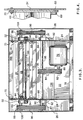
- the preferred embodiment of the shredding apparatus has a front wall 20, a back wall 22, a pair of inner side walls 24, and a pair of outer side walls 26.
- Each of the outer side walls 26 is mounted on a set of hinges 28.
- a rotor generally designated 30 is mounted on a pair of bearings 32, each of which is supported on a respective section of square tubing 34 secured to one of the inner side walls 24.
- Three rows of rotor tines 36 each extend across rotor 30, each of the three rows being angularly displaced 120 degrees from the other two rows.
- Each rotor tine 36 has a flat front face in the direction of rotation of rotor 30, a flat top face, and a flat sloping back face. The spacing between adjacent rotor tines 36 is slightly greater than the width of a tine 36.
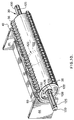
- a housing generally designated 40 and separately illustrated in Figure 7 has an arc member 42, each end of which is connected to a side member 44.
- a square tubing section 46 extends between the side members 44, and a plate 48 connects side members 44, tubing section 46 and arc member 42.
- arc member 42 In its operative position, as illustrated in Figures 2 and 5, arc member 42 extends concentrically around the axis of rotation of rotor 30.
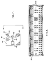
- Three rows of stator tines 50 each extend across arc member 42, as illustrated in Figures 8 and 9. Tines 50 in the first and second rows are arranged longitudinally on the inner surface of arc member 42 in pairs that are spaced from each other by the spacing of a missing pair.
- Each pair of tines 50 in the first and second rows correspond in longitudinal position on arc member 42 with a missing pair of tines 50 in the second and first rows, respectively.
- the tines 50 in the third row on arc member 42 are longitudinally positioned so as to correspond with the tines 50 in both the first and second rows.
- the longitudinal position of the stator tines 50 on arc member 42 are staggered from the longitudinal position of the rotor tines 36 on rotor 30, allowing the rotor tines to pass the stator tines with a slight clearance.
- the stator tines have a similar shape to the shape previously described for rotor tines.
- the height of the rotor and stator tines is such that when housing 40 is in its operative position, the end of the rotor tines have a slight clearance from the inner surface of arc member 42, and the end of the stator tines have a slight clearance from the surface of rotor 30, a typical clearance in each case being about 3 mm (1/8 of an inch).
- Material entering the shredding apparatus is pressed by the rotor tines 36 against the first and second rows of stator tines 50 having the tine spacing earlier described.
- the material is shredded into fragments of a small size by those two rows.
- the resulting fragments are then pressed against the third row of stator tines 50; the number of tines in that third row equals the number of tines in each row of rotor 30.
- the material is shredded by the third row of stator tines into fragments of still smaller size.
- each rotor tine 36 is set at a slight angle relative to the flat opposing face on each stator tine 50.
- the outer end of each tine 36 thereby passes the opposing face on a tine 50 before the inner end of tine 36 passes that face, and a scissors-like shearing action results.
- the width of a rotor tine 36 is approximately the same as the width of a stator tine 50, and the clearance between those sets of tines as they pass is quite small in relation to the tine width. With a tine width of 25 mm (1 inch), the clearance is approximately 3 mm (1/8 of an inch) in the preferred embodiment, although other small clearances could obviously be used, the acceptable range depending somewhat on the materials being shredded, keeping in mind that shearing is the desired mechanism.
- a scissors-like shearing action thereby commences as a rotor tine passes a stator tine, the action starting at the outer end of the rotor tine and progressing inwardly.
- Housing 40 can be shifted from the operative position shown in Figures 2 and 5 to a retracted position allowing cleaning or maintenance, shown in Figure 6, and especially facilitating the clearance of jams. This is accomplished by means of a hydraulic cylinder 54 that drives a piston 56 which is pivotally connected by a collar 57 to one end of an arm 58. The other end of arm 58 is fixed to a central position on a bar 60. Each end of bar 60 is rotatably mounted on a respective one of the inner side walls 24. One end of a pair of arms 62 is fixed to a respective one of the ends of bar 60. The other end of each arm 62 is slotted to receive a pin 64 that extends between a pair of brackets 66 connected to rectangular tubing section 46.
- each side member 44 of housing 40 slides in a recess defined by a lower bracket 68, a lateral guide member 69 secured to lower bracket 68, and an upper bracket 70. Movement of piston 56 out of cylinder 54 results in housing 40 moving from its operative position to the retracted position.
- the sequence of operation on startup, or after a stoppage due to a jam is that hydraulic fluid is pumped to hydraulic cylinder 54 by an electric motor (not shown) that is activated automatically each time electric motor 76 is switched on, so that the housing 40 moves from its operative position.
- the rotor 30 then starts to turn, which clears away any jammed material or any material left in the apparatus from a previous shutdown.
- the housing is then returned to its operative position, at which time shredding operations may be recommenced.
- An electrical motor 76 of approximately 110 kW (150 horsepower) is fastened to the base 78 of the shredding apparatus.
- the rotor 80 of motor 76 has a four-belt pulley 82 mounted on it.
- Four belts 84 extend around both that pulley and a four-belt pulley 86 on a driven shaft 88.
- Shaft 88 is mounted in a pair of bearings 90 that are each supported on an inner side wall 24 by a bracket 92.
- Each end of shaft 88 has a four-belt pulley 94 mounted on it, and tour belts 96 extends around both that pulley and a four-belt pulley 98 mounted on the axle 100 of rotor 30.
- the motor 76 is capable of rotating rotor 30 at typical speeds of from 500 r.p.m. to over 3,000 r.p.m., the optimum rotational speed is a function of the material being shredded, and is best determined through routine experimentation.
- feed channel 104 The material to be shredded is fed to the shredding apparatus through a broad feed channel generally designated 104, illustrated in profile in Figure 2.
- a portion of feed channel 104 is an input chute, defined by opposing inclined surfaces 106 and 108 and by opposing parallel surfaces 110, and mounted in a top wall 111 of the apparatus.
- An output chute is defined by opposing inclined surfaces 112 and 114 and by opposing parallel surfaces 116.
- rotor 30 has a steel axle 100 of 6.35 cm (2.5-inch) diameter, three steel disks 120 of 25 mm (1-inch) thickness and 30.5 cm (12-inch) diameter, and a circular cylindrical steel tube 122 of 25 mm (1-inch) thickness and 30.5 cm (12-inch) inside diameter.
- Each of the disks 120 is welded circumferentially to steel tube 122, one disk proximate each end and one centrally.
- a disk 124 of 15 cm (6-inch) diameter is circumferentially welded to the outside of each of the end-positioned disks 120 to extend concentric with the respective disk.
- Each end of axle 100 has a spline 125 that is 15 cm (6 inches) long and approximately 1.27 cm (0.5 inches) square.
- a spline 126 of similar cross-section extends in each of the end-positioned disks 120 and 124, and a key 128 is fitted between splines 125 and 126 to prevent relative rotation between axle 100 and disks 120 and 124.
- rotor 30 is constructed with its complement of tines 36, it is balanced. To balance rotor 30, holes of 2.5 cm (1-inch) diameter are drilled at appropriate angular locations in each disk 120, and a steel dowel 130 of 2.5 cm (1-inch) diameter is mounted in each hole. The length of each dowel 130 is selected so as to provide the required balance to the disk 120.
- the tines 36 which are made of hardened steel, may be constructed with a replaceable flat front face portion that is fastened to the remainder of the tine to allow periodic replacement.
- the following table illustrates, for a series of materials, the width and radial height of the tines used and the angular speed of the rotor: Material Tine Height cm (inches) Tine Width cm (inches) Angular Speed (r.p.m.) Glass* 2.5 (1) 2.5 (1) 3,000 Tires 10 (4) 2.5-7.5 (1-3) 500 Carpet 1.25 (0.5) 1.25 (0.5) 1,800 - 2,000 Wood pallets 3.8 (1.5) 2.5 (1) 500 - 1,800 Wood stumps 10 (4) 2.5 (1) 500 - 1,800 Plastic* 2.5 (1) 2.5 (1) 2,800 Paint cans* 3.8 (1.5) 2.5 (1) 2,800 Batteries 3.8 (1.5) 2.5 (1) 2,800 Oil Filters 5 (2) 2.5 (1) 1,000 - 1,500 Gypsum 3.8-5 (1.5-2) 2.5 (1) 1,800
- the first and second stator rows of an apparatus for shredding the materials marked with an '*' differ from the construction earlier described in that each of the first and second stator rows have as many tines as the third row.
- Some materials may require a multi-stage shredding process.
- used tires require at least a two-stage assembly, with the rotor in the first stage rotating at 500 r.p.m, and at the same or faster r.p.m. in subsequent stages.
- the rotor tines and stator tines used to shred tires have a height of 10 cm (4 inches) and a width of anywhere from 2.5 to 7.5 cm (1 to 3 inches).
- the tine height and width, and the angular speed of rotor 30, are best determined through trial-and-error for each application.
- the shredding apparatus has been used to shred such diverse articles as empty beer bottles in their cardboard cases, transformers, emptied mercury light bulbs and bed boards. These objects come out of the shredding apparatus as tiny fragments of the constituent materials; those shredded materials are then readily separable from each other by further processing.
- the shredding apparatus of the invention utilizes a shearing action to shred materials efficiently.
Landscapes
- Engineering & Computer Science (AREA)
- Environmental & Geological Engineering (AREA)
- Mechanical Engineering (AREA)
- Food Science & Technology (AREA)
- Crushing And Pulverization Processes (AREA)
- Shovels (AREA)
Claims (9)
- Zerkleinerungsvorrichtung umfassend:a) einen Rotor (30) befestigt, um zwischen einem Paar von Seitenwänden (24) zu drehen, wobei der Rotor Zähne (36) umfasst, die im Wesentlichen radial nach außen von dem Rotor vorspringen, wobei die Rotorzähne sich in einer Serie von Reihen gleichwinklig positioniert um den Rotor erstrecken, wobei jede der Reihen sich im Wesentlichen parallel zur Drehachse erstreckt, wobei jeder Rotorzahn eine im Wesentlichen flache Stirnfläche in Richtung der Rotation aufweist und wobei die flachen Stirnflächen der Zähne in derselben Reihe sich im Wesentlichen in derselben Ebene erstrecken;b) ein Gehäuse (14), das sich in einem Bogen an einer Seite des Rotors zwischen dem Paar der Seitenwände erstreckt, wobei das Gehäuse Statorzähne (50) aufweist, die im Wesentlichen radial nach innen in einer Serie von Reihen vorspringen, die sich im Wesentlichen parallel zu der Drehachse erstrecken, wobei die Statorzähne derart angeordnet sind, dass ein oder mehrere der Rotorzähne zwischen benachbarten Statorzähnen hindurchführbar sind, wobei jeder Statorzahn eine im Wesentlichen flache Stirnfläche in einer Richtung aufweist, die angepasst ist, radial der flachen Stirnfläche passierender Rotorzähne gegenüberzustehen, wobei die flachen Stirnflächen der Statorzähne derselben Reihe sich im Wesentlichen in derselben Ebene erstrecken, wobei jeder der Rotorzähne und Statorzähne eine Höhe aufweist, die geringfügig geringer als der radiale Abstand zwischen dem dem Gehäuse gegenüberstehender Flächen des Rotors ist, wobei jeder der Rotorzähne und der Statorzähne eine im Wesentlichen gleiche Breite aufweisen, wobei der Abstand zwischen einander vorbeibewegenden Rotorzähnen und Statorzähnen klein im Vergleich zur Breite der Zähne ist, um so Scherkräfte zu erzeugen,c) eine Einlasseinrichtung (104), um Material in eine obere Eintrittöffnung zwischen dem Rotor und dem Gehäuse zuzuführen; undd) einen Motor (66), um den Rotor relativ zu dem Gehäuse mit einer Geschwindigkeit von zumindest 500 U/min zu drehen;
wobei die Rotorzähne und die Statorzähne derart orientiert sind, dass die flachen Stirnflächen einer der oder beider Zähne geringfügig zu der radialen Richtung derart geneigt sind, dass die äußeren Enden der Rotorzähne die Statorzähne vor dem inneren Ende der Rotorzähne passieren, wobei ein Meiner Winkel zwischen den Stirnflächen der Rotorzähne und den Stirnflächen der Statorflächen beim Passieren dieser definiert ist. - Zerkleinerungsvorrichtung nach Anspruch 1,
dadurch gekennzeichnet,
dass der kleine Winkel im Bereich zwischen 5 und 20 Grad liegt. - Zerkleinerungsvorrichtung nach Anspruch 1,
dadurch gekennzeichnet,
dass sich die Rotorzähne und Statorzähne jeweils in etwa 25 mm (1 inch) breit und in einem Abstand von in etwa 3 mm (1/8 inch) aneinander vorbeibewegen. - Zerkleinerungsvorrichtung nach Anspruch 1,
dadurch gekennzeichnet,
dass die flachen Stirnflächen der Rotorzähne und der Statorzähne austauschbar an dem Rotor bzw. dem Gehäuse befestigt sind. - Zerkleinerungsvorrichtung nach Anspruch 1,
dadurch gekennzeichnet,
dass 3 Reihen von Rotorzähnen im Abstand von 120 ° zueinander und drei Reihen von Statorzähnen vorhanden sind. - Zerkleinerungsvorrichtung nach Anspruch 1,
dadurch gekennzeichnet,
dass drei Reihen von Rotorzähnen, die einen Abstand von 120 ° zueinander aufweisen und drei Reihen von Statorzähnen vorgesehen sind, wobei die Rotorzähne die erste Reihe der Statorzähne vor der zweiten Reihe der Statorzähne und vor der dritten Reihe der Statorzähne passieren, wobei die Zähne in der ersten und zweiten Reihe der Statorzähne längs am Gehäuse in Paaren angeordnet sind, die voneinander durch den Abstand eines fehlenden Paares zueinander beabstandet sind, wobei jedes Paar von Statorzähnen in der ersten und zweiten Reihe in Längsrichtung einem fehlenden Paar in der zweiten bzw. ersten Reihe entsprechen, wobei die dritte Reihe der Statorzähne und die drei Reihen der Rotorzähne Zähne in axialer Richtung aufweisen, die den Zähnen sowohl der ersten als auch der zweiten Reihe der Statorzahl-Zähne entsprechen. - Zerkleinerungsvorrichtung nach Anspruch 1,
dadurch gekennzeichnet,
dass das Gehäuse von seiner Betriebsposition derart zurückziehbar ist, dass der Abstand zwischen den gegenüberstehenden Flächen von Rotor und Gehäuse vergrößert wird. - Zerkleinerungsvorrichtung nach Anspruch 7, umfassend Steuereinrichtungen, durch die eine Startphase- oder Blockierfreigabesequenz einleitbar ist, wobei die Sequenz die Schritte umfasst: zunächst Zurückziehen des Gehäuses aus seiner Betriebsposition, sodann Starten und Wiederstarten des Drehens des Rotors, wobei irgendein verbleibendes Material entfernt wird, und sodann Zurückbewegen des Gehäuses in seine Betriebsposition, so dass der normale Zerkleinerungsprozess wieder beginnen kann.
- Zerkleinerungsanordnung umfassend eine erste Zerkleinerungsvorrichtung nach Anspruch 1 und eine zweite substantiell schmalere Zerkleinerungsvorrichtung als die nach Anspruch 1, wobei die Einlasseinrichtung der zweiten Zerkleinerungsvorrichtung derart angepasst ist, um Materialausstoß der ersten Zerkleinerungsvorrichtung aufzunehmen.
Applications Claiming Priority (1)
| Application Number | Priority Date | Filing Date | Title |
|---|---|---|---|
| PCT/CA1993/000375 WO1995008425A1 (en) | 1993-09-20 | 1993-09-20 | Shredding apparatus with shearing action |
Publications (2)
| Publication Number | Publication Date |
|---|---|
| EP0720524A1 EP0720524A1 (de) | 1996-07-10 |
| EP0720524B1 true EP0720524B1 (de) | 2000-07-19 |
Family
ID=4172983
Family Applications (1)
| Application Number | Title | Priority Date | Filing Date |
|---|---|---|---|
| EP19930918856 Expired - Lifetime EP0720524B1 (de) | 1993-09-20 | 1993-09-20 | Zerkleinerungsvorrichtung mit scherwirkung |
Country Status (6)
| Country | Link |
|---|---|
| EP (1) | EP0720524B1 (de) |
| AT (1) | ATE194793T1 (de) |
| AU (1) | AU4939993A (de) |
| DE (1) | DE69329074T2 (de) |
| ES (1) | ES2151514T3 (de) |
| WO (1) | WO1995008425A1 (de) |
Families Citing this family (5)
| Publication number | Priority date | Publication date | Assignee | Title |
|---|---|---|---|---|
| DE19601029C2 (de) * | 1996-01-13 | 1999-11-11 | Suedrohrbau Gmbh & Co | Verfahren und Vorrichtung zur Aufarbeitung von Abfällen |
| EP0908238A1 (de) * | 1997-10-06 | 1999-04-14 | UNTERWURZACHER PATENTVERWERTUNGSGESELLSCHAFT mbH | Vorrichtung zum Zerkleinern von Material |
| CN105457704B (zh) * | 2015-12-31 | 2017-12-22 | 广西职业技术学院 | 一种陶艺土深加工机械设备 |
| WO2020164112A1 (zh) | 2019-02-15 | 2020-08-20 | 深圳市配天电机技术有限公司 | 开关磁阻电机、电动汽车和电动设备 |
| CN109831085A (zh) * | 2019-02-15 | 2019-05-31 | 深圳市配天电机技术有限公司 | 开关磁阻电机、电动汽车和电动设备 |
Family Cites Families (4)
| Publication number | Priority date | Publication date | Assignee | Title |
|---|---|---|---|---|
| US2959362A (en) * | 1957-02-12 | 1960-11-08 | American Biltrite Rubber Compa | Process of making resinous granules |
| CH621267A5 (de) * | 1978-06-20 | 1981-01-30 | Bema Engineering Sa | |
| US4394983A (en) * | 1981-03-02 | 1983-07-26 | Kaca Corporation | Tire and refuse shredder |
| WO1991017690A1 (en) * | 1990-05-18 | 1991-11-28 | Szombathy Janos J | A machine for shredding vehicle tires and other articles |
-
1993
- 1993-09-20 EP EP19930918856 patent/EP0720524B1/de not_active Expired - Lifetime
- 1993-09-20 AT AT93918856T patent/ATE194793T1/de not_active IP Right Cessation
- 1993-09-20 WO PCT/CA1993/000375 patent/WO1995008425A1/en not_active Ceased
- 1993-09-20 AU AU49399/93A patent/AU4939993A/en not_active Abandoned
- 1993-09-20 DE DE69329074T patent/DE69329074T2/de not_active Expired - Fee Related
- 1993-09-20 ES ES93918856T patent/ES2151514T3/es not_active Expired - Lifetime
Also Published As
| Publication number | Publication date |
|---|---|
| DE69329074D1 (de) | 2000-08-24 |
| EP0720524A1 (de) | 1996-07-10 |
| ATE194793T1 (de) | 2000-08-15 |
| WO1995008425A1 (en) | 1995-03-30 |
| AU4939993A (en) | 1995-04-10 |
| ES2151514T3 (es) | 2001-01-01 |
| DE69329074T2 (de) | 2001-06-07 |
Similar Documents
| Publication | Publication Date | Title |
|---|---|---|
| US5829690A (en) | Shredding apparatus with shearing action | |
| EP1525057B1 (de) | Industrieschredder mit zwei zerkleinerungswellen | |
| US4052013A (en) | Apparatus for shredding rubber tires and other scrap materials | |
| US4142688A (en) | Apparatus for handling waste including rubber tires | |
| KR101787666B1 (ko) | 폐기물 파쇄장치 | |
| US5975443A (en) | Waste recycling device | |
| US5558281A (en) | Recycling and solid material conversion apparatus | |
| KR920004574B1 (ko) | 폐기 타이어 절단 장치 | |
| US8910891B2 (en) | Comminution of waste and other materials | |
| EP0720524B1 (de) | Zerkleinerungsvorrichtung mit scherwirkung | |
| KR20170006471A (ko) | 생활폐기물 처리시스템의 파쇄 탈분기 | |
| US3229921A (en) | Shredding apparatus | |
| US4723717A (en) | Rotary shearing/cutting machine | |
| US3589627A (en) | Reduction mill | |
| US5350122A (en) | Waste recycling device | |
| CA2172157A1 (en) | Shredding apparatus with shearing action | |
| KR100526953B1 (ko) | 목재 분쇄 장치 | |
| KR102867939B1 (ko) | 자동 이물질 제거 스티로폼 재생 장치 | |
| JP4803793B2 (ja) | 一軸型破砕機 | |
| KR101798648B1 (ko) | 폐페인트통 처리장치 | |
| JPS5817664B2 (ja) | 全自動廃棄物等定寸角破砕方法および破砕機 | |
| KR200262498Y1 (ko) | 폐타이어 분쇄장치 | |
| US3927840A (en) | Refuse shredder | |
| KR100933711B1 (ko) | 분할 되는 회전드럼을 갖는 폐기물 슈레더 | |
| CN219153114U (zh) | 全自动四轴切纸管机 |
Legal Events
| Date | Code | Title | Description |
|---|---|---|---|
| PUAI | Public reference made under article 153(3) epc to a published international application that has entered the european phase |
Free format text: ORIGINAL CODE: 0009012 |
|
| 17P | Request for examination filed |
Effective date: 19960412 |
|
| AK | Designated contracting states |
Kind code of ref document: A1 Designated state(s): AT BE CH DE DK ES FR GB GR IE IT LI LU NL PT SE |
|
| RAP1 | Party data changed (applicant data changed or rights of an application transferred) |
Owner name: SUEDROHRBAU GMBH & CO. |
|
| 17Q | First examination report despatched |
Effective date: 19971218 |
|
| GRAG | Despatch of communication of intention to grant |
Free format text: ORIGINAL CODE: EPIDOS AGRA |
|
| GRAG | Despatch of communication of intention to grant |
Free format text: ORIGINAL CODE: EPIDOS AGRA |
|
| GRAH | Despatch of communication of intention to grant a patent |
Free format text: ORIGINAL CODE: EPIDOS IGRA |
|
| 18D | Application deemed to be withdrawn |
Effective date: 19990210 |
|
| GRAH | Despatch of communication of intention to grant a patent |
Free format text: ORIGINAL CODE: EPIDOS IGRA |
|
| 18RA | Request filed for re-establishment of rights before grant |
Effective date: 19991103 |
|
| GRAA | (expected) grant |
Free format text: ORIGINAL CODE: 0009210 |
|
| 18RR | Decision to grant the request for re-establishment of rights before grant |
Free format text: 20000531 ANGENOMMEN |
|
| AK | Designated contracting states |
Kind code of ref document: B1 Designated state(s): AT BE CH DE DK ES FR GB GR IE IT LI LU NL PT SE |
|
| PG25 | Lapsed in a contracting state [announced via postgrant information from national office to epo] |
Ref country code: GR Free format text: LAPSE BECAUSE OF NON-PAYMENT OF DUE FEES Effective date: 20000719 |
|
| REF | Corresponds to: |
Ref document number: 194793 Country of ref document: AT Date of ref document: 20000815 Kind code of ref document: T |
|
| RIN1 | Information on inventor provided before grant (corrected) |
Inventor name: DESCHAMPS, MAURICE |
|
| REG | Reference to a national code |
Ref country code: CH Ref legal event code: EP |
|
| REG | Reference to a national code |
Ref country code: IE Ref legal event code: FG4D |
|
| REF | Corresponds to: |
Ref document number: 69329074 Country of ref document: DE Date of ref document: 20000824 |
|
| PG25 | Lapsed in a contracting state [announced via postgrant information from national office to epo] |
Ref country code: LU Free format text: LAPSE BECAUSE OF NON-PAYMENT OF DUE FEES Effective date: 20000920 Ref country code: IE Free format text: LAPSE BECAUSE OF NON-PAYMENT OF DUE FEES Effective date: 20000920 |
|
| ITF | It: translation for a ep patent filed | ||
| PG25 | Lapsed in a contracting state [announced via postgrant information from national office to epo] |
Ref country code: SE Free format text: LAPSE BECAUSE OF FAILURE TO SUBMIT A TRANSLATION OF THE DESCRIPTION OR TO PAY THE FEE WITHIN THE PRESCRIBED TIME-LIMIT Effective date: 20001019 Ref country code: PT Free format text: LAPSE BECAUSE OF FAILURE TO SUBMIT A TRANSLATION OF THE DESCRIPTION OR TO PAY THE FEE WITHIN THE PRESCRIBED TIME-LIMIT Effective date: 20001019 Ref country code: DK Free format text: LAPSE BECAUSE OF FAILURE TO SUBMIT A TRANSLATION OF THE DESCRIPTION OR TO PAY THE FEE WITHIN THE PRESCRIBED TIME-LIMIT Effective date: 20001019 |
|
| ET | Fr: translation filed | ||
| REG | Reference to a national code |
Ref country code: CH Ref legal event code: PFA Free format text: SUEDROHRBAU GMBH & CO. TRANSFER- SUEDROHRBAU INTERNATIONAL GMBH |
|
| RAP2 | Party data changed (patent owner data changed or rights of a patent transferred) |
Owner name: SUEDROHRBAU INTERNATIONAL GMBH |
|
| NLS | Nl: assignments of ep-patents |
Owner name: SUEDROHRBAU INTERNATIONAL GMBH |
|
| REG | Reference to a national code |
Ref country code: ES Ref legal event code: FG2A Ref document number: 2151514 Country of ref document: ES Kind code of ref document: T3 |
|
| REG | Reference to a national code |
Ref country code: CH Ref legal event code: NV Representative=s name: LUCHS & PARTNER PATENTANWAELTE |
|
| NLT2 | Nl: modifications (of names), taken from the european patent patent bulletin |
Owner name: SUEDROHRBAU INTERNATIONAL GMBH |
|
| REG | Reference to a national code |
Ref country code: FR Ref legal event code: TP |
|
| PLBE | No opposition filed within time limit |
Free format text: ORIGINAL CODE: 0009261 |
|
| STAA | Information on the status of an ep patent application or granted ep patent |
Free format text: STATUS: NO OPPOSITION FILED WITHIN TIME LIMIT |
|
| 26N | No opposition filed | ||
| REG | Reference to a national code |
Ref country code: IE Ref legal event code: MM4A |
|
| PGFP | Annual fee paid to national office [announced via postgrant information from national office to epo] |
Ref country code: DE Payment date: 20010924 Year of fee payment: 9 |
|
| PGFP | Annual fee paid to national office [announced via postgrant information from national office to epo] |
Ref country code: CH Payment date: 20010925 Year of fee payment: 9 Ref country code: AT Payment date: 20010925 Year of fee payment: 9 |
|
| PGFP | Annual fee paid to national office [announced via postgrant information from national office to epo] |
Ref country code: GB Payment date: 20010928 Year of fee payment: 9 Ref country code: FR Payment date: 20010928 Year of fee payment: 9 |
|
| PGFP | Annual fee paid to national office [announced via postgrant information from national office to epo] |
Ref country code: NL Payment date: 20010930 Year of fee payment: 9 |
|
| PGFP | Annual fee paid to national office [announced via postgrant information from national office to epo] |
Ref country code: BE Payment date: 20011002 Year of fee payment: 9 |
|
| PGFP | Annual fee paid to national office [announced via postgrant information from national office to epo] |
Ref country code: ES Payment date: 20011015 Year of fee payment: 9 |
|
| REG | Reference to a national code |
Ref country code: GB Ref legal event code: IF02 |
|
| PG25 | Lapsed in a contracting state [announced via postgrant information from national office to epo] |
Ref country code: GB Free format text: LAPSE BECAUSE OF NON-PAYMENT OF DUE FEES Effective date: 20020920 Ref country code: AT Free format text: LAPSE BECAUSE OF NON-PAYMENT OF DUE FEES Effective date: 20020920 |
|
| PG25 | Lapsed in a contracting state [announced via postgrant information from national office to epo] |
Ref country code: ES Free format text: LAPSE BECAUSE OF NON-PAYMENT OF DUE FEES Effective date: 20020921 |
|
| PG25 | Lapsed in a contracting state [announced via postgrant information from national office to epo] |
Ref country code: LI Free format text: LAPSE BECAUSE OF NON-PAYMENT OF DUE FEES Effective date: 20020930 Ref country code: CH Free format text: LAPSE BECAUSE OF NON-PAYMENT OF DUE FEES Effective date: 20020930 Ref country code: BE Free format text: LAPSE BECAUSE OF NON-PAYMENT OF DUE FEES Effective date: 20020930 |
|
| BERE | Be: lapsed |
Owner name: SUEDROHRBAU INTERNATIONAL G.M.B.H. Effective date: 20020930 |
|
| PG25 | Lapsed in a contracting state [announced via postgrant information from national office to epo] |
Ref country code: NL Free format text: LAPSE BECAUSE OF NON-PAYMENT OF DUE FEES Effective date: 20030401 Ref country code: DE Free format text: LAPSE BECAUSE OF NON-PAYMENT OF DUE FEES Effective date: 20030401 |
|
| GBPC | Gb: european patent ceased through non-payment of renewal fee |
Effective date: 20020920 |
|
| REG | Reference to a national code |
Ref country code: CH Ref legal event code: PL |
|
| PG25 | Lapsed in a contracting state [announced via postgrant information from national office to epo] |
Ref country code: FR Free format text: LAPSE BECAUSE OF NON-PAYMENT OF DUE FEES Effective date: 20030603 |
|
| REG | Reference to a national code |
Ref country code: FR Ref legal event code: ST |
|
| REG | Reference to a national code |
Ref country code: ES Ref legal event code: FD2A Effective date: 20031011 |
|
| PG25 | Lapsed in a contracting state [announced via postgrant information from national office to epo] |
Ref country code: IT Free format text: LAPSE BECAUSE OF NON-PAYMENT OF DUE FEES;WARNING: LAPSES OF ITALIAN PATENTS WITH EFFECTIVE DATE BEFORE 2007 MAY HAVE OCCURRED AT ANY TIME BEFORE 2007. THE CORRECT EFFECTIVE DATE MAY BE DIFFERENT FROM THE ONE RECORDED. Effective date: 20050920 |