EP0720381A1 - Procédé et appareil pour le codage d'un signal vidéo par prédiction de mouvement de pixel à pixel - Google Patents
Procédé et appareil pour le codage d'un signal vidéo par prédiction de mouvement de pixel à pixel Download PDFInfo
- Publication number
- EP0720381A1 EP0720381A1 EP94120945A EP94120945A EP0720381A1 EP 0720381 A1 EP0720381 A1 EP 0720381A1 EP 94120945 A EP94120945 A EP 94120945A EP 94120945 A EP94120945 A EP 94120945A EP 0720381 A1 EP0720381 A1 EP 0720381A1
- Authority
- EP
- European Patent Office
- Prior art keywords
- pixels
- motion vectors
- current frame
- motion
- frame
- Prior art date
- Legal status (The legal status is an assumption and is not a legal conclusion. Google has not performed a legal analysis and makes no representation as to the accuracy of the status listed.)
- Ceased
Links
Images


Classifications
-
- H—ELECTRICITY
- H04—ELECTRIC COMMUNICATION TECHNIQUE
- H04N—PICTORIAL COMMUNICATION, e.g. TELEVISION
- H04N19/00—Methods or arrangements for coding, decoding, compressing or decompressing digital video signals
- H04N19/50—Methods or arrangements for coding, decoding, compressing or decompressing digital video signals using predictive coding
- H04N19/503—Methods or arrangements for coding, decoding, compressing or decompressing digital video signals using predictive coding involving temporal prediction
- H04N19/51—Motion estimation or motion compensation
- H04N19/537—Motion estimation other than block-based
- H04N19/54—Motion estimation other than block-based using feature points or meshes
Definitions
- the present invention relates to a method and an apparatus for encoding a video signal; and, more particularly, to a method and an apparatus for encoding a video signal using a pixel-by-pixel motion prediction technique.
- transmission of digitized video signals can attain video images of a much higher quality than the transmission of analog signals.
- an image signal comprising a sequence of image "frames"
- a substantial amount of data is generated for transmission, especially in the case of a high definition television system. Since, however, the available frequency bandwidth of a conventional transmission channel is limited, in order to transmit the substantial amounts of digital data therethrough, it is inevitable to compress or reduce the volume of the transmission data.
- the so-called hybrid coding technique which combines temporal and spatial compression techniques together with a statistical coding technique, is known to be most effective.
- the motion compensated DPCM is a process of estimating the movement of an object between a current frame and its previous frame, and predicting the current frame according to the motion flow of the object to produce a differential signal representing the difference between the current frame and its prediction.
- This method is described, for example, in Staffan Ericsson, "Fixed and Adaptive Predictors for Hybrid Predictive/Transform Coding", IEEE Transactions on Communications , COM-33 , No. 12(December 1985); and in Ninomiya and Ohtsuka, "A Motion-Compensated Interframe Coding Scheme for Television Pictures", IEEE Transactions on Communications , COM-30 , No. 1 (January 1982).
- the two-dimensional DCT which reduces or makes use of spatial redundancies between image data, converts a block of digital image data, for example, a block of 8x8 pixels, into a set of transform coefficient data.
- This technique is described in Chen and Pratt, "Scene Adaptive Coder", IEEE Transactions on Communications , COM-32 , No. 3(March 1984).
- a quantizer By processing such transform coefficient data with a quantizer, zigzag scanning, and VLC, the amount of data to be transmitted can be effectively compressed.
- current frame data is predicted from the corresponding previous frame data based on an estimation of the motion between the current and the previous frames.
- estimated motion may be described in terms of two dimensional motion vectors representing the displacement of pixels between the previous and the current frames.
- a block in a current frame is compared with blocks in its previous frame until a best match is determined. From this an interframe displacement vector (how much the block of pixels has moved between frames) for the whole block can be estimated for the current frame being transmitted.
- an interframe displacement vector (how much the block of pixels has moved between frames) for the whole block can be estimated for the current frame being transmitted.
- blocking effect at the boundary of a block may occur in a motion compensation process; and poor estimates may result if all pixels in the block do not move in a same way, to thereby decrease the overall picture quality.
- a displacement is determined for each and every pixel.
- This technique allows a more exact estimation of the pixel value and has the ability to easily handle scale changes (e.g., zooming, movement perpendicular to the image plane).
- scale changes e.g., zooming, movement perpendicular to the image plane.
- a motion vector is determined at each and every pixel, it is virtually impossible to transmit all of the motion vectors to a receiver.
- an apparatus for use in a motion-compensated video signal encoder, for determining a predicted current frame based on a current frame and a previous frame of a digital video signal, comprising: means for selecting a number of pixels from the pixels contained in the previous frame; means for detecting a first set of motion vectors between the current and the previous frames, each of the first set of motion vectors representing a motion for each of the selected pixels; means for producing a second set of motion vectors for all of the pixels contained in the current frame by using said first set of motion vectors; and means for assigning the value of each of the pixels in the previous frame, which corresponds to one of the pixels in the current frame through one of the second set of motion vectors, as the value of said one of the pixels in the current frame, to thereby determine the predicted current frame.
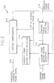
- Fig. 1 describes a preferred embodiment of an image signal encoding apparatus having a current frame prediction block of the present invention.
- a current frame signal is stored in a first frame memory 100 which is connected to a subtractor 102 through a line L11 and to a current frame prediction block 150 through a line L10.
- a current frame signal on a line L10 retrieved from the first frame memory 100 and a reconstructed previous frame signal on a line L12 from a second frame memory 124 are processed to predict the current frame on a pixel-by-pixel basis to generate a predicted current frame signal onto a line L30 and a set of motion vectors for feature points onto a line L20. Details of the current frame prediction block 150 will be described with reference to Figs. 2 and 3.
- the predicted current frame signal on the line L30 is subtracted from a current frame signal on the line L11 at the subtractor 102, and the resultant data, i.e., an error signal denoting a differential pixel value, is dispatched to an image signal encoder 105, wherein the error signal is encoded into a set of quantized transform coefficients, e.g., by using a DCT and any of the known quantization methods. Thereafter, the quantized transform coefficients are transmitted to an entropy coder 107 and an image signal decoder 113.
- the quantized transform coefficients from the image signal encoder 105 and the motion vectors transmitted through the line L20 from the current frame prediction block 150 are coded together by using, e.g., a variable length coding technique; and transmitted to a transmitter(not shown) for the transmission thereof.
- the image signal decoder 113 converts the quantized transform coefficients from the image signal decoder 105 back into a reconstructed error signal by employing an inverse quantization and an inverse discrete cosine transform.
- the reconstructed error signal from the image signal decoder 113 and the predicted current frame signal on the line L30 from the current frame prediction block 150 are combined at an adder 115 to thereby provide a reconstructed current frame signal to be stored as a previous frame in the second frame memory 124.
- FIG. 2 there are illustrated details of the current frame prediction block 150 shown in Fig. 1.
- a previous frame signal on the line L12 from the second frame memory 124 is inputted to a feature point selection block 210, a feature point motion vector detection block 212 and a motion compensation block 216.
- a number of feature points are selected among the pixels contained in the previous frame.
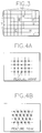
- Each of the feature points is defined as a position of a pixel which is capable of representing the motion of an object in the frame. Referring to Fig. 3, there is shown an exemplary frame of 10x7 pixels. If an moving object exists around the center of the frame and the motion of the moving object is successfully represented by a set of pixels "A" to "I", these pixels are selected as the feature points of the frame.
- the feature points are determined by a grid technique employing various types of grid, e.g., a rectangular grid or a hexagonal grid shown in Figs. 4A and 4B, respectively. As shown in Figs. 4A and 4B, the feature points are located at the nodes of the grids.
- an edge detection technique is employed together with the above described grid technique as shown in Figs. 5A and 5B.
- intersection points of the grid and the edge of the moving object are selected as feature points.
- the selected feature points from the feature point selection block 210 are inputted to a feature point motion vector detection block 212 and a current frame motion vector detection block 214. And the current frame signal on the line L10 is provided to the feature point motion vector detection block 212.
- a first set of motion vectors for each of the selected feature points is detected.
- Each of the motion vectors of the first set is a spatial displacement between a feature point in the previous frame and a most similar pixel thereto in the current frame.
- a block matching algorithm when a feature point is received from the feature point selection block 210, a feature point block having the feature point at the center thereof, e.g., 5x5 pixels of the previous frame, is retrieved via the line L12 from the second frame memory 124(shown in Fig. 1). Thereafter, a feature point motion vector for the feature point block is determined after a similarity calculation between the feature point block and each of a plurality of equal-sized candidate blocks included in a generally larger search region, e.g., 10x10 pixels of current frame retrieved from the first frame memory 100(shown in Fig. 1).
- the first set of motion vectors is provided to a current frame motion vector detection block 214 and the entropy coder 107(shown in Fig. 1) via the line L20.
- a second set of motion vectors for all of the pixels contained in the current frame is determined through the use of the first set of motion vectors and the feature point information from the feature point selection block 210.
- a set of vectors for "quasi-feature points" which represent pixel points of the current frame shifted from the feature points of the previous frame by the first set of motion vectors, are determined.
- the magnitude of a motion vector for a quasi-feature point is identical to the motion vector for its corresponding feature point but the direction of the two motion vectors is opposite.
- motion vectors for non-quasi-feature points are determined as follows.
- a motion vector for a star marked non-quasi-feature point is determined by averaging the quasi-feature points which are placed within a circle boundary having a radius of "dr+da", wherein "da” is the distance to the nearest quasi-feature point from the star marked pixel position, and "dr" is a predetermined expanded radius for including other feature points to be used in the motion vector calculation.
- the second set of motion vectors for quasi-feature points and non-quasi feature points are provided to the motion compensation block 216.
- each value of the pixels to be contained in a predicted current frame is retrieved from the second frame memory 124(shown in Fig. 1) by using each of the motion vectors contained in the second set.
- the motion prediction block is of a similar structure to that of Fig. 2 except that there is no motion estimator such as the feature point motion vector detection block 212 as shown in Fig. 2, because the feature point motion vectors transmitted from the encoder are provided thereto.
- the prediction block includes a feature point selection block, a current frame motion vector detection block and a motion compensation block whose functions are the same as those explained with respect to the encoder above.
- a previous frame signal from a frame memory of the decoder is inputted to the feature point selection block to select a number of feature points.
- the current frame motion vector detection block determines motion vectors for all of the pixels to be contained in the predicted current frame in response to the selected feature points and motion vectors transmitted from the encoder explained with reference to Fig. 2.
- the motion compensation block provides the predicted current frame which is the same as that of the encoder.
- the predicted current frame is further processed at the decoder to recover the current frame which is substantially identical to the original video signal.
Landscapes
- Engineering & Computer Science (AREA)
- Multimedia (AREA)
- Signal Processing (AREA)
- Compression Or Coding Systems Of Tv Signals (AREA)
- Compression, Expansion, Code Conversion, And Decoders (AREA)
Priority Applications (1)
| Application Number | Priority Date | Filing Date | Title |
|---|---|---|---|
| EP94120945A EP0720381A1 (fr) | 1994-12-30 | 1994-12-30 | Procédé et appareil pour le codage d'un signal vidéo par prédiction de mouvement de pixel à pixel |
Applications Claiming Priority (1)
| Application Number | Priority Date | Filing Date | Title |
|---|---|---|---|
| EP94120945A EP0720381A1 (fr) | 1994-12-30 | 1994-12-30 | Procédé et appareil pour le codage d'un signal vidéo par prédiction de mouvement de pixel à pixel |
Publications (1)
| Publication Number | Publication Date |
|---|---|
| EP0720381A1 true EP0720381A1 (fr) | 1996-07-03 |
Family
ID=8216581
Family Applications (1)
| Application Number | Title | Priority Date | Filing Date |
|---|---|---|---|
| EP94120945A Ceased EP0720381A1 (fr) | 1994-12-30 | 1994-12-30 | Procédé et appareil pour le codage d'un signal vidéo par prédiction de mouvement de pixel à pixel |
Country Status (1)
| Country | Link |
|---|---|
| EP (1) | EP0720381A1 (fr) |
Citations (2)
| Publication number | Priority date | Publication date | Assignee | Title |
|---|---|---|---|---|
| WO1992003799A1 (fr) * | 1990-08-15 | 1992-03-05 | Televerket | Procede de compensation des mouvements et de deformation elastique dans des sequences d'image |
| FI932520A (fi) * | 1993-06-02 | 1994-12-03 | Nokia Oy Ab | Menetelmä videokuvan ennustamiseksi käsittelyjärjestyksessä edellisen kuvan perusteella |
-
1994
- 1994-12-30 EP EP94120945A patent/EP0720381A1/fr not_active Ceased
Patent Citations (3)
| Publication number | Priority date | Publication date | Assignee | Title |
|---|---|---|---|---|
| WO1992003799A1 (fr) * | 1990-08-15 | 1992-03-05 | Televerket | Procede de compensation des mouvements et de deformation elastique dans des sequences d'image |
| FI932520A (fi) * | 1993-06-02 | 1994-12-03 | Nokia Oy Ab | Menetelmä videokuvan ennustamiseksi käsittelyjärjestyksessä edellisen kuvan perusteella |
| EP0632657A1 (fr) * | 1993-06-02 | 1995-01-04 | Oy Nokia Ab | Méthode pour la prédiction d'une image vidéo |
Non-Patent Citations (4)
| Title |
|---|
| C.H.HUANG ET AL.: "A new motion compensation method for image sequence coding using hierachical grid interpolation", IEEE TRANSACTIONS ON CIRCUITS AND SYSTEMS FOR VIDEO TECHNOLOGY, vol. 4, no. 1, NEW YORK US, pages 42 - 51 * |
| NAKAYA ET AL.: "An iterative motion estimation method using triangular patches for motion compensation", VISUAL COMMUNICATION AND IMAGE PROCESSING '91 - PROCEEDINGS OF THE SPIE, 1991, US, vol. 1605, no. 2, pages 546 - 557 * |
| NIEWEGLOWSKI J. ET AL.: "A novel video coding scheme based on temporal prediction using digital image warping", IEEE TRANSACTIONS ON CONSUMER ELECTRONICS, IEEE, NEW YORK, US, vol. 39, no. 3, pages 141 - 150 * |
| SULLIVAN G.J. ET AL.: "Motion compensation for video compression using control grid interpolation", ICASSP'91 - INTERNATIONAL CONFERENCE ON ACOUSTICS, SPEECH AND SIGNAL PROCESSING, TORONTO, ONTARIO, CANADA, vol. 4, 14 April 1991 (1991-04-14) - 17 April 1991 (1991-04-17), pages 2713 - 2716, XP010043566, DOI: doi:10.1109/ICASSP.1991.150962 * |
Similar Documents
| Publication | Publication Date | Title |
|---|---|---|
| US5689306A (en) | Method and apparatus for encoding a video signal using pixel-by-pixel motion prediction | |
| KR0171118B1 (ko) | 비디오신호 부호화 장치 | |
| US5612743A (en) | Method for encoding a video signal using feature point based motion estimation | |
| US5546129A (en) | Method for encoding a video signal using feature point based motion estimation | |
| KR0171146B1 (ko) | 특징점을 이용한 움직임 벡터 검출 장치 | |
| US5760846A (en) | Apparatus for estimating motion vectors for feature points of a video signal | |
| US5617144A (en) | Image processing system using pixel-by-pixel motion estimation and frame decimation | |
| US5673339A (en) | Method for encoding a video signal using feature point based motion estimation | |
| US5619281A (en) | Method and apparatus for detecting motion vectors in a frame decimating video encoder | |
| US5751362A (en) | Apparatus for encoding a video signal using feature point based motion estimation | |
| EP0771117B1 (fr) | Procédé et dispositif pour le codage et décodage d'un signal vidéo utilisant une estimation de mouvement basée sur des points caractéristiques | |
| US5638129A (en) | Image processing apparatus using a pixel-by-pixel motion estimation based on feature points | |
| EP0721284B1 (fr) | Système de traitement d'images utilisant une estimation du mouvement pixel à pixel et un décimation d'images | |
| US5627591A (en) | Image processing system using a pixel-by-pixel motion estimation based on feature points | |
| US6020925A (en) | Method and apparatus for encoding a video signal using pixel-by-pixel motion prediction | |
| US5731851A (en) | Method for determining feature points based on hierarchical block searching technique | |
| EP0731612B1 (fr) | Appareil pour le codage d'un signal vidéo employant des réseaux de recherche pour l'estimation et la compensation de mouvement | |
| US5625417A (en) | Image processing system using a feature point-based motion estimation | |
| KR0174455B1 (ko) | 화소단위 움직임예측을 이용하는 영상신호 부호화 방법 및 장치 | |
| EP0720373A1 (fr) | Méthode et appareil pour le codage d'un signal vidéo employant des vecteurs de mouvement basés sur des régions | |
| EP0720381A1 (fr) | Procédé et appareil pour le codage d'un signal vidéo par prédiction de mouvement de pixel à pixel | |
| KR0174956B1 (ko) | 픽셀단위 움직임예측을 이용하는 영상신호 부호화 방법 및 장치 | |
| JPH08205176A (ja) | 映像信号符号化装置及び映像信号符号化方法 | |
| JPH08205179A (ja) | 映像信号符号化装置及び映像信号符号化方法 | |
| CN1127970A (zh) | 利用逐象素的运动预测对视频信号进行编码的方法和装置 |
Legal Events
| Date | Code | Title | Description |
|---|---|---|---|
| PUAI | Public reference made under article 153(3) epc to a published international application that has entered the european phase |
Free format text: ORIGINAL CODE: 0009012 |
|
| AK | Designated contracting states |
Kind code of ref document: A1 Designated state(s): DE FR GB NL |
|
| 17P | Request for examination filed |
Effective date: 19961017 |
|
| 17Q | First examination report despatched |
Effective date: 19971120 |
|
| RTI1 | Title (correction) |
Free format text: METHODS AND APPARATUS FOR ENCODING OR DECODING A VIDEO SIGNAL USING PIXEL-BY-PIXEL MOTION PREDICTION |
|
| GRAG | Despatch of communication of intention to grant |
Free format text: ORIGINAL CODE: EPIDOS AGRA |
|
| STAA | Information on the status of an ep patent application or granted ep patent |
Free format text: STATUS: THE APPLICATION HAS BEEN REFUSED |
|
| 18R | Application refused |
Effective date: 20000519 |