EP0720075A2 - Off-lane alarm apparatus - Google Patents
Off-lane alarm apparatus Download PDFInfo
- Publication number
- EP0720075A2 EP0720075A2 EP95120429A EP95120429A EP0720075A2 EP 0720075 A2 EP0720075 A2 EP 0720075A2 EP 95120429 A EP95120429 A EP 95120429A EP 95120429 A EP95120429 A EP 95120429A EP 0720075 A2 EP0720075 A2 EP 0720075A2
- Authority
- EP
- European Patent Office
- Prior art keywords
- lane
- car
- pickup sensor
- processing device
- image processing
- Prior art date
- Legal status (The legal status is an assumption and is not a legal conclusion. Google has not performed a legal analysis and makes no representation as to the accuracy of the status listed.)
- Granted
Links
- 238000001514 detection method Methods 0.000 abstract description 12
- 230000003287 optical effect Effects 0.000 description 4
- 238000010586 diagram Methods 0.000 description 3
- 206010039203 Road traffic accident Diseases 0.000 description 1
- 238000000034 method Methods 0.000 description 1
- 238000012544 monitoring process Methods 0.000 description 1
- 230000002265 prevention Effects 0.000 description 1
- 230000000007 visual effect Effects 0.000 description 1
Images


Classifications
-
- G—PHYSICS
- G05—CONTROLLING; REGULATING
- G05D—SYSTEMS FOR CONTROLLING OR REGULATING NON-ELECTRIC VARIABLES
- G05D1/00—Control of position, course, altitude or attitude of land, water, air or space vehicles, e.g. using automatic pilots
- G05D1/02—Control of position or course in two dimensions
- G05D1/021—Control of position or course in two dimensions specially adapted to land vehicles
- G05D1/0231—Control of position or course in two dimensions specially adapted to land vehicles using optical position detecting means
- G05D1/0246—Control of position or course in two dimensions specially adapted to land vehicles using optical position detecting means using a video camera in combination with image processing means
-
- B—PERFORMING OPERATIONS; TRANSPORTING
- B60—VEHICLES IN GENERAL
- B60T—VEHICLE BRAKE CONTROL SYSTEMS OR PARTS THEREOF; BRAKE CONTROL SYSTEMS OR PARTS THEREOF, IN GENERAL; ARRANGEMENT OF BRAKING ELEMENTS ON VEHICLES IN GENERAL; PORTABLE DEVICES FOR PREVENTING UNWANTED MOVEMENT OF VEHICLES; VEHICLE MODIFICATIONS TO FACILITATE COOLING OF BRAKES
- B60T2201/00—Particular use of vehicle brake systems; Special systems using also the brakes; Special software modules within the brake system controller
- B60T2201/08—Lane monitoring; Lane Keeping Systems
- B60T2201/082—Lane monitoring; Lane Keeping Systems using alarm actuation
Definitions
- This invention relates to an off-lane alarm apparatus, and in particular to an off-lane alarm apparatus wherein by monitoring a road surface in front of or behind a car by means of an image pickup sensor (hereinafter referred to as pickup sensor), off-lane or deviation of the car from the traffic white or yellow lane (hereinafter abbreviated as lane) is alarmed.
- pickup sensor image pickup sensor
- an apparatus which utilizes a pickup sensor, e.g. line TV camera taking an image of the front or rear of a car in order to detect a lane for alarming the off-lane state as soon as possible.
- a pickup sensor e.g. line TV camera taking an image of the front or rear of a car in order to detect a lane for alarming the off-lane state as soon as possible.
- Fig.3 shows one arrangement of such an off-lane alarm apparatus known in the art, in which output signals from the pickup sensor 1, the winker 2, the car speed sensor 3, and the input means 4, are provided for an image processing device 5 which provides a control signal for an alarm means 6.
- the image processing device 5 receives an image signal from the pickup sensor 1, a winker signal, i.e. a turn signal from the winker 2, a car speed signal from the car speed sensor 3, and input data provided through the input means 4 by a driver or operator.
- a winker signal i.e. a turn signal from the winker 2
- a car speed signal from the car speed sensor 3
- input data provided through the input means 4 by a driver or operator.
- the image processing device 5 then converts the image signal from the image sensor 1 into binary based on which a lane on a road surface is extracted to calculate the position of the car with respect to the lane in the form of image data on the screen.
- the relative position between the lane and the car thus calculated is then checked with reference to various data provided from the input means 4. If the result reveals that the car has come off or is on the point of coming off the lane, the image processing device 5 energizes the alarm means 6 to issue an off-lane alarm in the case where the device 5 receives no turn signal from the winker 5 and the car speed sensed by the car speed sensor 3 exceeds a threshold value.
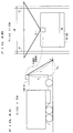
- Data provided from the input means 4 comprise a height H of the pickup sensor 1 mounted on the roof of a car cab 10 with respect to the road, a distance RL from the position right beneath the pickup sensor 1 to a predetermined point A on the road, a car width VW, a lane width LW, and a horizontal view angle ⁇ of the pickup sensor 1, as shown in the side view of Fig.4A and the plan view of Fig.4B so that an off-lane detection may be made no matter where the cab 10 is relatively positioned with respect to lanes 11, 12.
- a necessary detecting area is prepared as a range in which an image is taken over a view angle ⁇ enabling the above determinations to be made.
- Maintaining such a view angle makes it possible to give an alarm even though an off-lane driving occurs on one side where no lane exists in a road having a lane only on the other side, supposing that a lane exists at a point apart by a distance corresponding to a lane width, which is statutorily prescribed, due to a distance from the opposite lane.
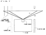
- Such a prior art off-lane alarm apparatus gives rise to a problem as shown in Fig.7 in case of the pickup sensor 1 being mounted on a roof of a cab 10a, as shown in Fig.6, which is larger in size than the cab 10 in Figs.4A, 4B.
- the pickup sensor 1 in case of the pickup sensor 1 being mounted at the lowest height H as shown in Fig.4A, it is statutorily arranged that a guardrail 13 (or a tunnel sidewall etc) existing on the left side of the blurred lane 11 does not come into view (visual field) 1, as shown in Fig. 7. If the height of the pickup sensor 1 is increased to a height H+ ⁇ H as shown in Fig. 6, the view of the pickup sensor 1 is widened to view 2 which now includes the guardrail 13 existing on the left side of the lane 11.
- the image processing device 5 will recognize the guardrail 13 as a regular lane on the basis of an image signal provided from the pickup sensor 1.
- an object of the present invention is to provide an apparatus which enables a normal off-lane alarm to be generated without changing its optical mechanism even though a mounted height of a pickup sensor on a car is increased.
- an off-lane alarm apparatus comprises an image pickup sensor mounted on a roof of a car; means for generating a turn signal for the car; means for generating an alarm; input means; and, an image processing device in which an image signal provided from the pickup sensor is converted into corresponding binary data to extract a lane on a road surface whereby an off-lane state of the car is detected on the basis of a mounted height of the pickup sensor provided from the input means, a distance between a road position right beneath the pickup sensor and a predetermined sensing position in front of the car, a predetermined lane width, and a predetermined car width, the alarm generating means being then energized by the image processing device unless the turn signal is generated: when the mounted height of the pickup sensor is increased, the image processing device being provided with the increased portion of the height from the input means and determining a necessary outside area of the predetermined lane width by using the inputs provided from the input means so that an image portion corresponding to the necessary outside area is is
- the image processing device when the mounted height of the pickup sensor is increased, receives as an input the increased portion of the height from the input means and determines a necessary outside area of the lane width as predetermined together with other inputs provided from the input means.
- the image processing device then masks pixels of the image corresponding to the necessary outside area.
- the image processing device no longer deems what is existing in the masked region, for example a guardrail, as a lane, thereby enabling an off-lane detection to be performed as if the height of the pickup sensor remains unchanged.
- the increased portion is selectable by switch means used in place of the input means.
- a car speed sensor can also used and the image processing device may detect the off-lanestate of the car when a car speed detected by the car speed sensor exceeds a predetermined value.
- Fig.1 is a processing flowchart executed by one embodiment of an image processing device used in an off-lane alarm apparatus according to the present invention. It is to be noted that the off-lane alarm apparatus according to the present invention may employ the same arrangement as that of the prior art shown in Fig.3.
- the image processing device 5 receives a lane width LW, a car width VW, a distance RL (see Fig.4A) from the position right beneath the pickup sensor 1 to a predetermined detecting position in front of the car, a mounted height H of the pickup sensor 1, and an increased portion ⁇ H (see Fig.6) of the mounted height H of the pickup sensor 1, from the input means 4 as set forth above.
- the image processing device 5 calculates an area to be masked by means of data provided from the input means 4.
- the masked area ME will be now described with reference to Fig.2.
- the image processing device 5 reads a turn signal from the winker 2 and a car speed signal from the car speed sensor 3 in the same manner as indicated above with reference to the prior art.
- Step S4 in order to mask the masked area determined at the above Step S2 from an actual screen (not shown), a pixel portion corresponding to the masked area ME is geomatically determined and is masked by means of well-known software processing.
- Step S5 a lane detection processing is performed in a relative positional relationship between the car position and the image signals read at Step S3.
- Step S6 after the detection of the lane, an off-lane decision processing is performed from a relative positional relationship between the lane and the car.
- an off-lane decision is performed on the assumption that the turn signal from the winker 2 gives no directional indication and the car speed provided from the car speed sensor 3 falls below a threshold value.
- the reason whether or not the car speed exceeds the set value is determined is to exclude such a case as the car speed is lower than the threshold value because a car normally runs on a low speed way where a lane is obscure. This determination step for the car speed is not therefore indispensable.
- Step S7 after the off-lane decision, the image processing device 5 energizes the alarm means 6 to generate an alarm output.
- the horizontal center of the pickup sensor should be directed to the predetermined position of the distance RL in front of the position right beneath the car.
- an off-lane alarm apparatus is arranged such that upon the increase of the height of a pickup sensor mounted on a car, the increased portion is provided for an image processing device which then determines a necessary outside area of a predetermined lane width with other input data to mask an image portion corresponding to the necessary outside area for the car's off-lane detection, a detected area can be fixed at the necessary detection area even though the mounted height of the pickup sensor is changed, resulting in the prevention of erroneous alarms due to unnecessary information from being induced.
Landscapes
- Engineering & Computer Science (AREA)
- Physics & Mathematics (AREA)
- Radar, Positioning & Navigation (AREA)
- Multimedia (AREA)
- Electromagnetism (AREA)
- Aviation & Aerospace Engineering (AREA)
- Computer Vision & Pattern Recognition (AREA)
- Remote Sensing (AREA)
- General Physics & Mathematics (AREA)
- Automation & Control Theory (AREA)
- Traffic Control Systems (AREA)
- Image Processing (AREA)
- Navigation (AREA)
- Closed-Circuit Television Systems (AREA)
Abstract
Description
- This invention relates to an off-lane alarm apparatus, and in particular to an off-lane alarm apparatus wherein by monitoring a road surface in front of or behind a car by means of an image pickup sensor (hereinafter referred to as pickup sensor), off-lane or deviation of the car from the traffic white or yellow lane (hereinafter abbreviated as lane) is alarmed.
- There have been known measures in which a road is intermittently embedded with protruding things on a lane for giving a driver in a car an alarm for "off-lane" state in which the car is at least partially out of it's lane with some vibrations or sounds shut within the car occurring when the car erroneously runs on the protruding things due to inattentive or doze driving and the like.
- However, such measures must be inefficiently applied to all of the roads and disadvantageously have not yet been applied to any expressway which may cause a big traffic accident. Also, when a driver becomes aware of danger from the vibrations at which tires of the car tread on the lane, a back-mirror or a fender of the car has already entered into an adjacent lane, which may enable the car collide with an car in the adjacent lane.
- Therefore, an apparatus has been recently proposed which utilizes a pickup sensor, e.g. line TV camera taking an image of the front or rear of a car in order to detect a lane for alarming the off-lane state as soon as possible.
- Fig.3 shows one arrangement of such an off-lane alarm apparatus known in the art, in which output signals from the
pickup sensor 1, thewinker 2, thecar speed sensor 3, and the input means 4, are provided for animage processing device 5 which provides a control signal for an alarm means 6. - In the operation of this off-lane alarm apparatus, after initialization, the
image processing device 5 receives an image signal from thepickup sensor 1, a winker signal, i.e. a turn signal from thewinker 2, a car speed signal from thecar speed sensor 3, and input data provided through the input means 4 by a driver or operator. - The
image processing device 5 then converts the image signal from theimage sensor 1 into binary based on which a lane on a road surface is extracted to calculate the position of the car with respect to the lane in the form of image data on the screen. - The relative position between the lane and the car thus calculated is then checked with reference to various data provided from the input means 4. If the result reveals that the car has come off or is on the point of coming off the lane, the
image processing device 5 energizes the alarm means 6 to issue an off-lane alarm in the case where thedevice 5 receives no turn signal from thewinker 5 and the car speed sensed by thecar speed sensor 3 exceeds a threshold value. - Herebelow, such a relative position between the lane and the car will be described in more detail.
- Data provided from the input means 4 comprise a height H of the
pickup sensor 1 mounted on the roof of acar cab 10 with respect to the road, a distance RL from the position right beneath thepickup sensor 1 to a predetermined point A on the road, a car width VW, a lane width LW, and a horizontal view angle θ of thepickup sensor 1, as shown in the side view of Fig.4A and the plan view of Fig.4B so that an off-lane detection may be made no matter where thecab 10 is relatively positioned with respect tolanes - For example, as shown in Fig. 5, if the car runs in the nearest possible position by the
left lane 11, an off-lane can be detected without fail due to the fact that the distance from thepickup sensor 1 to thelane 11 is shorter than a predetermined threshold value VW/2. - However, in the case where the
lane 11 is blurred or broken, since the relative position between thelane 11 and thecab 10 is made unclear, it can be determined that thecab 10 comes off theleft lane 11, provided that the distance between theopposite lane 12 and thepickup sensor 1 is larger than a threshold value LW-VW/2. - A necessary detecting area is prepared as a range in which an image is taken over a view angle θ enabling the above determinations to be made. To establish such a detecting area, it is necessary to use the
pickup sensor 1 with an optical view angle ± θ as given by the following equation:
- Such a prior art off-lane alarm apparatus gives rise to a problem as shown in Fig.7 in case of the
pickup sensor 1 being mounted on a roof of a cab 10a, as shown in Fig.6, which is larger in size than thecab 10 in Figs.4A, 4B. - Namely, in case of the
pickup sensor 1 being mounted at the lowest height H as shown in Fig.4A, it is statutorily arranged that a guardrail 13 (or a tunnel sidewall etc) existing on the left side of theblurred lane 11 does not come into view (visual field) ①, as shown in Fig. 7. If the height of thepickup sensor 1 is increased to a height H+ ΔH as shown in Fig. 6, the view of thepickup sensor 1 is widened to view ② which now includes theguardrail 13 existing on the left side of thelane 11. - In this case, if the
right lane 12 is dotted as shown in Fig.7 and theleft lane 11 is blurred, theimage processing device 5 will recognize theguardrail 13 as a regular lane on the basis of an image signal provided from thepickup sensor 1. - It is therefore disadvantageous that no alarm is generated although the
cab 10 is going to come off theleft lane 11 as shown in Fig.5 from the relative position between the recognized lane, i.e. the guardrail and thecab 10. - It is accordingly an object of the present invention is to provide an apparatus which enables a normal off-lane alarm to be generated without changing its optical mechanism even though a mounted height of a pickup sensor on a car is increased.
- For achievement of the above-noted object, an off-lane alarm apparatus according to the present invention comprises an image pickup sensor mounted on a roof of a car; means for generating a turn signal for the car; means for generating an alarm; input means; and, an image processing device in which an image signal provided from the pickup sensor is converted into corresponding binary data to extract a lane on a road surface whereby an off-lane state of the car is detected on the basis of a mounted height of the pickup sensor provided from the input means, a distance between a road position right beneath the pickup sensor and a predetermined sensing position in front of the car, a predetermined lane width, and a predetermined car width, the alarm generating means being then energized by the image processing device unless the turn signal is generated: when the mounted height of the pickup sensor is increased, the image processing device being provided with the increased portion of the height from the input means and determining a necessary outside area of the predetermined lane width by using the inputs provided from the input means so that an image portion corresponding to the necessary outside area is masked for detecting the off-lane state of the car.
- According to the present invention, when the mounted height of the pickup sensor is increased, the image processing device receives as an input the increased portion of the height from the input means and determines a necessary outside area of the lane width as predetermined together with other inputs provided from the input means.
- The image processing device then masks pixels of the image corresponding to the necessary outside area.
- Thus, the image processing device no longer deems what is existing in the masked region, for example a guardrail, as a lane, thereby enabling an off-lane detection to be performed as if the height of the pickup sensor remains unchanged.
- In another aspect of the present invention, the increased portion is selectable by switch means used in place of the input means.
- In further another aspect of the present invention, a car speed sensor can also used and the image processing device may detect the off-lanestate of the car when a car speed detected by the car speed sensor exceeds a predetermined value.
-
- Fig. 1 is a flowchart of procedures executed by an off-lane alarm apparatus according to the present invention;
- Fig.2 is a diagram for the illustration of an area to be masked in an off-lane alarm apparatus according to the present invention;
- Fig.3 is a block diagram showing one arrangement of an off-lane alarm apparatus commonly according to the present invention and prior art;
- Figs.4A and 4B are schematic side and plan views respectively of a car mounting thereon a pickup sensor used for an off-lane alarm apparatus;
- Fig.5 is a diagram for the illustration of a necessary detection area by a pickup sensor used for an off-lane alarm apparatus;
- Fig.6 is a side view showing a state where the mounted height of a pickup sensor is increased from the state shown in Fig.4A; and,
- Fig.7 is a plan view for the illustration of a detected state of unnecessary information upon the magnification of detected area by an off-lane alarm apparatus according to the prior art.
- It is to be noted that throughout the Figures, the same reference numerals indicate identical or corresponding portions.
- Fig.1 is a processing flowchart executed by one embodiment of an image processing device used in an off-lane alarm apparatus according to the present invention. It is to be noted that the off-lane alarm apparatus according to the present invention may employ the same arrangement as that of the prior art shown in Fig.3.
- Hereinafter, an embodiment of the off-lane alarm apparatus according to the present invention will be described with reference to the flowchart in Fig.1.
- At a first Step S1, the
image processing device 5 receives a lane width LW, a car width VW, a distance RL (see Fig.4A) from the position right beneath thepickup sensor 1 to a predetermined detecting position in front of the car, a mounted height H of thepickup sensor 1, and an increased portion ΔH (see Fig.6) of the mounted height H of thepickup sensor 1, from the input means 4 as set forth above. - At Step S2, the
image processing device 5 calculates an area to be masked by means of data provided from the input means 4. - The masked area ME will be now described with reference to Fig.2.
- An optical detection area SL on a road surface detected by the
pickup sensor 1 and increased in its height by ΔH is given by the following Equation.
pickup sensor 1 is increased from the above optical detection area SL, as given by the following Equation:
- Referring back to Fig.1, at Step S3, after the calculation of the area to be masked, the
image processing device 5 reads a turn signal from thewinker 2 and a car speed signal from thecar speed sensor 3 in the same manner as indicated above with reference to the prior art. - At Step S4, in order to mask the masked area determined at the above Step S2 from an actual screen (not shown), a pixel portion corresponding to the masked area ME is geomatically determined and is masked by means of well-known software processing.
- Then, at Step S5, a lane detection processing is performed in a relative positional relationship between the car position and the image signals read at Step S3.
- At Step S6, after the detection of the lane, an off-lane decision processing is performed from a relative positional relationship between the lane and the car. In this processing, an off-lane decision is performed on the assumption that the turn signal from the
winker 2 gives no directional indication and the car speed provided from thecar speed sensor 3 falls below a threshold value. - It is to be noted that the reason whether or not the car speed exceeds the set value is determined is to exclude such a case as the car speed is lower than the threshold value because a car normally runs on a low speed way where a lane is obscure. This determination step for the car speed is not therefore indispensable.
- At Step S7, after the off-lane decision, the
image processing device 5 energizes the alarm means 6 to generate an alarm output. - It is to be noted that while in the above embodiment the increased portion ΔH of the mounted height of the
pickup sensor 1 is given through the input means 4, a variably settable switch may be substituted for the input means 4 in various cars in case where the mounted height of thepickup sensor 1 as well as the increased portion thereof are preliminarily known and selectively changed over to furnish a desirable increased portion ΔH for theimage processing apparatus 5. - It is also to be noted that when a car is driven with this off-lane alarm apparatus, the horizontal center of the pickup sensor should be directed to the predetermined position of the distance RL in front of the position right beneath the car.
- As mentioned above, since an off-lane alarm apparatus according to the present invention is arranged such that upon the increase of the height of a pickup sensor mounted on a car, the increased portion is provided for an image processing device which then determines a necessary outside area of a predetermined lane width with other input data to mask an image portion corresponding to the necessary outside area for the car's off-lane detection, a detected area can be fixed at the necessary detection area even though the mounted height of the pickup sensor is changed, resulting in the prevention of erroneous alarms due to unnecessary information from being induced.
- Having described the present invention by way of the preferred embodiment, it can be seen how the objects of the invention have been attained. As this invention may be embodied in several forms without departing from the spirit of the invention, the present embodiment is therefore illustrative and not restrictive since the scope of the invention is defined by the appended claims and includes such equivalent forms as will be apparent to those skilled in the art.
Claims (3)
- An off-lane alarm apparatus comprising an image pickup sensor mounted on a roof of a car; means for generating a turn signal for said car; means for generating an alarm; input means; and, an image processing device in which an image signal provided from said pickup sensor is converted into corresponding binary data to extract a lane on a road surface whereby an off-lane state of said car is detected on the basis of a mounted height of said pickup sensor provided from said input means, a distance between a road position right beneath said pickup sensor and a predetermined sensing position in front of said car, a predetermined lane width, and a predetermined car width, said alarm generating means being then energized by said image processing device unless said turn signal is generated, said apparatus being characterized in that:
when said mounted height of said pickup sensor is increased, said image processing device being provided with the increased portion of the height from said input means and determining a necessary outside area of said predetermined lane width by using the inputs provided from said input means so that an image portion corresponding to said necessary outside area is masked for detecting the off-lane state of said car. - An off-lane alarm apparatus as claimed in claim 1, characterized in that said increased portion is selectable by a switch used in place of said input means.
- An off-lane alarm apparatus as claimed in claim 1 or 2, characterized by further comprising a car speed sensor, said image processing device detecting the off-lane of said car when a car speed detected by said car speed sensor exceeds a predetermined value.
Applications Claiming Priority (3)
| Application Number | Priority Date | Filing Date | Title |
|---|---|---|---|
| JP322876/94 | 1994-12-26 | ||
| JP32287694A JP3246243B2 (en) | 1994-12-26 | 1994-12-26 | Lane departure warning device |
| JP32287694 | 1994-12-26 |
Publications (3)
| Publication Number | Publication Date |
|---|---|
| EP0720075A2 true EP0720075A2 (en) | 1996-07-03 |
| EP0720075A3 EP0720075A3 (en) | 1996-11-20 |
| EP0720075B1 EP0720075B1 (en) | 2000-04-26 |
Family
ID=18148604
Family Applications (1)
| Application Number | Title | Priority Date | Filing Date |
|---|---|---|---|
| EP95120429A Expired - Lifetime EP0720075B1 (en) | 1994-12-26 | 1995-12-22 | Off-lane alarm apparatus |
Country Status (4)
| Country | Link |
|---|---|
| US (1) | US5689249A (en) |
| EP (1) | EP0720075B1 (en) |
| JP (1) | JP3246243B2 (en) |
| DE (1) | DE69516496T2 (en) |
Cited By (3)
| Publication number | Priority date | Publication date | Assignee | Title |
|---|---|---|---|---|
| FR2762085A1 (en) * | 1997-04-09 | 1998-10-16 | Cilas | Method for determining the position of a sensor with respect to a longitudinal guide strip, for moving vehicle guidance in public works |
| FR2770672A1 (en) * | 1997-11-04 | 1999-05-07 | Inst Nat Rech Inf Automat | METHOD AND DEVICE FOR LOCATING AND GUIDING A MOBILE PROVIDED WITH A LINEAR CAMERA |
| EP1074960A1 (en) * | 1999-07-26 | 2001-02-07 | Pioneer Corporation | Imagine processing and navigation apparatus, method, and computer program |
Families Citing this family (15)
| Publication number | Priority date | Publication date | Assignee | Title |
|---|---|---|---|---|
| JPH1069597A (en) * | 1996-08-28 | 1998-03-10 | Toyota Motor Corp | Travel lane change detection system for moving body and moving body detector to be used for the same |
| JP2000161915A (en) * | 1998-11-26 | 2000-06-16 | Matsushita Electric Ind Co Ltd | On-vehicle single-camera stereoscopic vision system |
| KR100326674B1 (en) * | 1999-03-11 | 2002-03-02 | 이계안 | Method for alarming beyond the lane in vehicle |
| US6894606B2 (en) * | 2000-11-22 | 2005-05-17 | Fred Forbes | Vehicular black box monitoring system |
| US6930593B2 (en) * | 2003-02-24 | 2005-08-16 | Iteris, Inc. | Lane tracking system employing redundant image sensing devices |
| JP4211620B2 (en) * | 2004-01-30 | 2009-01-21 | 株式会社デンソー | Car navigation system |
| JP4599894B2 (en) * | 2004-06-01 | 2010-12-15 | トヨタ自動車株式会社 | Lane departure warning device |
| JP4937030B2 (en) * | 2007-07-24 | 2012-05-23 | ルネサスエレクトロニクス株式会社 | Image processing apparatus for vehicle |
| US7843360B2 (en) * | 2008-03-21 | 2010-11-30 | Richard Louis Ponziani | Lane change turn signal appropriate use reminder system |
| US8004451B2 (en) * | 2009-05-27 | 2011-08-23 | Honeywell International Inc. | Adaptive microwave security sensor |
| KR101328363B1 (en) | 2011-06-08 | 2013-11-11 | 도요타지도샤가부시키가이샤 | Lane departure prevention support apparatus, method of displaying a lane boundary line and program |
| TWI438729B (en) | 2011-11-16 | 2014-05-21 | Ind Tech Res Inst | Method and system for lane departure warning |
| CN108638997A (en) * | 2018-03-28 | 2018-10-12 | 安徽尼古拉电子科技有限公司 | A kind of car assisted radar installations and its operation principle by arrow path |
| US11323633B2 (en) | 2019-07-01 | 2022-05-03 | Bendix Commercial Vehicle Systems, Llc | Automated creation of a freeform mask for automotive cameras |
| CN111114548B (en) * | 2019-12-04 | 2021-09-21 | 福瑞泰克智能系统有限公司 | Vehicle detection method and device, electronic equipment and storage medium |
Citations (1)
| Publication number | Priority date | Publication date | Assignee | Title |
|---|---|---|---|---|
| FR2679357A1 (en) * | 1991-07-19 | 1993-01-22 | Matra Sep Imagerie Inf | ON-BOARD DEVICE AND METHOD FOR TRACKING AND MONITORING THE POSITION OF A VEHICLE ON THE ROAD AND DRIVING AID DEVICE INCLUDING APPLICATION. |
Family Cites Families (4)
| Publication number | Priority date | Publication date | Assignee | Title |
|---|---|---|---|---|
| US4942539A (en) * | 1988-12-21 | 1990-07-17 | Gmf Robotics Corporation | Method and system for automatically determining the position and orientation of an object in 3-D space |
| US5283640A (en) * | 1992-01-31 | 1994-02-01 | Tilton Homer B | Three dimensional television camera system based on a spatial depth signal and receiver system therefor |
| JPH05265547A (en) * | 1992-03-23 | 1993-10-15 | Fuji Heavy Ind Ltd | On-vehicle outside monitoring device |
| JP3522317B2 (en) * | 1993-12-27 | 2004-04-26 | 富士重工業株式会社 | Travel guide device for vehicles |
-
1994
- 1994-12-26 JP JP32287694A patent/JP3246243B2/en not_active Expired - Fee Related
-
1995
- 1995-12-22 US US08/577,708 patent/US5689249A/en not_active Expired - Lifetime
- 1995-12-22 DE DE69516496T patent/DE69516496T2/en not_active Expired - Fee Related
- 1995-12-22 EP EP95120429A patent/EP0720075B1/en not_active Expired - Lifetime
Patent Citations (1)
| Publication number | Priority date | Publication date | Assignee | Title |
|---|---|---|---|---|
| FR2679357A1 (en) * | 1991-07-19 | 1993-01-22 | Matra Sep Imagerie Inf | ON-BOARD DEVICE AND METHOD FOR TRACKING AND MONITORING THE POSITION OF A VEHICLE ON THE ROAD AND DRIVING AID DEVICE INCLUDING APPLICATION. |
Cited By (6)
| Publication number | Priority date | Publication date | Assignee | Title |
|---|---|---|---|---|
| FR2762085A1 (en) * | 1997-04-09 | 1998-10-16 | Cilas | Method for determining the position of a sensor with respect to a longitudinal guide strip, for moving vehicle guidance in public works |
| FR2770672A1 (en) * | 1997-11-04 | 1999-05-07 | Inst Nat Rech Inf Automat | METHOD AND DEVICE FOR LOCATING AND GUIDING A MOBILE PROVIDED WITH A LINEAR CAMERA |
| WO1999023543A1 (en) * | 1997-11-04 | 1999-05-14 | Inria Institut National De Recherche En Informatique Et En Automatique | Method and device for locating and guiding a mobile unit equipped with a linear camera |
| US6654482B1 (en) | 1997-11-04 | 2003-11-25 | Michel Parent | Method and device for locating and guiding a mobile unit equipped with a linear camera |
| EP1074960A1 (en) * | 1999-07-26 | 2001-02-07 | Pioneer Corporation | Imagine processing and navigation apparatus, method, and computer program |
| US6753902B1 (en) | 1999-07-26 | 2004-06-22 | Pioneer Corporation | Image processing apparatus, image processing method, navigation apparatus, program storage device and computer data signal embodied in carrier wave |
Also Published As
| Publication number | Publication date |
|---|---|
| EP0720075A3 (en) | 1996-11-20 |
| DE69516496T2 (en) | 2000-10-26 |
| JPH08175299A (en) | 1996-07-09 |
| JP3246243B2 (en) | 2002-01-15 |
| EP0720075B1 (en) | 2000-04-26 |
| US5689249A (en) | 1997-11-18 |
| DE69516496D1 (en) | 2000-05-31 |
Similar Documents
| Publication | Publication Date | Title |
|---|---|---|
| EP0720075B1 (en) | Off-lane alarm apparatus | |
| EP0896918B1 (en) | Drive assist system for motor vehicles | |
| JP2852639B2 (en) | Apparatus for determining the distance between a vehicle and a road sign on the side | |
| US20100049405A1 (en) | Auxiliary video warning device for vehicles | |
| EP2040199B1 (en) | Stop marker recognition apparatus for a vehicle drive assist system | |
| KR20020097357A (en) | Control method for preventing a lane secession of vehicle | |
| US20070005213A1 (en) | Backward control for automobiles using telematics and method thereof | |
| KR100282903B1 (en) | Lane departure prevention device | |
| JP3271458B2 (en) | Lane departure warning device | |
| JP3141906B2 (en) | Lane departure warning device | |
| JPH03273499A (en) | Device for recognizing distance between vehicles | |
| JPH10166971A (en) | Rear and side part obstacle alarm device for vehicle | |
| JP3352157B2 (en) | Car safety equipment | |
| JPH09156437A (en) | Warning device | |
| JPH0723370A (en) | Lane deviation alarming device | |
| KR0164484B1 (en) | Over-warning suppressing method for side collision warning devcie of a car | |
| JP2005145196A (en) | Vehicle surrounding monitoring device | |
| KR20060005428A (en) | Lane departure warning system for automobiles | |
| KR100210918B1 (en) | Warning method | |
| JP3063005B2 (en) | Traffic signal ignoring vehicle detection device and warning device | |
| KR20220101812A (en) | System for preventing vehicle collision | |
| KR19980021411A (en) | Lateral Collision Warning Device | |
| KR0151672B1 (en) | Opposite side vehicle detective system on the slope road | |
| JPH03273498A (en) | Detector for running lane for vehicle | |
| KR19980051742A (en) | How to suppress the excessive alarm of the side collision warning device |
Legal Events
| Date | Code | Title | Description |
|---|---|---|---|
| PUAI | Public reference made under article 153(3) epc to a published international application that has entered the european phase |
Free format text: ORIGINAL CODE: 0009012 |
|
| AK | Designated contracting states |
Kind code of ref document: A2 Designated state(s): DE GB |
|
| PUAL | Search report despatched |
Free format text: ORIGINAL CODE: 0009013 |
|
| AK | Designated contracting states |
Kind code of ref document: A3 Designated state(s): DE GB |
|
| 17P | Request for examination filed |
Effective date: 19970403 |
|
| GRAG | Despatch of communication of intention to grant |
Free format text: ORIGINAL CODE: EPIDOS AGRA |
|
| 17Q | First examination report despatched |
Effective date: 19990408 |
|
| GRAG | Despatch of communication of intention to grant |
Free format text: ORIGINAL CODE: EPIDOS AGRA |
|
| GRAH | Despatch of communication of intention to grant a patent |
Free format text: ORIGINAL CODE: EPIDOS IGRA |
|
| GRAH | Despatch of communication of intention to grant a patent |
Free format text: ORIGINAL CODE: EPIDOS IGRA |
|
| GRAA | (expected) grant |
Free format text: ORIGINAL CODE: 0009210 |
|
| AK | Designated contracting states |
Kind code of ref document: B1 Designated state(s): DE GB |
|
| REF | Corresponds to: |
Ref document number: 69516496 Country of ref document: DE Date of ref document: 20000531 |
|
| EN | Fr: translation not filed | ||
| PGFP | Annual fee paid to national office [announced via postgrant information from national office to epo] |
Ref country code: GB Payment date: 20001120 Year of fee payment: 6 |
|
| PGFP | Annual fee paid to national office [announced via postgrant information from national office to epo] |
Ref country code: DE Payment date: 20001122 Year of fee payment: 6 |
|
| PLBE | No opposition filed within time limit |
Free format text: ORIGINAL CODE: 0009261 |
|
| STAA | Information on the status of an ep patent application or granted ep patent |
Free format text: STATUS: NO OPPOSITION FILED WITHIN TIME LIMIT |
|
| 26N | No opposition filed | ||
| PG25 | Lapsed in a contracting state [announced via postgrant information from national office to epo] |
Ref country code: GB Free format text: LAPSE BECAUSE OF NON-PAYMENT OF DUE FEES Effective date: 20011222 |
|
| REG | Reference to a national code |
Ref country code: GB Ref legal event code: IF02 |
|
| PG25 | Lapsed in a contracting state [announced via postgrant information from national office to epo] |
Ref country code: DE Free format text: LAPSE BECAUSE OF NON-PAYMENT OF DUE FEES Effective date: 20020702 |
|
| GBPC | Gb: european patent ceased through non-payment of renewal fee |
Effective date: 20011222 |