EP0718599A1 - Incremental encoder - Google Patents
Incremental encoder Download PDFInfo
- Publication number
- EP0718599A1 EP0718599A1 EP95120185A EP95120185A EP0718599A1 EP 0718599 A1 EP0718599 A1 EP 0718599A1 EP 95120185 A EP95120185 A EP 95120185A EP 95120185 A EP95120185 A EP 95120185A EP 0718599 A1 EP0718599 A1 EP 0718599A1
- Authority
- EP
- European Patent Office
- Prior art keywords
- index
- angle
- main scale
- distance
- reference point
- Prior art date
- Legal status (The legal status is an assumption and is not a legal conclusion. Google has not performed a legal analysis and makes no representation as to the accuracy of the status listed.)
- Granted
Links
- 230000003287 optical effect Effects 0.000 claims description 30
- 239000011295 pitch Substances 0.000 claims description 16
- 238000001514 detection method Methods 0.000 description 13
- 238000005259 measurement Methods 0.000 description 6
- 238000010586 diagram Methods 0.000 description 3
- 238000000034 method Methods 0.000 description 3
- 238000007493 shaping process Methods 0.000 description 3
- 238000010276 construction Methods 0.000 description 2
- 206010053615 Thermal burn Diseases 0.000 description 1
- 238000006243 chemical reaction Methods 0.000 description 1
- 238000007796 conventional method Methods 0.000 description 1
- 230000001419 dependent effect Effects 0.000 description 1
- 230000006866 deterioration Effects 0.000 description 1
- 230000005389 magnetism Effects 0.000 description 1
- 238000002360 preparation method Methods 0.000 description 1
- 230000004304 visual acuity Effects 0.000 description 1
Images


Classifications
-
- G—PHYSICS
- G01—MEASURING; TESTING
- G01D—MEASURING NOT SPECIALLY ADAPTED FOR A SPECIFIC VARIABLE; ARRANGEMENTS FOR MEASURING TWO OR MORE VARIABLES NOT COVERED IN A SINGLE OTHER SUBCLASS; TARIFF METERING APPARATUS; MEASURING OR TESTING NOT OTHERWISE PROVIDED FOR
- G01D5/00—Mechanical means for transferring the output of a sensing member; Means for converting the output of a sensing member to another variable where the form or nature of the sensing member does not constrain the means for converting; Transducers not specially adapted for a specific variable
- G01D5/26—Mechanical means for transferring the output of a sensing member; Means for converting the output of a sensing member to another variable where the form or nature of the sensing member does not constrain the means for converting; Transducers not specially adapted for a specific variable characterised by optical transfer means, i.e. using infrared, visible, or ultraviolet light
- G01D5/32—Mechanical means for transferring the output of a sensing member; Means for converting the output of a sensing member to another variable where the form or nature of the sensing member does not constrain the means for converting; Transducers not specially adapted for a specific variable characterised by optical transfer means, i.e. using infrared, visible, or ultraviolet light with attenuation or whole or partial obturation of beams of light
- G01D5/34—Mechanical means for transferring the output of a sensing member; Means for converting the output of a sensing member to another variable where the form or nature of the sensing member does not constrain the means for converting; Transducers not specially adapted for a specific variable characterised by optical transfer means, i.e. using infrared, visible, or ultraviolet light with attenuation or whole or partial obturation of beams of light the beams of light being detected by photocells
- G01D5/36—Forming the light into pulses
- G01D5/366—Particular pulse shapes
-
- G—PHYSICS
- G01—MEASURING; TESTING
- G01D—MEASURING NOT SPECIALLY ADAPTED FOR A SPECIFIC VARIABLE; ARRANGEMENTS FOR MEASURING TWO OR MORE VARIABLES NOT COVERED IN A SINGLE OTHER SUBCLASS; TARIFF METERING APPARATUS; MEASURING OR TESTING NOT OTHERWISE PROVIDED FOR
- G01D5/00—Mechanical means for transferring the output of a sensing member; Means for converting the output of a sensing member to another variable where the form or nature of the sensing member does not constrain the means for converting; Transducers not specially adapted for a specific variable
- G01D5/12—Mechanical means for transferring the output of a sensing member; Means for converting the output of a sensing member to another variable where the form or nature of the sensing member does not constrain the means for converting; Transducers not specially adapted for a specific variable using electric or magnetic means
- G01D5/244—Mechanical means for transferring the output of a sensing member; Means for converting the output of a sensing member to another variable where the form or nature of the sensing member does not constrain the means for converting; Transducers not specially adapted for a specific variable using electric or magnetic means influencing characteristics of pulses or pulse trains; generating pulses or pulse trains
- G01D5/245—Mechanical means for transferring the output of a sensing member; Means for converting the output of a sensing member to another variable where the form or nature of the sensing member does not constrain the means for converting; Transducers not specially adapted for a specific variable using electric or magnetic means influencing characteristics of pulses or pulse trains; generating pulses or pulse trains using a variable number of pulses in a train
- G01D5/2454—Encoders incorporating incremental and absolute signals
- G01D5/2455—Encoders incorporating incremental and absolute signals with incremental and absolute tracks on the same encoder
- G01D5/2457—Incremental encoders having reference marks
Definitions
- the present invention relates to an incremental encoder and, more particularly, to an incremental encoder having a rotor provided with a plurality of indices and capable of detecting a reference point or a zero point without turning the rotor one full turn.
- Encoders have been widely used for electrically measuring distances and angles. Optical encoders and magnetic encoders are quite analogous in basic configuration.
- Rotary encoders have been prevalently used for the electrical measurement of angles.
- Optical encoders in particular, incorporate advanced optical techniques, are capable of measurement in high accuracy and high resolution, have high resolving power and immune to disturbances, such as external magnetism, and have a long lifetime owing to their noncontact measuring operation.
- Optical encoders having such excellent features are applied to, for example, surveying instruments for measuring angles.
- Optical encoders employed in current surveying instruments are classified into those of the absolute system, i.e., absolute optical encoders, and those of the incremental system, i.e., incremental optical encoders.
- an absolute optical encoder In an absolute optical encoder, angle and position on a circumference are in one-to-one correspondence, and positions on a circumference are registered as absolute addresses. Therefore, position information about any position can be obtained.
- an absolute optical encoder has a complex construction and it is very difficult to construct an absolute optical encoder in a compact, lightweight construction to build the absolute optical encoder in a surveying instrument.
- an incremental optical encoder comprises a rotor 9100 provided with a main scale 9110, a stator 9200 provided with a subscale 9210, and a detecting means 9300 having components disposed with the rotor 9100 and the stator 9200 therebetween.
- the main scale 9110 formed on the rotor 9100 has graduation lines arranged at equal angular pitches, for example, angular pitches of 80 sec, in the periphery of the rotor 9100 in an occulting pattern.
- the subscale 9210 formed on the stator 9200 has graduation lines arranged at angular pitches equal to those of the main scale 9110 in an occulting pattern.
- the detecting means 9300 comprises an LED 9310, a collimator lens 9320 and a photosensor 9330.
- the LED 9310 and the photosensor 9330 are disposed with the rotor 9100 and the stator 9200 therebetween.
- the light emitted by the LED 9310 is interrupted once every time the rotor 9100 turns through an angle corresponding to one pitch of the main scale 9110, and the photosensor 9330 provides an electric signal indicating the interruption of the light.
- the electric signals provided by the photosensor 9330 are counted to detect the angle through which the rotor 9100 has turned.
- the incremental optical encoder is able to start counting the output signals of the photosensor 9330 from any position of the rotor 9100 and to measure the angle of turn of the rotor 9100 from the position where counting the output signals of the photosensor 9330 is started.
- a surveying instrument 10000 comprises a base unit 8100, a standard unit 8200 rotatably mounted on the base unit 8100 in a horizontal plane, a sighting telescope 8300 supported on the standard unit 8200 for turning in a vertical plane, a first detector 8400 for detecting the horizontal angle of the standard unit 8200, and a second detector 8500 for detecting the elevation angle of the sight line of the telescope 8300.
- the base unit 8100 is connected to a leveling plate 8150 to be fixedly mounted on a tripod or the like by leveling screws 8160.
- the level of the surveying instrument 10000 can be adjusted by turning the leveling screws 8160.
- the base unit 8100 is provided with a lower adjusting knob 8120 and a lower clamp knob 8130 to adjust and fix the base unit 8100.
- the standard unit 8200 is provided with an upper adjusting knob 8220 and an upper clamp knob 8230 to adjust and fix the standard unit 8200.
- the sighting telescope 8300 is provided with an elevation adjusting knob 8320 and an elevation clamp knob 8330 to adjust the elevation angle in the sighting direction of the sighting telescope 8300 and to fix the sighting telescope 8300 in an adjusted sighting direction.
- An optical encoder included in the second detector 8500 detects the elevation angle of the sighting direction of the sighting telescope 8300 with respect to, for example, the zenith.
- the optical encoder of the second detector 8500 is provided with an index for zero detection to determine an angle from a reference.
- the signals are counted using the index as a reference point or a zero point to measure the angle.
- An optical encoder included in the first detector 8400 for measuring the horizontal angle of the standard unit 8200 has no particular reference direction and hence does not need any reference point. Therefore, the optical encoder is an ordinary one not provided with any index.
- the incremental optical encoder provided with an index of the second detector 8500 will be described with reference to Fig. 8.
- the incremental optical encoder of the second detector 8500 comprises a rotor 8510, a stator 8520, and an optical detector 8530 comprising components disposed with the rotor 8510 and the stator 8520 therebetween.
- the rotor 8510 is provided in its periphery with a main scale 8511 having graduation lines formed at equal angular pitches, and a zero detection index 8512.
- the stator 8520 is provided with a first subscale 8521 for use in combination with the main scald 8511, and a second subscale 8522 for use in combination with the zero detecting index 8512.
- the optical detector 8530 comprises an index detecting unit and a main scale detecting unit.
- the index detecting unit comprises a first light emitting device 8531, a first collimator lens 8532 and a first photosensor 8533 and is capable of detecting the zero detecting index 8512 of the rotor 8510.
- the main scale detecting unit comprises a second light emitting device 8536, a second collimator lens 8536 and a second photosensor 8537.
- the main scale detecting unit detects light pulses produced by the occulting pattern of the main scale 8511 of the rotor 8510, the second photosensor 8537 converts the light pulses into corresponding electric signals. The electric signals are counted to determine an angle from a zero detection point.
- the leveling plate 8150 of the surveying instrument 10000 is mounted on a tripod, and the leveling plate 8150 is leveled by turning the leveling screws 8160. Then, a main switch is closed and the sighting telescope 8300 is turned one full turn to complete preparations. When the sighting telescope 8300 is turned, the rotor 8510 of the second detector 8500 is turned, the zero detecting index 8512 sets a zero point to measure an angle from the zero point.
- This conventional surveying instrument 10000 needs to turn one full turn the sighting telescope 8300 provided with the second detector 8500 including the incremental optical encoder provided with the index; that is, the zero detecting index 8512 of the rotor 8510 must be detected by the index detecting unit of the optical detector 8530 by turning the sighting telescope 8300 one full turn.
- the sighting telescope 8300 needs to be turned one full turn because the index 8512, in general, is invisible from outside. If the sighting telescope 8300 is turned quickly, the index detecting unit of the optical detector 8530 is unable to detect the zero detecting index 8512 of the rotor 8510 and hence measurement cannot be made. Accordingly, the sighting telescope 8300 must be turned at an appropriate turning speed below a certain turning speed, the appropriate turning speed is dependent unavoidably on user's intuition, which is very troublesome.
- an incremental encoder comprising: a rotor provided with a main scale; a stator provided with a first subscale; and a detecting means comprising a light source unit, an optical system and a light-receiving unit disposed with the rotor and the stator therebetween; the rotor being provided with a plurality of indices for detecting a reference point, the stator being provided with a second subscale for use in combination with the indices.
- an incremental encoder wherein the detecting means detects a specific index I1, the graduation lines of the main scale are counted until the detecting means detects the next index I2, a set reference point is determined by calculation on the basis of the counted number of graduation lines of the main scale, the angle or the distance between the reference point and the position of the index I2 is determined, the angle or the distance between the index I2 and an optional position is determined on the basis of the corresponding number graduation lines of the main scale, and the angle or the distance between the reference point and the optional position is determined by adding the angle or the distance between the reference point and the position of the index I2 to the angle or the distance between the index I2 and the optional position.
- an incremental encoder 1000 in a preferred embodiment according to the present invention comprises a rotor 100, a stator 200, and an optical detector 300 having components disposed with the rotor 100 and the stator 200 therebetween.
- the rotor 100 is provided in its periphery with a main scale 110 having graduation lines formed at equal angular pitches, and a plurality of zero detecting indices 120.
- the stator 200 is provided with a first subscale 210 for use in combination with the main scale 110, and a second subscale 220 for use in combination with the zero detecting indices 120.
- the optical detector 300 i.e., a detecting means, comprises an index detecting unit 310 and a main scale detecting unit 320.
- the index detecting unit 310 which is capable of detecting the zero detecting indices 120, comprises a first light emitting device 311, a first collimator lens 312 and a first photosensor 313.
- the main scale detecting unit 320 comprises a second light emitting device 321, a second collimator lens 322 and a second photosensor 323.
- the main scale detecting unit 320 detects light pulses produced by the occulting pattern of the main scale 110, and the second photosensor 323 converts the light pulses into corresponding electric signals.
- the electric signals provided by the second photosensor 323 are counted to detect an angle from a zero detection point.
- the first light emitting device 311 and the second light emitting device 321 may be light emitting devices of any types, such as LEDs.
- the first photosensor 313 and the second photosensor 323 may be photosensors of any types, provided that the photosensors are capable of photoelectric conversion.
- the main scale 110 and the zero detecting indices 120 of the rotor 100 will be described with reference to Fig. 2.
- the main scale 110 is an occulting pattern of graduation lines formed at equal angular pitches in the periphery of the rotor 100.
- the zero detecting indices 120 are formed in the periphery of the rotor 100 at different angular pitches so that the numbers of the graduation lines of the main scale 110 corresponding to the pitches between the adjacent indices 120 are different from each other.
- I N 3°8'0'' ⁇ N + 2'40'' ⁇ (N - 1)
- the respective positions of the indices I1 and I2 are 3°8'0'' and 6°18'40''.
- K1 is the number of the graduation lines of the main scale 110 between the position of the index I1 and an optional position
- K2 is the number of the graduation lines of the main scale 110 between the position of the index I2 and the same optional point.
- the distance L0 between a reference point (zero point) and the position of the index I2 can be determined by using the number K x ; that is, the number K x and the distance between the reference point (zero point) and the index 120 are in a one-to-one correspondence.
- the distance L1 between the position of the index I2 and the optional position can be known from the number K2.
- the distance between the reference point (zero point) and the optional position is L0 + L1, i.e., the sum of the distance L0 between the reference point (zero point) and the position of the index I2 and the distance L1 between the position of the index I2 and the optional position.
- the present invention is applicable to determining a linear distance by linearly arranging the indices and to a rotary encoder for detecting an angle by arranging the indices on a circle.
- the specific index I1 is a discretionally determined, and the next index I2 may be an index immediately behind the index I1 or an index several pitches behind the index I1. Accordingly, the present invention enables the measurement of distance or angle from any position.
- the incremental encoder 1000 has the index detecting unit 310, the main scale detecting unit 320, a controller 400, a first counter 510 and a second counter 520.
- step S4 a query is made to see whether the index detecting unit 310 has detected the first index I1.
- Step S5 is executed when the response in step S4 is affirmative, i.e., if the first index I1 has been detected, or step S4 is repeated when the response in step S4 is negative, i.e., if the first index I1 has not been detected.
- the first counter 510 starts counting pulse signals provided by the main scale detecting unit 320 and representing light pulses produced by the occulting pattern, and the second counter 520 is cleared in step S6.
- step S7 a query is made to see whether the index detecting unit 310 has detected the second index I2.
- Step S8 is executed when the response in step S7 is affirmative, i.e., if the second I2 has been detected, or step S7 is repeated when the response in step S7 is negative, i.e., if the second index I2 has not been detected.
- the second counter 520 starts counting pulse signals provided by the main scale detecting unit 320 and representing light pulses produced by the occulting pattern and the counting operation of the second counter 520 is continued to an optional position.
- step S9 the controller 400 calculates the difference between the respective counts of the first counter 510 and the second counter 520 to calculate or call an angle between the zero point and the position of the index I2 corresponding to the calculated difference between the counts.
- the controller 400 calculates the angle between the position of the index I2 and an optional position on the basis of the count indicating the position of the index I2.
- the angle between the zero point and the optional point can be determined by adding the angle between the position of the index I2 and the optional position, and the angle between the zero point and the position of the index I2.
- the first counter 510 and the second counter 520 may be cleared upon the connection of the incremental encoder 1000 to the power supply.
- the electrical configuration of an electronic circuit included in the incremental encoder 1000 will be described with reference to Fig. 5 by way of example.
- the electronic circuit comprises a main scale detection signal amplifier 601, an A/D converter 602, a rectangular pulse generator 603, a direction identifying circuit 604, a first up-down counter 605, an index detection signal amplifier 606, a waveform shaping circuit 607, a second up-down counter 608 and a CPU 609.
- the main scale detection signal amplifier 601 amplifies electric signals provided by the second photosensor 323.
- the A/D converter 602 converts the output signals of the main scale detection signal amplifier 601 into corresponding digital signals and gives the same to the CPU 609.
- the first up-down counter 605 corresponds to the first counter 510
- the second up-down counter 608 corresponds to the second counter 520.
- the direction identifying circuit 604 identifies the directions of rotation or the direction of increase or decrease.
- the index detection signal amplifier 606 amplifies electric signals provided by the first photosensor 313.
- the output signal of the main scale detection signal amplifier 601 is given to the A/D converter 602 and the rectangular pulse generator 603.
- the output signal of the main scale detection signal amplifier 601 is given to the A/D converter 602 as a signal for interpolation and to the rectangular pulse generator 603 as a count signal.
- the rectangular pulse generator 603 generates a count signal of rectangular pulses
- the direction identifying circuit 604 identifies the direction of rotation or the direction of increase or decrease
- the output signal of the direction identifying circuit 604 is given to the first up-down counter 605 and the second up-down counter 608.
- the digital output signal for interpolation provided by the A/D converter 602 is given as an interpolation data to the CPU 609.
- the waveform of the output signal of the index detection signal amplifier 606 is shaped by the waveform shaping circuit 607, and the output signal of the waveform shaping circuit 607 is given as a start signal to the first up-down counter 605 and the second up-down counter 608.
- the start signal is given to the first up-down counter 605 only when a control signal provided by the CPU 609 is ON.
- the start signal is given to the second up-down counter 608 only when the control signal provided by the CPU 609 is ON.
- the first up-down counter 605 is cleared upon the connection of the incremental encoder 1000 to the power supply, and the first up-down counter 605 starts counting operation when the first start signal is given thereto with the control signal provided by the CPU 609 ON.
- the control signal given to the first up-down counter 605 goes OFF and the control signal given to the second up-down counter 608 goes ON.
- a start signal is given to the second up-down counter 608 to make the second up-down counter 608 start counting operation.
- This electronic circuit is capable of carrying out the operation shown in Fig. 4.
- the rest of the techniques and their application to surveying instruments are the same as the conventional techniques and hence the description thereof will be omitted.
- the rotor is provided with the main scale
- the stator is provided with the first subscale
- the light source unit, the optical system and the light-receiving unit of the detecting means are disposed with the rotor and the stator therebetween
- the indices for detecting the reference position are formed on the rotor
- the second subscale for indexing is formed on the stator. Therefore, the rotor need not be turned one full turn for the detection of the zero point, and the zero point can be detected by turning the rotor through a small angle to start angle measurement.
- the indices may be formed at different pitches.
- the indices may be formed at different pitches increasing in a specific direction.
- the detecting means detects the specific index I1 and counts the graduation lines of the main scale until the next index I2 is detected, the reference point is determined by calculation on the basis of the counted number of the graduation lines of the main scale, and the angle or the distance between the reference point and the position of the index I2 can be determined.
- the detecting means detects the specific index I1 and counts the graduation lines of the main scale until the next index I2 is detected, the reference point is determined by calculation on the basis of the counted number of the graduation lines of the main scale, the angle or the distance between the reference point and the position of the index I2 is determined, the angle or the distance between the position of the index I2 and an optional position is determined on the basis of the corresponding number of graduation lines of the main scale, and the angle or the distance between the reference point and the optional position can be determined by adding the angle or the distance between the reference point and the index I2 to the angle or the distance between the position of the index I2 and the optional point.
- the present invention is applicable to magnetic encoders, rotary encoders and linear encoders.
- angle calling can be easily restarted simply by swinging the sighting telescope through a small angle in a vertical plane.
- the incremental encoder of the present invention is small in size and is capable of high performance and of preventing the deterioration of the accuracy even if the incremental encoder is operated sharply.
Abstract
Description
- The present invention relates to an incremental encoder and, more particularly, to an incremental encoder having a rotor provided with a plurality of indices and capable of detecting a reference point or a zero point without turning the rotor one full turn.
- Encoders have been widely used for electrically measuring distances and angles. Optical encoders and magnetic encoders are quite analogous in basic configuration.
- Rotary encoders have been prevalently used for the electrical measurement of angles. Optical encoders, in particular, incorporate advanced optical techniques, are capable of measurement in high accuracy and high resolution, have high resolving power and immune to disturbances, such as external magnetism, and have a long lifetime owing to their noncontact measuring operation.
- Optical encoders having such excellent features are applied to, for example, surveying instruments for measuring angles.
- Optical encoders employed in current surveying instruments are classified into those of the absolute system, i.e., absolute optical encoders, and those of the incremental system, i.e., incremental optical encoders.
- In an absolute optical encoder, angle and position on a circumference are in one-to-one correspondence, and positions on a circumference are registered as absolute addresses. Therefore, position information about any position can be obtained. However, an absolute optical encoder has a complex construction and it is very difficult to construct an absolute optical encoder in a compact, lightweight construction to build the absolute optical encoder in a surveying instrument.
- As shown in Fig. 6, an incremental optical encoder comprises a
rotor 9100 provided with amain scale 9110, astator 9200 provided with asubscale 9210, and a detecting means 9300 having components disposed with therotor 9100 and thestator 9200 therebetween. Themain scale 9110 formed on therotor 9100 has graduation lines arranged at equal angular pitches, for example, angular pitches of 80 sec, in the periphery of therotor 9100 in an occulting pattern. Thesubscale 9210 formed on thestator 9200 has graduation lines arranged at angular pitches equal to those of themain scale 9110 in an occulting pattern. The detecting means 9300 comprises anLED 9310, acollimator lens 9320 and aphotosensor 9330. TheLED 9310 and thephotosensor 9330 are disposed with therotor 9100 and thestator 9200 therebetween. When therotor 9100 rotates, the light emitted by theLED 9310 is interrupted once every time therotor 9100 turns through an angle corresponding to one pitch of themain scale 9110, and thephotosensor 9330 provides an electric signal indicating the interruption of the light. The electric signals provided by thephotosensor 9330 are counted to detect the angle through which therotor 9100 has turned. - The incremental optical encoder is able to start counting the output signals of the
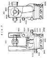
photosensor 9330 from any position of therotor 9100 and to measure the angle of turn of therotor 9100 from the position where counting the output signals of thephotosensor 9330 is started. - A surveying instrument employing an incremental optical encoder will be described with reference to Figs. 7(a) and 7(b). A
surveying instrument 10000 comprises abase unit 8100, astandard unit 8200 rotatably mounted on thebase unit 8100 in a horizontal plane, asighting telescope 8300 supported on thestandard unit 8200 for turning in a vertical plane, afirst detector 8400 for detecting the horizontal angle of thestandard unit 8200, and asecond detector 8500 for detecting the elevation angle of the sight line of thetelescope 8300. - The
base unit 8100 is connected to aleveling plate 8150 to be fixedly mounted on a tripod or the like by levelingscrews 8160. The level of thesurveying instrument 10000 can be adjusted by turning the levelingscrews 8160. Thebase unit 8100 is provided with a lower adjustingknob 8120 and alower clamp knob 8130 to adjust and fix thebase unit 8100. Thestandard unit 8200 is provided with an upper adjustingknob 8220 and anupper clamp knob 8230 to adjust and fix thestandard unit 8200. Thesighting telescope 8300 is provided with anelevation adjusting knob 8320 and anelevation clamp knob 8330 to adjust the elevation angle in the sighting direction of thesighting telescope 8300 and to fix thesighting telescope 8300 in an adjusted sighting direction. - An optical encoder included in the
second detector 8500 detects the elevation angle of the sighting direction of thesighting telescope 8300 with respect to, for example, the zenith. The optical encoder of thesecond detector 8500 is provided with an index for zero detection to determine an angle from a reference. The signals are counted using the index as a reference point or a zero point to measure the angle. An optical encoder included in thefirst detector 8400 for measuring the horizontal angle of thestandard unit 8200 has no particular reference direction and hence does not need any reference point. Therefore, the optical encoder is an ordinary one not provided with any index. - The incremental optical encoder provided with an index of the
second detector 8500 will be described with reference to Fig. 8. The incremental optical encoder of thesecond detector 8500 comprises arotor 8510, astator 8520, and an optical detector 8530 comprising components disposed with therotor 8510 and thestator 8520 therebetween. Therotor 8510 is provided in its periphery with amain scale 8511 having graduation lines formed at equal angular pitches, and a zerodetection index 8512. Thestator 8520 is provided with afirst subscale 8521 for use in combination with themain scald 8511, and asecond subscale 8522 for use in combination with the zero detectingindex 8512. The optical detector 8530 comprises an index detecting unit and a main scale detecting unit. The index detecting unit comprises a firstlight emitting device 8531, afirst collimator lens 8532 and afirst photosensor 8533 and is capable of detecting the zero detectingindex 8512 of therotor 8510. The main scale detecting unit comprises a secondlight emitting device 8536, asecond collimator lens 8536 and asecond photosensor 8537. The main scale detecting unit detects light pulses produced by the occulting pattern of themain scale 8511 of therotor 8510, thesecond photosensor 8537 converts the light pulses into corresponding electric signals. The electric signals are counted to determine an angle from a zero detection point. - A method of using the
conventional surveying instrument 10000 thus constructed will be described. Theleveling plate 8150 of thesurveying instrument 10000 is mounted on a tripod, and theleveling plate 8150 is leveled by turning the levelingscrews 8160. Then, a main switch is closed and thesighting telescope 8300 is turned one full turn to complete preparations. When thesighting telescope 8300 is turned, therotor 8510 of thesecond detector 8500 is turned, the zero detectingindex 8512 sets a zero point to measure an angle from the zero point. - This
conventional surveying instrument 10000 needs to turn one full turn thesighting telescope 8300 provided with thesecond detector 8500 including the incremental optical encoder provided with the index; that is, the zero detectingindex 8512 of therotor 8510 must be detected by the index detecting unit of the optical detector 8530 by turning thesighting telescope 8300 one full turn. Thesighting telescope 8300 needs to be turned one full turn because theindex 8512, in general, is invisible from outside. If thesighting telescope 8300 is turned quickly, the index detecting unit of the optical detector 8530 is unable to detect the zero detectingindex 8512 of therotor 8510 and hence measurement cannot be made. Accordingly, thesighting telescope 8300 must be turned at an appropriate turning speed below a certain turning speed, the appropriate turning speed is dependent unavoidably on user's intuition, which is very troublesome. - It is therefor an object of the present invention to provide an incremental encoder having a plurality of indices and capable of detecting a reference point or a zero point without turning the rotor one full turn.
- According to one aspect of the present invention, there is provided an incremental encoder comprising: a rotor provided with a main scale; a stator provided with a first subscale; and a detecting means comprising a light source unit, an optical system and a light-receiving unit disposed with the rotor and the stator therebetween;
the rotor being provided with a plurality of indices for detecting a reference point, the stator being provided with a second subscale for use in combination with the indices. - According to one aspect of the present invention, there is provided an incremental encoder wherein the detecting means detects a specific index I₁, the graduation lines of the main scale are counted until the detecting means detects the next index I₂, a set reference point is determined by calculation on the basis of the counted number of graduation lines of the main scale, the angle or the distance between the reference point and the position of the index I₂ is determined, the angle or the distance between the index I₂ and an optional position is determined on the basis of the corresponding number graduation lines of the main scale, and the angle or the distance between the reference point and the optional position is determined by adding the angle or the distance between the reference point and the position of the index I₂ to the angle or the distance between the index I₂ and the optional position.
-
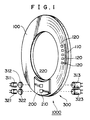
- Fig. 1 is a perspective view of an
incremental encoder 1000 in a preferred embodiment according to the present invention; - Fig. 2 is a plan view of a
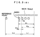
rotor 100 included in theincremental encoder 1000; - Fig. 3(a) is a diagram of assistance in explaining the principle of the present invention;
- Fig. 3(b) is a block diagram of assistance in explaining the electrical configuration of the
incremental encoder 1000 of Fig. 1; - Fig. 4 is a flow chart of assistance in explaining the operation of the
incremental encoder 1000 of Fig. 1; - Fig. 5 is a block diagram of an electronic circuit included in the
incremental encoder 1000 of Fig. 1; and - Figs. 6, 7(a), 7(b) and 8 are views of assistance in explaining a conventional surveying instrument.
- Referring to Fig. 1, an
incremental encoder 1000 in a preferred embodiment according to the present invention comprises arotor 100, astator 200, and anoptical detector 300 having components disposed with therotor 100 and thestator 200 therebetween. Therotor 100 is provided in its periphery with amain scale 110 having graduation lines formed at equal angular pitches, and a plurality of zerodetecting indices 120. Thestator 200 is provided with afirst subscale 210 for use in combination with themain scale 110, and asecond subscale 220 for use in combination with the zerodetecting indices 120. Theoptical detector 300, i.e., a detecting means, comprises anindex detecting unit 310 and a mainscale detecting unit 320. Theindex detecting unit 310, which is capable of detecting the zero detectingindices 120, comprises a firstlight emitting device 311, afirst collimator lens 312 and afirst photosensor 313. The mainscale detecting unit 320 comprises a secondlight emitting device 321, asecond collimator lens 322 and asecond photosensor 323. The mainscale detecting unit 320 detects light pulses produced by the occulting pattern of themain scale 110, and thesecond photosensor 323 converts the light pulses into corresponding electric signals. The electric signals provided by thesecond photosensor 323 are counted to detect an angle from a zero detection point. The firstlight emitting device 311 and the secondlight emitting device 321 may be light emitting devices of any types, such as LEDs. Thefirst photosensor 313 and thesecond photosensor 323 may be photosensors of any types, provided that the photosensors are capable of photoelectric conversion. - The
main scale 110 and the zero detectingindices 120 of therotor 100 will be described with reference to Fig. 2. Themain scale 110 is an occulting pattern of graduation lines formed at equal angular pitches in the periphery of therotor 100. The zero detectingindices 120 are formed in the periphery of therotor 100 at different angular pitches so that the numbers of the graduation lines of themain scale 110 corresponding to the pitches between theadjacent indices 120 are different from each other. Suppose that the indices I₁, I₂, ... and IN, are formed and the position of the index IN is expressed by:
- These different pitches between the zero detecting
indices 120 thus arranged increases in a specific direction. - Referring to Fig. 3(a), suppose that K₁ is the number of the graduation lines of the
main scale 110 between the position of the index I₁ and an optional position, and K₂ is the number of the graduation lines of themain scale 110 between the position of the index I₂ and the same optional point. Then, the number K₁ is subtracted from the number K₂;
indices 120 increases in the specific direction, the distance L₀ between a reference point (zero point) and the position of the index I₂ can be determined by using the number Kx; that is, the number Kx and the distance between the reference point (zero point) and theindex 120 are in a one-to-one correspondence. The distance L₁ between the position of the index I₂ and the optional position can be known from the number K₂. The distance between the reference point (zero point) and the optional position is L₀ + L₁, i.e., the sum of the distance L₀ between the reference point (zero point) and the position of the index I₂ and the distance L₁ between the position of the index I₂ and the optional position. - Thus, the present invention is applicable to determining a linear distance by linearly arranging the indices and to a rotary encoder for detecting an angle by arranging the indices on a circle.
- In this specification, the specific index I₁ is a discretionally determined, and the next index I₂ may be an index immediately behind the index I₁ or an index several pitches behind the index I₁. Accordingly, the present invention enables the measurement of distance or angle from any position.
- Referring to Fig. 3(b), the
incremental encoder 1000 has theindex detecting unit 310, the mainscale detecting unit 320, acontroller 400, afirst counter 510 and asecond counter 520. - The operation of the
incremental encoder 1000 will be described with reference to Fig. 4. Theincremental encoder 1000 is connected to a power supply to start angle measurement in step S1, thefirst counter 510 is cleared in step S2, and then therotor 100 is turned in step S3. In step S4, a query is made to see whether theindex detecting unit 310 has detected the first index I₁. Step S5 is executed when the response in step S4 is affirmative, i.e., if the first index I₁ has been detected, or step S4 is repeated when the response in step S4 is negative, i.e., if the first index I₁ has not been detected. In step S5, thefirst counter 510 starts counting pulse signals provided by the mainscale detecting unit 320 and representing light pulses produced by the occulting pattern, and thesecond counter 520 is cleared in step S6. - In step S7, a query is made to see whether the
index detecting unit 310 has detected the second index I₂. Step S8 is executed when the response in step S7 is affirmative, i.e., if the second I₂ has been detected, or step S7 is repeated when the response in step S7 is negative, i.e., if the second index I₂ has not been detected. In step S8, thesecond counter 520 starts counting pulse signals provided by the mainscale detecting unit 320 and representing light pulses produced by the occulting pattern and the counting operation of thesecond counter 520 is continued to an optional position. - In step S9, the
controller 400 calculates the difference between the respective counts of thefirst counter 510 and thesecond counter 520 to calculate or call an angle between the zero point and the position of the index I₂ corresponding to the calculated difference between the counts. Thecontroller 400 calculates the angle between the position of the index I₂ and an optional position on the basis of the count indicating the position of the index I₂. The angle between the zero point and the optional point can be determined by adding the angle between the position of the index I₂ and the optional position, and the angle between the zero point and the position of the index I₂. Thefirst counter 510 and thesecond counter 520 may be cleared upon the connection of theincremental encoder 1000 to the power supply. - The electrical configuration of an electronic circuit included in the
incremental encoder 1000 will be described with reference to Fig. 5 by way of example. The electronic circuit comprises a main scaledetection signal amplifier 601, an A/D converter 602, arectangular pulse generator 603, adirection identifying circuit 604, a first up-down counter 605, an indexdetection signal amplifier 606, awaveform shaping circuit 607, a second up-down counter 608 and aCPU 609. - The main scale
detection signal amplifier 601 amplifies electric signals provided by thesecond photosensor 323. The A/D converter 602 converts the output signals of the main scaledetection signal amplifier 601 into corresponding digital signals and gives the same to theCPU 609. The first up-down counter 605 corresponds to thefirst counter 510, and the second up-down counter 608 corresponds to thesecond counter 520. Thedirection identifying circuit 604 identifies the directions of rotation or the direction of increase or decrease. The indexdetection signal amplifier 606 amplifies electric signals provided by thefirst photosensor 313. - The output signal of the main scale
detection signal amplifier 601 is given to the A/D converter 602 and therectangular pulse generator 603. The output signal of the main scaledetection signal amplifier 601 is given to the A/D converter 602 as a signal for interpolation and to therectangular pulse generator 603 as a count signal. Therectangular pulse generator 603 generates a count signal of rectangular pulses, thedirection identifying circuit 604 identifies the direction of rotation or the direction of increase or decrease, and the output signal of thedirection identifying circuit 604 is given to the first up-down counter 605 and the second up-down counter 608. The digital output signal for interpolation provided by the A/D converter 602 is given as an interpolation data to theCPU 609. - The waveform of the output signal of the index
detection signal amplifier 606 is shaped by thewaveform shaping circuit 607, and the output signal of thewaveform shaping circuit 607 is given as a start signal to the first up-down counter 605 and the second up-down counter 608. The start signal is given to the first up-down counter 605 only when a control signal provided by theCPU 609 is ON. Similarly, the start signal is given to the second up-down counter 608 only when the control signal provided by theCPU 609 is ON. When the start signal is given to the first up-down counter 605 and the second up-down counter 608 with the control signal provided by turning on theCPU 609, the up-downcounters - The first up-
down counter 605 is cleared upon the connection of theincremental encoder 1000 to the power supply, and the first up-down counter 605 starts counting operation when the first start signal is given thereto with the control signal provided by theCPU 609 ON. When a count start signal is given to theCPU 609, the control signal given to the first up-down counter 605 goes OFF and the control signal given to the second up-down counter 608 goes ON. When next index is detected, a start signal is given to the second up-down counter 608 to make the second up-down counter 608 start counting operation. - This electronic circuit is capable of carrying out the operation shown in Fig. 4. The rest of the techniques and their application to surveying instruments are the same as the conventional techniques and hence the description thereof will be omitted.
- As is apparent from the foregoing description, according to the present invention, the rotor is provided with the main scale, the stator is provided with the first subscale, the light source unit, the optical system and the light-receiving unit of the detecting means are disposed with the rotor and the stator therebetween, the indices for detecting the reference position are formed on the rotor, and the second subscale for indexing is formed on the stator. Therefore, the rotor need not be turned one full turn for the detection of the zero point, and the zero point can be detected by turning the rotor through a small angle to start angle measurement.
- The indices may be formed at different pitches.The indices may be formed at different pitches increasing in a specific direction.
- The detecting means detects the specific index I₁ and counts the graduation lines of the main scale until the next index I₂ is detected, the reference point is determined by calculation on the basis of the counted number of the graduation lines of the main scale, and the angle or the distance between the reference point and the position of the index I₂ can be determined.
- The detecting means detects the specific index I₁ and counts the graduation lines of the main scale until the next index I₂ is detected, the reference point is determined by calculation on the basis of the counted number of the graduation lines of the main scale, the angle or the distance between the reference point and the position of the index I₂ is determined, the angle or the distance between the position of the index I₂ and an optional position is determined on the basis of the corresponding number of graduation lines of the main scale, and the angle or the distance between the reference point and the optional position can be determined by adding the angle or the distance between the reference point and the index I₂ to the angle or the distance between the position of the index I₂ and the optional point.
- Naturally, the present invention is applicable to magnetic encoders, rotary encoders and linear encoders.
- Even if the sighting telescope of the surveying instrument incorporating the present invention is turned quickly and errors are introduced in angle calling, angle calling can be easily restarted simply by swinging the sighting telescope through a small angle in a vertical plane.
- The incremental encoder of the present invention is small in size and is capable of high performance and of preventing the deterioration of the accuracy even if the incremental encoder is operated sharply.
Claims (5)
- An incremental encoder comprising:
a rotor provided with a main scale;
a stator provided with a first subscale; and
a detecting means comprising a light source unit, an optical system and a light-receiving unit disposed with the rotor and the stator therebetween;
said rotor being provided with a plurality of indices for detecting a reference point, said stator being provided with a second subscale for use in combination with the indices. - An incremental encoder according to claim 1, wherein the indices are arranged at different pitches.
- An incremental encoder according to claim 1, wherein the indices are arranged at different pitches increasing in a specific direction.
- An incremental encoder according to claim 1, wherein the detecting means detects a specific index I₁, the graduation lines of the main scale are counted until the detecting means detects the next index I₂, a set reference point is determined by calculation on the basis of the counted number of graduation lines of the main scale, and then the angle or the distance between the reference point and the position of the index I₂ is determined.
- An incremental encoder according to claim 1, wherein the detecting means detects a specific index I₁, the graduation lines of the main scale are counted until the detecting means detects the next index I₂, a set reference point is determined by calculation on the basis of the counted number of graduation lines of the main scale, the angle or the distance between the reference point and the position of the index I₂ is determined, the angle or the distance between the index I₂ and an optional position is determined on the basis of the corresponding number graduation lines of the main scale, and the angle or the distance between the reference point and the optional position is determined by adding the angle or the distance between the reference point and the position of the index I₂ to the angle or the distance between the index I₂ and the optional position.
Priority Applications (1)
| Application Number | Priority Date | Filing Date | Title |
|---|---|---|---|
| DE1995633468 DE69533468T3 (en) | 1994-12-22 | 1995-12-20 | Incremental encoder |
Applications Claiming Priority (3)
| Application Number | Priority Date | Filing Date | Title |
|---|---|---|---|
| JP33626894A JPH08178700A (en) | 1994-12-22 | 1994-12-22 | Incremental encoder |
| JP33626894 | 1994-12-22 | ||
| JP336268/94 | 1994-12-22 |
Publications (3)
| Publication Number | Publication Date |
|---|---|
| EP0718599A1 true EP0718599A1 (en) | 1996-06-26 |
| EP0718599B1 EP0718599B1 (en) | 2004-09-08 |
| EP0718599B2 EP0718599B2 (en) | 2011-03-16 |
Family
ID=18297361
Family Applications (1)
| Application Number | Title | Priority Date | Filing Date |
|---|---|---|---|
| EP95120185A Expired - Lifetime EP0718599B2 (en) | 1994-12-22 | 1995-12-20 | Incremental encoder |
Country Status (4)
| Country | Link |
|---|---|
| EP (1) | EP0718599B2 (en) |
| JP (1) | JPH08178700A (en) |
| CN (1) | CN1117966C (en) |
| DE (1) | DE69533468T3 (en) |
Cited By (2)
| Publication number | Priority date | Publication date | Assignee | Title |
|---|---|---|---|---|
| WO1999014590A1 (en) * | 1997-09-12 | 1999-03-25 | Shell Internationale Research Maatschappij B.V. | Device for testing of diesel fuel |
| WO2007083118A1 (en) * | 2006-01-20 | 2007-07-26 | Renishaw Plc | Rotary encoder apparatus and method |
Families Citing this family (14)
| Publication number | Priority date | Publication date | Assignee | Title |
|---|---|---|---|---|
| JP2005274261A (en) * | 2004-03-24 | 2005-10-06 | Koyo Seiko Co Ltd | Relative motion detector and bearing device comprising the same |
| JP2005337886A (en) * | 2004-05-27 | 2005-12-08 | Nok Corp | Encoder |
| JP4425078B2 (en) * | 2004-07-12 | 2010-03-03 | 浜松ホトニクス株式会社 | Encoder |
| JP5160987B2 (en) * | 2008-06-09 | 2013-03-13 | ハイデンハイン株式会社 | Encoder having rotation restricting member |
| CN101968366B (en) * | 2010-07-15 | 2013-03-20 | 南京中科天文仪器有限公司 | Automatic zeroing method and equipment for incremental sensor |
| US20120280127A1 (en) * | 2011-05-06 | 2012-11-08 | GM Global Technology Operations LLC | Two color spread spectrum optical encoder |
| CN102322878B (en) * | 2011-05-28 | 2013-07-17 | 安徽大学 | Preparation method for high-accuracy encoder and high-accuracy angle sensor |
| KR101377686B1 (en) * | 2012-05-30 | 2014-04-01 | 주식회사 져스텍 | Optical system design method based OTF for Optical encoder having different distances of image and object, and Optical encoder thereof |
| KR101308396B1 (en) * | 2012-05-30 | 2013-10-04 | 주식회사 져스텍 | Optical system design method based otf for optical encoder having same distances of image and object, and optical encoder thereof |
| US9484060B2 (en) * | 2013-08-19 | 2016-11-01 | Canon Kabushiki Kaisha | Encoder |
| JP6400345B2 (en) * | 2014-06-17 | 2018-10-03 | 株式会社ミツトヨ | Optical encoder and method of generating origin signal in optical encoder |
| JP6480564B2 (en) * | 2015-03-09 | 2019-03-13 | 株式会社Fuji | Detection device and assistance robot |
| CN109623851B (en) * | 2019-01-09 | 2021-02-09 | 北京精密机电控制设备研究所 | Zero position device and zero returning method for mechanical arm joint |
| CN112013430B (en) * | 2019-05-28 | 2023-05-26 | 佛山市顺德区美的电热电器制造有限公司 | Switch, cooking appliance, control method, control device, and computer-readable storage medium |
Citations (3)
| Publication number | Priority date | Publication date | Assignee | Title |
|---|---|---|---|---|
| EP0268558A2 (en) * | 1986-11-19 | 1988-05-25 | Leica AG | Apparatus for measuring lengths or angles |
| EP0334018A1 (en) * | 1988-03-22 | 1989-09-27 | Frankl & Kirchner GmbH. & Co. KG Fabrik für Elektromotoren und elektrische Apparate | Angular position-detecting device |
| WO1992004599A1 (en) * | 1990-09-07 | 1992-03-19 | Jenoptik Carl Zeiss Jena Gmbh | Method of measuring lengths |
Family Cites Families (2)
| Publication number | Priority date | Publication date | Assignee | Title |
|---|---|---|---|---|
| DD297701B5 (en) † | 1990-09-07 | 1993-09-23 | Carl Zeiss Jena Gmbh Zentralbe | METHOD OF MEASURING LENGTH |
| DE4037545C2 (en) † | 1990-11-26 | 1994-03-17 | Heidenhain Gmbh Dr Johannes | Measuring device |
-
1994
- 1994-12-22 JP JP33626894A patent/JPH08178700A/en active Pending
-
1995
- 1995-12-20 DE DE1995633468 patent/DE69533468T3/en not_active Expired - Lifetime
- 1995-12-20 EP EP95120185A patent/EP0718599B2/en not_active Expired - Lifetime
- 1995-12-22 CN CN95121804A patent/CN1117966C/en not_active Expired - Fee Related
Patent Citations (3)
| Publication number | Priority date | Publication date | Assignee | Title |
|---|---|---|---|---|
| EP0268558A2 (en) * | 1986-11-19 | 1988-05-25 | Leica AG | Apparatus for measuring lengths or angles |
| EP0334018A1 (en) * | 1988-03-22 | 1989-09-27 | Frankl & Kirchner GmbH. & Co. KG Fabrik für Elektromotoren und elektrische Apparate | Angular position-detecting device |
| WO1992004599A1 (en) * | 1990-09-07 | 1992-03-19 | Jenoptik Carl Zeiss Jena Gmbh | Method of measuring lengths |
Cited By (5)
| Publication number | Priority date | Publication date | Assignee | Title |
|---|---|---|---|---|
| WO1999014590A1 (en) * | 1997-09-12 | 1999-03-25 | Shell Internationale Research Maatschappij B.V. | Device for testing of diesel fuel |
| US6125690A (en) * | 1997-09-12 | 2000-10-03 | Shell Oil Company | Device for testing of diesel fuel |
| WO2007083118A1 (en) * | 2006-01-20 | 2007-07-26 | Renishaw Plc | Rotary encoder apparatus and method |
| US8017904B2 (en) | 2006-01-20 | 2011-09-13 | Renishaw Plc | Rotary encoder in which an absolute position is defined using reference mark signals produced by each of at least two readheads and method of operating the same |
| CN101371105B (en) * | 2006-01-20 | 2011-11-23 | 瑞尼斯豪公司 | Rotary encoder apparatus and method |
Also Published As
| Publication number | Publication date |
|---|---|
| DE69533468D1 (en) | 2004-10-14 |
| DE69533468T2 (en) | 2005-01-20 |
| JPH08178700A (en) | 1996-07-12 |
| EP0718599B2 (en) | 2011-03-16 |
| DE69533468T3 (en) | 2011-06-22 |
| CN1131847A (en) | 1996-09-25 |
| EP0718599B1 (en) | 2004-09-08 |
| CN1117966C (en) | 2003-08-13 |
Similar Documents
| Publication | Publication Date | Title |
|---|---|---|
| US6093928A (en) | Position measuring rotary incremental optical encoder | |
| EP0718599B1 (en) | Incremental encoder | |
| JP3168451B2 (en) | Rotary encoder | |
| US4421980A (en) | Position encoder with closed-ring diode array | |
| EP0169657A2 (en) | Non-contact shaft angle detector | |
| JP2622130B2 (en) | Length measuring device | |
| EP1010967B1 (en) | Encoder for providing incremental and absolute position data | |
| KR20130106315A (en) | Encoder | |
| US4097734A (en) | Zero index for electro-optical measuring device | |
| JP3067282B2 (en) | Movement detector | |
| JPS5822914A (en) | Zero point detecting device of photoelectric encoder | |
| US4867568A (en) | Optoelectronic measuring system | |
| US5065014A (en) | Rotation angle measuring with overlap area is between two optical grating axes | |
| WO2006107363A1 (en) | Imaging optical encoder | |
| JPH10267708A (en) | Positioning method for optical sensor | |
| CN210070775U (en) | Amesdial based on photoelectric measurement | |
| RU100311U1 (en) | PHOTOELECTRIC ANGLE CONVERTER | |
| JPH0555804B2 (en) | ||
| SU1174740A1 (en) | Device for calibrating testing of pointer-type devices with circular scale | |
| US6946648B2 (en) | Opto-electronic device for angle generation of ultrasonic probe | |
| JP2736924B2 (en) | Position detection device | |
| SU506892A1 (en) | Photoelectric converter of angular movements in a code | |
| JP3438173B2 (en) | Rotary encoder | |
| US20070138381A1 (en) | Optical encoder system | |
| Brooke | The use of encoded discs in the angle measurement systems of modern theodolites |
Legal Events
| Date | Code | Title | Description |
|---|---|---|---|
| PUAI | Public reference made under article 153(3) epc to a published international application that has entered the european phase |
Free format text: ORIGINAL CODE: 0009012 |
|
| AK | Designated contracting states |
Kind code of ref document: A1 Designated state(s): CH DE LI SE |
|
| 17P | Request for examination filed |
Effective date: 19961219 |
|
| 17Q | First examination report despatched |
Effective date: 19990311 |
|
| GRAP | Despatch of communication of intention to grant a patent |
Free format text: ORIGINAL CODE: EPIDOSNIGR1 |
|
| GRAS | Grant fee paid |
Free format text: ORIGINAL CODE: EPIDOSNIGR3 |
|
| GRAA | (expected) grant |
Free format text: ORIGINAL CODE: 0009210 |
|
| REG | Reference to a national code |
Ref country code: SE Ref legal event code: TRGR |
|
| AK | Designated contracting states |
Kind code of ref document: B1 Designated state(s): CH DE LI SE |
|
| REG | Reference to a national code |
Ref country code: CH Ref legal event code: EP |
|
| REF | Corresponds to: |
Ref document number: 69533468 Country of ref document: DE Date of ref document: 20041014 Kind code of ref document: P |
|
| REG | Reference to a national code |
Ref country code: CH Ref legal event code: NV Representative=s name: HEPP, WENGER & RYFFEL AG |
|
| PLAQ | Examination of admissibility of opposition: information related to despatch of communication + time limit deleted |
Free format text: ORIGINAL CODE: EPIDOSDOPE2 |
|
| PLBQ | Unpublished change to opponent data |
Free format text: ORIGINAL CODE: EPIDOS OPPO |
|
| PLBI | Opposition filed |
Free format text: ORIGINAL CODE: 0009260 |
|
| PLAQ | Examination of admissibility of opposition: information related to despatch of communication + time limit deleted |
Free format text: ORIGINAL CODE: EPIDOSDOPE2 |
|
| PLAR | Examination of admissibility of opposition: information related to receipt of reply deleted |
Free format text: ORIGINAL CODE: EPIDOSDOPE4 |
|
| PLBQ | Unpublished change to opponent data |
Free format text: ORIGINAL CODE: EPIDOS OPPO |
|
| PLAB | Opposition data, opponent's data or that of the opponent's representative modified |
Free format text: ORIGINAL CODE: 0009299OPPO |
|
| PLAX | Notice of opposition and request to file observation + time limit sent |
Free format text: ORIGINAL CODE: EPIDOSNOBS2 |
|
| 26 | Opposition filed |
Opponent name: DR. JOHANNES HEIDENHAIN GMBH Effective date: 20050608 |
|
| R26 | Opposition filed (corrected) |
Opponent name: DR. JOHANNES HEIDENHAIN GMBH Effective date: 20050608 |
|
| PLAF | Information modified related to communication of a notice of opposition and request to file observations + time limit |
Free format text: ORIGINAL CODE: EPIDOSCOBS2 |
|
| PLAF | Information modified related to communication of a notice of opposition and request to file observations + time limit |
Free format text: ORIGINAL CODE: EPIDOSCOBS2 |
|
| PLBB | Reply of patent proprietor to notice(s) of opposition received |
Free format text: ORIGINAL CODE: EPIDOSNOBS3 |
|
| RDAF | Communication despatched that patent is revoked |
Free format text: ORIGINAL CODE: EPIDOSNREV1 |
|
| APAH | Appeal reference modified |
Free format text: ORIGINAL CODE: EPIDOSCREFNO |
|
| APBP | Date of receipt of notice of appeal recorded |
Free format text: ORIGINAL CODE: EPIDOSNNOA2O |
|
| APBQ | Date of receipt of statement of grounds of appeal recorded |
Free format text: ORIGINAL CODE: EPIDOSNNOA3O |
|
| PGFP | Annual fee paid to national office [announced via postgrant information from national office to epo] |
Ref country code: SE Payment date: 20091207 Year of fee payment: 15 Ref country code: CH Payment date: 20091215 Year of fee payment: 15 |
|
| PGFP | Annual fee paid to national office [announced via postgrant information from national office to epo] |
Ref country code: DE Payment date: 20091217 Year of fee payment: 15 |
|
| APBU | Appeal procedure closed |
Free format text: ORIGINAL CODE: EPIDOSNNOA9O |
|
| PUAH | Patent maintained in amended form |
Free format text: ORIGINAL CODE: 0009272 |
|
| STAA | Information on the status of an ep patent application or granted ep patent |
Free format text: STATUS: PATENT MAINTAINED AS AMENDED |
|
| 27A | Patent maintained in amended form |
Effective date: 20110316 |
|
| AK | Designated contracting states |
Kind code of ref document: B2 Designated state(s): CH DE LI SE |
|
| REG | Reference to a national code |
Ref country code: CH Ref legal event code: AEN Free format text: AUFRECHTERHALTUNG DES PATENTES IN GEAENDERTER FORM |
|
| REG | Reference to a national code |
Ref country code: DE Ref legal event code: R102 Ref document number: 69533468 Country of ref document: DE Effective date: 20110316 |
|
| REG | Reference to a national code |
Ref country code: CH Ref legal event code: PL |
|
| REG | Reference to a national code |
Ref country code: SE Ref legal event code: EUG |
|
| PG25 | Lapsed in a contracting state [announced via postgrant information from national office to epo] |
Ref country code: SE Free format text: LAPSE BECAUSE OF NON-PAYMENT OF DUE FEES Effective date: 20101221 |
|
| PG25 | Lapsed in a contracting state [announced via postgrant information from national office to epo] |
Ref country code: CH Free format text: LAPSE BECAUSE OF NON-PAYMENT OF DUE FEES Effective date: 20101231 Ref country code: LI Free format text: LAPSE BECAUSE OF NON-PAYMENT OF DUE FEES Effective date: 20101231 |
|
| REG | Reference to a national code |
Ref country code: DE Ref legal event code: R119 Ref document number: 69533468 Country of ref document: DE Effective date: 20110701 |
|
| PG25 | Lapsed in a contracting state [announced via postgrant information from national office to epo] |
Ref country code: DE Free format text: LAPSE BECAUSE OF NON-PAYMENT OF DUE FEES Effective date: 20110701 |