EP0717818B1 - System zum pumpen von flüssigkeiten mit hilfe einer strahlpumpe - Google Patents
System zum pumpen von flüssigkeiten mit hilfe einer strahlpumpe Download PDFInfo
- Publication number
- EP0717818B1 EP0717818B1 EP94925562A EP94925562A EP0717818B1 EP 0717818 B1 EP0717818 B1 EP 0717818B1 EP 94925562 A EP94925562 A EP 94925562A EP 94925562 A EP94925562 A EP 94925562A EP 0717818 B1 EP0717818 B1 EP 0717818B1
- Authority
- EP
- European Patent Office
- Prior art keywords
- jet pump
- fluid
- gas
- outlet
- pressure inlet
- Prior art date
- Legal status (The legal status is an assumption and is not a legal conclusion. Google has not performed a legal analysis and makes no representation as to the accuracy of the status listed.)
- Expired - Lifetime
Links
- 239000007788 liquid Substances 0.000 title claims abstract description 17
- 238000005086 pumping Methods 0.000 title 1
- 239000012530 fluid Substances 0.000 claims abstract description 52
- 239000007789 gas Substances 0.000 description 24
- 239000012071 phase Substances 0.000 description 16
- 239000007791 liquid phase Substances 0.000 description 5
- 239000000203 mixture Substances 0.000 description 5
- 238000004519 manufacturing process Methods 0.000 description 4
- 239000000446 fuel Substances 0.000 description 3
- 238000010586 diagram Methods 0.000 description 2
- 230000000694 effects Effects 0.000 description 2
- 239000003129 oil well Substances 0.000 description 2
- 241000237858 Gastropoda Species 0.000 description 1
- 238000000605 extraction Methods 0.000 description 1
- 238000013467 fragmentation Methods 0.000 description 1
- 238000006062 fragmentation reaction Methods 0.000 description 1
- 238000011084 recovery Methods 0.000 description 1
Images
Classifications
-
- E—FIXED CONSTRUCTIONS
- E21—EARTH OR ROCK DRILLING; MINING
- E21B—EARTH OR ROCK DRILLING; OBTAINING OIL, GAS, WATER, SOLUBLE OR MELTABLE MATERIALS OR A SLURRY OF MINERALS FROM WELLS
- E21B43/00—Methods or apparatus for obtaining oil, gas, water, soluble or meltable materials or a slurry of minerals from wells
- E21B43/34—Arrangements for separating materials produced by the well
-
- B—PERFORMING OPERATIONS; TRANSPORTING
- B01—PHYSICAL OR CHEMICAL PROCESSES OR APPARATUS IN GENERAL
- B01F—MIXING, e.g. DISSOLVING, EMULSIFYING OR DISPERSING
- B01F23/00—Mixing according to the phases to be mixed, e.g. dispersing or emulsifying
- B01F23/40—Mixing liquids with liquids; Emulsifying
- B01F23/45—Mixing liquids with liquids; Emulsifying using flow mixing
- B01F23/454—Mixing liquids with liquids; Emulsifying using flow mixing by injecting a mixture of liquid and gas
-
- B—PERFORMING OPERATIONS; TRANSPORTING
- B01—PHYSICAL OR CHEMICAL PROCESSES OR APPARATUS IN GENERAL
- B01F—MIXING, e.g. DISSOLVING, EMULSIFYING OR DISPERSING
- B01F23/00—Mixing according to the phases to be mixed, e.g. dispersing or emulsifying
- B01F23/40—Mixing liquids with liquids; Emulsifying
- B01F23/49—Mixing systems, i.e. flow charts or diagrams
-
- B—PERFORMING OPERATIONS; TRANSPORTING
- B01—PHYSICAL OR CHEMICAL PROCESSES OR APPARATUS IN GENERAL
- B01F—MIXING, e.g. DISSOLVING, EMULSIFYING OR DISPERSING
- B01F25/00—Flow mixers; Mixers for falling materials, e.g. solid particles
- B01F25/30—Injector mixers
- B01F25/31—Injector mixers in conduits or tubes through which the main component flows
- B01F25/312—Injector mixers in conduits or tubes through which the main component flows with Venturi elements; Details thereof
- B01F25/3121—Injector mixers in conduits or tubes through which the main component flows with Venturi elements; Details thereof with additional mixing means other than injector mixers, e.g. screens, baffles or rotating elements
-
- B—PERFORMING OPERATIONS; TRANSPORTING
- B01—PHYSICAL OR CHEMICAL PROCESSES OR APPARATUS IN GENERAL
- B01F—MIXING, e.g. DISSOLVING, EMULSIFYING OR DISPERSING
- B01F25/00—Flow mixers; Mixers for falling materials, e.g. solid particles
- B01F25/30—Injector mixers
- B01F25/31—Injector mixers in conduits or tubes through which the main component flows
- B01F25/312—Injector mixers in conduits or tubes through which the main component flows with Venturi elements; Details thereof
- B01F25/3124—Injector mixers in conduits or tubes through which the main component flows with Venturi elements; Details thereof characterised by the place of introduction of the main flow
- B01F25/31242—Injector mixers in conduits or tubes through which the main component flows with Venturi elements; Details thereof characterised by the place of introduction of the main flow the main flow being injected in the central area of the venturi, creating an aspiration in the circumferential part of the conduit
-
- B—PERFORMING OPERATIONS; TRANSPORTING
- B01—PHYSICAL OR CHEMICAL PROCESSES OR APPARATUS IN GENERAL
- B01F—MIXING, e.g. DISSOLVING, EMULSIFYING OR DISPERSING
- B01F25/00—Flow mixers; Mixers for falling materials, e.g. solid particles
- B01F25/30—Injector mixers
- B01F25/31—Injector mixers in conduits or tubes through which the main component flows
- B01F25/313—Injector mixers in conduits or tubes through which the main component flows wherein additional components are introduced in the centre of the conduit
- B01F25/3132—Injector mixers in conduits or tubes through which the main component flows wherein additional components are introduced in the centre of the conduit by using two or more injector devices
-
- B—PERFORMING OPERATIONS; TRANSPORTING
- B01—PHYSICAL OR CHEMICAL PROCESSES OR APPARATUS IN GENERAL
- B01F—MIXING, e.g. DISSOLVING, EMULSIFYING OR DISPERSING
- B01F25/00—Flow mixers; Mixers for falling materials, e.g. solid particles
- B01F25/40—Static mixers
- B01F25/42—Static mixers in which the mixing is affected by moving the components jointly in changing directions, e.g. in tubes provided with baffles or obstructions
- B01F25/43—Mixing tubes, e.g. wherein the material is moved in a radial or partly reversed direction
- B01F25/432—Mixing tubes, e.g. wherein the material is moved in a radial or partly reversed direction with means for dividing the material flow into separate sub-flows and for repositioning and recombining these sub-flows; Cross-mixing, e.g. conducting the outer layer of the material nearer to the axis of the tube or vice-versa
-
- B—PERFORMING OPERATIONS; TRANSPORTING
- B01—PHYSICAL OR CHEMICAL PROCESSES OR APPARATUS IN GENERAL
- B01F—MIXING, e.g. DISSOLVING, EMULSIFYING OR DISPERSING
- B01F33/00—Other mixers; Mixing plants; Combinations of mixers
- B01F33/80—Mixing plants; Combinations of mixers
- B01F33/82—Combinations of dissimilar mixers
-
- E—FIXED CONSTRUCTIONS
- E21—EARTH OR ROCK DRILLING; MINING
- E21B—EARTH OR ROCK DRILLING; OBTAINING OIL, GAS, WATER, SOLUBLE OR MELTABLE MATERIALS OR A SLURRY OF MINERALS FROM WELLS
- E21B43/00—Methods or apparatus for obtaining oil, gas, water, soluble or meltable materials or a slurry of minerals from wells
- E21B43/12—Methods or apparatus for controlling the flow of the obtained fluid to or in wells
-
- F—MECHANICAL ENGINEERING; LIGHTING; HEATING; WEAPONS; BLASTING
- F04—POSITIVE - DISPLACEMENT MACHINES FOR LIQUIDS; PUMPS FOR LIQUIDS OR ELASTIC FLUIDS
- F04F—PUMPING OF FLUID BY DIRECT CONTACT OF ANOTHER FLUID OR BY USING INERTIA OF FLUID TO BE PUMPED; SIPHONS
- F04F5/00—Jet pumps, i.e. devices in which flow is induced by pressure drop caused by velocity of another fluid flow
- F04F5/02—Jet pumps, i.e. devices in which flow is induced by pressure drop caused by velocity of another fluid flow the inducing fluid being liquid
- F04F5/10—Jet pumps, i.e. devices in which flow is induced by pressure drop caused by velocity of another fluid flow the inducing fluid being liquid displacing liquids, e.g. containing solids, or liquids and elastic fluids
-
- B—PERFORMING OPERATIONS; TRANSPORTING
- B01—PHYSICAL OR CHEMICAL PROCESSES OR APPARATUS IN GENERAL
- B01F—MIXING, e.g. DISSOLVING, EMULSIFYING OR DISPERSING
- B01F23/00—Mixing according to the phases to be mixed, e.g. dispersing or emulsifying
- B01F23/20—Mixing gases with liquids
- B01F23/23—Mixing gases with liquids by introducing gases into liquid media, e.g. for producing aerated liquids
-
- B—PERFORMING OPERATIONS; TRANSPORTING
- B01—PHYSICAL OR CHEMICAL PROCESSES OR APPARATUS IN GENERAL
- B01F—MIXING, e.g. DISSOLVING, EMULSIFYING OR DISPERSING
- B01F23/00—Mixing according to the phases to be mixed, e.g. dispersing or emulsifying
- B01F23/40—Mixing liquids with liquids; Emulsifying
Definitions
- Jet pumps operate by introducing a high pressure or primary fluid through a nozzle and allowing the low pressure or secondary fluid to be entrained into the flow stream. Due to the momentum exchange between the two fluids the resulting pressure of the combined stream will be increased to well above the pressure of the secondary fluid.
- An application of mingling liquids is in fuel extraction. Gas or liquid or a mixture of the two phases is extracted from a fuel field. Many fields have a significant variation in production characteristics because of reservoir fragmentation and presence of different production zones. This often results in wells having different flowing wellhead pressures.
- Jet pumps can be used for such mingling and work satisfactorily when the primary and secondary fluids are both liquids, or both gases.
- jet pumps can also be designed to operate satisfactorily when the primary fluid is pure liquid and the secondary fluid consists of a liquid/gas mixture.
- jet pump operation cannot be achieved when there is a wide variation in the phase proportions in the primary fluid.
- the present invention is aimed at overcoming this problem by providing a co-mingling device according to claim 1 in which the jet pump is provided with a phase separator in the primary line, and utilising the liquid phase obtained from the separator as the primary fluid of the jet pump.
- a bypass arrangement is provided for the separated gas phase to be mixed back into the fluids from the outlet of the jet pump.
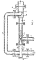
- Sources of high and low pressure fluids for the jet pump are obtained in this example from underground oil wells, a first source of fluid 11 under low pressure and a second source of fluid 12 under high pressure. Both fluids are mixtures of gas and liquid. The fluid from the high pressure oil well is used to pump fluid from the low pressure well.
- the fluid mixture under low pressure is supplied to the low pressure inlet 14G of a conventional jet pump 14.
- the high pressure fluid passes first to an in-line separator 15, in which the lighter phase tends to return to the line of entry and the heavier fluids are deflected from that line. This is usually achieved by imparting a swirl to the incoming fluid, the centrifugal force acting to separate the different phases.
- the gas rich fluid tends to collect along the axis of the swirl, in line with the incoming fluid and the heavier phase is collected from an off-axis outlet.
- the liquid phase (or liquid rich fluid) 15L separated from the high pressure fluid is supplied as primary fluid to the high pressure inlet 14L of the jet pump 14.
- the gas-rich phase 15G separated from the high pressure fluid passes through a bypass conduit 24, and the conduit may be provided with a device for controlling the flow of the gas in the bypass conduit; the device may be an orifice plate, a nozzle (as illustrated at 26) at the end of the bypass conduit 24 or a controllable valve, which is useful when inlet pressures may vary during operation.
- the jet pump 14 Since the primary fluid reaching the high pressure inlet 14L of the jet pump is substantially all liquid phase, the jet pump 14 operates satisfactorily to draw low pressure fluid from the first source through the pump and the mixture of liquids passes from the jet pump outlet 27, into a mixing device 28 where it is mixed with the gas stream from the separator 15.
- the mixing device 28 is housed in an extension of the outlet pipe 27 of the jet pump; the diameter of the extension increases in the region of the entry of the gas bypass conduit outlet.
- the role of the mixing device is to allow efficient entry of the bypass gas into the fluid leaving the jet pump. Since the pressure of the two fluids may be comparable at this point the mixing device must reduce the effect which the high pressure bypass gas may have in restricting the flow out of the jet pump.
- bypass gas is problably at a higher pressure than the fluids in the outlet of the jet pump and so it is preferable for the outlet of the bypass conduit to form what can be seen as another jet pump in the outlet conduit from the main jet pump, thus assisting the flow of fluids from the main jet pump, recovering momentum lost from the high pressure oil stream at the phase separator.
- bypass gases should be introduced in a streamline manner, such as by directing the gases axially along the outlet conduit, to prevent any disruption of the flow from the outlet of the main jet pump.
- the effect of the outlet fluids from the main jet pump on the flow of gas in the bypass conduit controls the operation of the phase separator; its back pressure discourages any carry-over of liquid slugs through the bypass conduit; it is thus a passive controller.
- the gas from the separator 15 need not be mixed back with the output fluids from the jet pump.
- the gas may for example be fed to a flare or a fuel system.
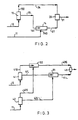
- FIG 3 there are two jet pumps 31, 32 in parallel and two phase separators 41, 42, one in the supply from each well.
- the first jet pump 31 receives liquid at each of its inputs, the liquid phase output 41L from the high pressure well separator 41 as its primary fluid and the liquid phase output 42L from the low pressure well separator 42 as its secondary input, co-mingling them to produce a liquid supply 43L to the single mixing device 43.
- the second pump 32 receives gas-rich fluid at each of its inputs, the gas phase output 41G from the high pressure well separator 41 as its primary fluid and the gas phase output 42G from the low pressure well separator 42 as its secondary fluid, comingling the gases to produce a gas supply 43G to a single mixing device 43. Jet pumps receiving the same phase for primary and secondary fluids have improved performance, as was pointed out in the introduction to the specification.
- the jet pump 14 in Figures 1 and 2 has a liquid enriched supply of driving fluid, but the supply from the low pressure well is unseparated and so may contain unsatisfactory amount of gas.
- both jet pumps 31, 32 have phase separated supplies and so do not have to deal with such a wide range of phase proportions; they can therefore be much more closely designed and so should work more efficiently.
Landscapes
- Engineering & Computer Science (AREA)
- Chemical & Material Sciences (AREA)
- Chemical Kinetics & Catalysis (AREA)
- Life Sciences & Earth Sciences (AREA)
- Geology (AREA)
- Mining & Mineral Resources (AREA)
- Physics & Mathematics (AREA)
- Fluid Mechanics (AREA)
- Geochemistry & Mineralogy (AREA)
- General Life Sciences & Earth Sciences (AREA)
- Environmental & Geological Engineering (AREA)
- Dispersion Chemistry (AREA)
- Mechanical Engineering (AREA)
- General Engineering & Computer Science (AREA)
- Jet Pumps And Other Pumps (AREA)
- Cyclones (AREA)
Claims (5)
- Vorrichtung für das Zusammenmischen, die aufweist: eine Strahlpumpe (14, 31) mit einem Hochdruckeintritt (14L, 41L), einem Niederdruckeintritt (14G, 42L) und einem Hauptaustritt (27, 43L), eine Phasentrenneinrichtung (15, 41) mit einem Austritt für das flüssigkeitsreiche fließende Medium (15L, 41L), der mit dem Hochdruckeintritt verbunden ist, und einem Austritt für das gasreiche fließende Medium (15G, 41G), der mit dem Hauptaustritt verbunden ist, wobei die fließenden Medien aus dem Austritt für das gasreiche fließende Medium (15G, 41G) mit den fließenden Medien von der Strahlpumpe (14, 31) erst gemischt werden, nachdem sie zum Hauptaustritt (27, 43L) gelangt sind.
- Vorrichtung nach Anspruch 1, bei der der Austritt für das gasreiche fließende Medium (15G) mit dem Hauptaustritt mittels einer Düse (26) verbunden ist, die längs der Achse des Hauptaustrittes ausgerichtet ist.
- Vorrichtung nach Anspruch 1 oder Anspruch 2, wobei die Strahlpumpe eine erste Strahlpumpe (31) mit einem Hochdruckeintritt, einem Niederdruckeintritt und einem Hauptaustritt ist, und wobei die Phasentrenneinrichtung eine erste Phasentrenneinrichtung (41) mit einem Austritt für das flüssigkeitsreiche fließende Medium ist, der mit dem Hochdruckeintritt der erste Strahlpumpe verbunden ist, und wobei die Vorrichtung aufweist: eine zweite Strahlpumpe (32) mit einem Hochdruckeintritt, einem Niederdruckeintritt und einem Hauptaustritt, und eine zweite Phasentrenneinrichtung (42) mit einem Austritt für das flüssigkeitsreiche fließende Medium, der mit dem Niederdruckeintritt der ersten Strahlpumpe verbunden ist, wobei die erste Phasentrenneinrichtung einen Austritt für das gasreiche fließende Medium aufweist, der mit dem Hochdruckeintritt der zweiten Strahlpumpe verbunden ist, und wobei die zweite Phasentrenneinrichtung einen Austritt für das gasreiche fließende Medium aufweist, der mit dem Niederdruckeintritt der zweiten Strahlpumpe verbunden ist.
- Vorrichtung nach Anspruch 3, die eine Einrichtung (43) aufweist, um die Austritte der zwei Strahlpumpen (31, 32) zu mischen.
- Vorrichtung nach einem der Ansprüche 1 bis 4, worin die oder jede Phasentrenneinrichtung eine mitlaufende Trenneinrichtung ist, wobei der Austritt für das gasreiche fließende Medium (15G, 41G) mit dem Eintritt der Phasentrenneinrichtung ausgerichtet ist.
Applications Claiming Priority (3)
| Application Number | Priority Date | Filing Date | Title |
|---|---|---|---|
| GB939318419A GB9318419D0 (en) | 1993-09-06 | 1993-09-06 | Pumping liquids using a jet pump |
| GB9318419 | 1993-09-06 | ||
| PCT/GB1994/001937 WO1995007414A1 (en) | 1993-09-06 | 1994-09-06 | System for pumping liquids using a jet pump |
Publications (2)
| Publication Number | Publication Date |
|---|---|
| EP0717818A1 EP0717818A1 (de) | 1996-06-26 |
| EP0717818B1 true EP0717818B1 (de) | 1998-05-27 |
Family
ID=10741559
Family Applications (1)
| Application Number | Title | Priority Date | Filing Date |
|---|---|---|---|
| EP94925562A Expired - Lifetime EP0717818B1 (de) | 1993-09-06 | 1994-09-06 | System zum pumpen von flüssigkeiten mit hilfe einer strahlpumpe |
Country Status (11)
| Country | Link |
|---|---|
| EP (1) | EP0717818B1 (de) |
| JP (1) | JPH09502779A (de) |
| AT (1) | ATE166703T1 (de) |
| AU (1) | AU687862B2 (de) |
| BR (1) | BR9407387A (de) |
| DE (1) | DE69410619T2 (de) |
| DK (1) | DK0717818T3 (de) |
| ES (1) | ES2117291T3 (de) |
| GB (2) | GB9318419D0 (de) |
| NO (1) | NO307758B1 (de) |
| WO (1) | WO1995007414A1 (de) |
Cited By (4)
| Publication number | Priority date | Publication date | Assignee | Title |
|---|---|---|---|---|
| US6026904A (en) * | 1998-07-06 | 2000-02-22 | Atlantic Richfield Company | Method and apparatus for commingling and producing fluids from multiple production reservoirs |
| GB2499473A (en) * | 2012-02-20 | 2013-08-21 | Caltec Ltd | Gas lift system with surface jet pump |
| US8747679B2 (en) | 2008-01-22 | 2014-06-10 | Caltec Limited | Separation system and method for separating a fluid mixture with this separating system |
| US10167706B2 (en) | 2015-03-13 | 2019-01-01 | Caltec Production Solutions Limited | Oil/gas production apparatus |
Families Citing this family (14)
| Publication number | Priority date | Publication date | Assignee | Title |
|---|---|---|---|---|
| FR2759113B1 (fr) * | 1997-01-31 | 1999-03-19 | Elf Aquitaine | Installation de pompage d'un effluent biphasique liquide/gaz |
| US6336503B1 (en) | 2000-03-03 | 2002-01-08 | Pancanadian Petroleum Limited | Downhole separation of produced water in hydrocarbon wells, and simultaneous downhole injection of separated water and surface water |
| US6336504B1 (en) | 2000-03-03 | 2002-01-08 | Pancanadian Petroleum Limited | Downhole separation and injection of produced water in naturally flowing or gas-lifted hydrocarbon wells |
| US6539878B1 (en) | 2000-08-29 | 2003-04-01 | National Steel Car Limited | Vehicle carrying rail road car with bridge plate assembly |
| US7255047B1 (en) | 2000-08-29 | 2007-08-14 | National Steel Car Limited | Vehicle carrying rail road car and bridge plate therefor |
| US6968788B1 (en) | 2000-08-29 | 2005-11-29 | National Steel Car Limited | Vehicle carrying rail road car with deck access fittings |
| US6537349B2 (en) * | 2001-03-27 | 2003-03-25 | Conoco, Inc. | Passive low pressure flash gas compression system |
| GB2399864A (en) * | 2003-03-22 | 2004-09-29 | Ellastar Ltd | A system and process for pumping multiphase fluids |
| GB2418213B (en) * | 2004-09-21 | 2009-09-09 | Caltec Ltd | Well start-up system and process |
| BRPI0703726B1 (pt) * | 2007-10-10 | 2018-06-12 | Petróleo Brasileiro S.A. - Petrobras | Módulo de bombeio e sistema para bombeio submarino de produção de hidrocarbonetos com alta fração de gás associado |
| GB2461874B (en) | 2008-07-14 | 2012-11-21 | Caltec Ltd | Separation system and method |
| KR101459888B1 (ko) * | 2013-03-28 | 2014-11-07 | 현대중공업 주식회사 | 해양플랜트용 해양자원 이송장치 |
| GB2526820B (en) * | 2014-06-03 | 2020-07-29 | Caltec Production Solutions Ltd | System and process for pumping fluids |
| CN110173471A (zh) * | 2019-07-02 | 2019-08-27 | 北京合利能科技有限公司 | 一种供热用平衡泵 |
Family Cites Families (3)
| Publication number | Priority date | Publication date | Assignee | Title |
|---|---|---|---|---|
| GB2101216B (en) * | 1981-06-26 | 1984-10-24 | Plessey Co Plc | A jet pump |
| GB8925402D0 (en) * | 1989-11-10 | 1989-12-28 | British Hydromechanics | Pumping liquid/gas mixture |
| GB2264147A (en) * | 1992-02-12 | 1993-08-18 | Peco Machine Shop & Inspection | Multi-phase pumping arrangement |
-
1993
- 1993-09-06 GB GB939318419A patent/GB9318419D0/en active Pending
-
1994
- 1994-09-06 DE DE69410619T patent/DE69410619T2/de not_active Expired - Lifetime
- 1994-09-06 EP EP94925562A patent/EP0717818B1/de not_active Expired - Lifetime
- 1994-09-06 AT AT94925562T patent/ATE166703T1/de not_active IP Right Cessation
- 1994-09-06 DK DK94925562T patent/DK0717818T3/da active
- 1994-09-06 BR BR9407387A patent/BR9407387A/pt not_active IP Right Cessation
- 1994-09-06 GB GB9604504A patent/GB2296045B/en not_active Expired - Fee Related
- 1994-09-06 AU AU75427/94A patent/AU687862B2/en not_active Expired
- 1994-09-06 WO PCT/GB1994/001937 patent/WO1995007414A1/en not_active Ceased
- 1994-09-06 ES ES94925562T patent/ES2117291T3/es not_active Expired - Lifetime
- 1994-09-06 JP JP7508529A patent/JPH09502779A/ja active Pending
-
1996
- 1996-03-05 NO NO19960886A patent/NO307758B1/no not_active IP Right Cessation
Non-Patent Citations (1)
| Title |
|---|
| Offshore, Vol.54, No8, Aug.1994, pages 52,54: M.M.Sarshar : High pressure wells drive low pressure producers * |
Cited By (5)
| Publication number | Priority date | Publication date | Assignee | Title |
|---|---|---|---|---|
| US6026904A (en) * | 1998-07-06 | 2000-02-22 | Atlantic Richfield Company | Method and apparatus for commingling and producing fluids from multiple production reservoirs |
| US8747679B2 (en) | 2008-01-22 | 2014-06-10 | Caltec Limited | Separation system and method for separating a fluid mixture with this separating system |
| GB2499473A (en) * | 2012-02-20 | 2013-08-21 | Caltec Ltd | Gas lift system with surface jet pump |
| GB2499473B (en) * | 2012-02-20 | 2016-03-23 | Caltec Ltd | Improved gas lift system for oil production |
| US10167706B2 (en) | 2015-03-13 | 2019-01-01 | Caltec Production Solutions Limited | Oil/gas production apparatus |
Also Published As
| Publication number | Publication date |
|---|---|
| GB2296045A (en) | 1996-06-19 |
| WO1995007414A1 (en) | 1995-03-16 |
| JPH09502779A (ja) | 1997-03-18 |
| AU7542794A (en) | 1995-03-27 |
| BR9407387A (pt) | 1996-10-29 |
| ATE166703T1 (de) | 1998-06-15 |
| EP0717818A1 (de) | 1996-06-26 |
| NO307758B1 (no) | 2000-05-22 |
| NO960886L (no) | 1996-03-05 |
| DE69410619D1 (de) | 1998-07-02 |
| DK0717818T3 (da) | 1999-02-15 |
| NO960886D0 (no) | 1996-03-05 |
| GB2296045B (en) | 1996-11-20 |
| DE69410619T2 (de) | 1998-12-03 |
| ES2117291T3 (es) | 1998-08-01 |
| GB9318419D0 (en) | 1993-10-20 |
| AU687862B2 (en) | 1998-03-05 |
| GB9604504D0 (en) | 1996-05-01 |
Similar Documents
| Publication | Publication Date | Title |
|---|---|---|
| US6162021A (en) | System for pumping liquids using a jet pump and a phase separator | |
| EP0717818B1 (de) | System zum pumpen von flüssigkeiten mit hilfe einer strahlpumpe | |
| US6007306A (en) | Multiphase pumping system with feedback loop | |
| US6383262B1 (en) | Energy recovery in a wellbore | |
| US6336504B1 (en) | Downhole separation and injection of produced water in naturally flowing or gas-lifted hydrocarbon wells | |
| AU592968B2 (en) | Hydrocyclone with inlet mixer | |
| DE602004008046T2 (de) | System und verfahren zum pumpen von mehrphasenfluiden | |
| US20050001062A1 (en) | Mixing arrangement for atomizing nozzle in multi-phase flow | |
| US4859347A (en) | Centrifugal separator | |
| EP0477845A1 (de) | In-Linie-Dispersion eines Gases in einer Flüssigkeit | |
| US3486297A (en) | Liquid and gas pumping unit | |
| WO1995007414B1 (en) | System for pumping liquids using a jet pump | |
| US8353411B2 (en) | Hydrocyclone | |
| GB2239676A (en) | Pumping gas/liquid mixtures | |
| JP2636336B2 (ja) | 入口リザーバを具える遠心ポンプ装置 | |
| US6120254A (en) | Jet pump for creating the vacuum conditions required for liquid product distillation | |
| US6348134B1 (en) | Plant for the distillation of a liquid product | |
| JPS62191671A (ja) | 流体の汲み上げ方法及び装置 | |
| US2665975A (en) | Apparatus for countercurrent contact of fluid materials | |
| US4310335A (en) | Method and apparatus for conveying through a pipe a diphasic fluid of high free gas content | |
| US9073064B2 (en) | Cyclonic separation system comprising gas injection means and method for separating a fluid mixture | |
| US5218985A (en) | Method and apparatus for eliminating unequal phase splitting at piping junctions | |
| RU2115029C1 (ru) | Способ создания вакуума и насосно-эжекторная установка для осуществления способа | |
| US5899273A (en) | Eductor/ejector apparatus and the process for increasing fluid recovery from geothermal wells | |
| US6364624B1 (en) | Operation method for a pumping-ejection apparatus and pumping-ejection apparatus for realizing this method |
Legal Events
| Date | Code | Title | Description |
|---|---|---|---|
| PUAI | Public reference made under article 153(3) epc to a published international application that has entered the european phase |
Free format text: ORIGINAL CODE: 0009012 |
|
| 17P | Request for examination filed |
Effective date: 19960307 |
|
| AK | Designated contracting states |
Kind code of ref document: A1 Designated state(s): AT BE CH DE DK ES FR GB IT LI NL SE |
|
| RIN1 | Information on inventor provided before grant (corrected) |
Inventor name: BUTCHER, MICHAEL THOMAS RALPH Inventor name: ARATO, EMIL GYORGY DR. Inventor name: SARSHAR, MIR, MAHMOOD |
|
| 17Q | First examination report despatched |
Effective date: 19961129 |
|
| GRAG | Despatch of communication of intention to grant |
Free format text: ORIGINAL CODE: EPIDOS AGRA |
|
| GRAG | Despatch of communication of intention to grant |
Free format text: ORIGINAL CODE: EPIDOS AGRA |
|
| GRAG | Despatch of communication of intention to grant |
Free format text: ORIGINAL CODE: EPIDOS AGRA |
|
| GRAH | Despatch of communication of intention to grant a patent |
Free format text: ORIGINAL CODE: EPIDOS IGRA |
|
| GRAH | Despatch of communication of intention to grant a patent |
Free format text: ORIGINAL CODE: EPIDOS IGRA |
|
| GRAA | (expected) grant |
Free format text: ORIGINAL CODE: 0009210 |
|
| AK | Designated contracting states |
Kind code of ref document: B1 Designated state(s): AT BE CH DE DK ES FR GB IT LI NL SE |
|
| REF | Corresponds to: |
Ref document number: 166703 Country of ref document: AT Date of ref document: 19980615 Kind code of ref document: T |
|
| REG | Reference to a national code |
Ref country code: CH Ref legal event code: EP |
|
| REF | Corresponds to: |
Ref document number: 69410619 Country of ref document: DE Date of ref document: 19980702 |
|
| ITF | It: translation for a ep patent filed | ||
| REG | Reference to a national code |
Ref country code: CH Ref legal event code: NV Representative=s name: RITSCHER & SEIFERT PATENTANWAELTE VSP |
|
| REG | Reference to a national code |
Ref country code: ES Ref legal event code: FG2A Ref document number: 2117291 Country of ref document: ES Kind code of ref document: T3 |
|
| ET | Fr: translation filed | ||
| PGFP | Annual fee paid to national office [announced via postgrant information from national office to epo] |
Ref country code: SE Payment date: 19980904 Year of fee payment: 5 |
|
| PGFP | Annual fee paid to national office [announced via postgrant information from national office to epo] |
Ref country code: AT Payment date: 19980914 Year of fee payment: 5 |
|
| PGFP | Annual fee paid to national office [announced via postgrant information from national office to epo] |
Ref country code: ES Payment date: 19980921 Year of fee payment: 5 |
|
| PGFP | Annual fee paid to national office [announced via postgrant information from national office to epo] |
Ref country code: CH Payment date: 19980929 Year of fee payment: 5 |
|
| PGFP | Annual fee paid to national office [announced via postgrant information from national office to epo] |
Ref country code: BE Payment date: 19981118 Year of fee payment: 5 |
|
| REG | Reference to a national code |
Ref country code: DK Ref legal event code: T3 |
|
| PLBE | No opposition filed within time limit |
Free format text: ORIGINAL CODE: 0009261 |
|
| STAA | Information on the status of an ep patent application or granted ep patent |
Free format text: STATUS: NO OPPOSITION FILED WITHIN TIME LIMIT |
|
| 26N | No opposition filed | ||
| PG25 | Lapsed in a contracting state [announced via postgrant information from national office to epo] |
Ref country code: AT Free format text: LAPSE BECAUSE OF NON-PAYMENT OF DUE FEES Effective date: 19990906 |
|
| PG25 | Lapsed in a contracting state [announced via postgrant information from national office to epo] |
Ref country code: ES Free format text: LAPSE BECAUSE OF NON-PAYMENT OF DUE FEES Effective date: 19990907 |
|
| PG25 | Lapsed in a contracting state [announced via postgrant information from national office to epo] |
Ref country code: SE Free format text: THE PATENT HAS BEEN ANNULLED BY A DECISION OF A NATIONAL AUTHORITY Effective date: 19990929 |
|
| PG25 | Lapsed in a contracting state [announced via postgrant information from national office to epo] |
Ref country code: LI Free format text: LAPSE BECAUSE OF NON-PAYMENT OF DUE FEES Effective date: 19990930 Ref country code: CH Free format text: LAPSE BECAUSE OF NON-PAYMENT OF DUE FEES Effective date: 19990930 Ref country code: BE Free format text: LAPSE BECAUSE OF NON-PAYMENT OF DUE FEES Effective date: 19990930 |
|
| BERE | Be: lapsed |
Owner name: B.H.R. GROUP LTD Effective date: 19990930 |
|
| EUG | Se: european patent has lapsed |
Ref document number: 94925562.4 |
|
| REG | Reference to a national code |
Ref country code: CH Ref legal event code: PL |
|
| REG | Reference to a national code |
Ref country code: GB Ref legal event code: IF02 |
|
| REG | Reference to a national code |
Ref country code: ES Ref legal event code: FD2A Effective date: 20001013 |
|
| REG | Reference to a national code |
Ref country code: GB Ref legal event code: 732E |
|
| NLS | Nl: assignments of ep-patents |
Owner name: CALTEC LIMITED |
|
| REG | Reference to a national code |
Ref country code: FR Ref legal event code: TP |
|
| PG25 | Lapsed in a contracting state [announced via postgrant information from national office to epo] |
Ref country code: IT Free format text: LAPSE BECAUSE OF NON-PAYMENT OF DUE FEES Effective date: 20090906 |
|
| PGRI | Patent reinstated in contracting state [announced from national office to epo] |
Ref country code: IT Effective date: 20110616 |
|
| PGFP | Annual fee paid to national office [announced via postgrant information from national office to epo] |
Ref country code: DK Payment date: 20110926 Year of fee payment: 18 |
|
| PGFP | Annual fee paid to national office [announced via postgrant information from national office to epo] |
Ref country code: DE Payment date: 20120921 Year of fee payment: 19 |
|
| PGFP | Annual fee paid to national office [announced via postgrant information from national office to epo] |
Ref country code: FR Payment date: 20121010 Year of fee payment: 19 |
|
| PGFP | Annual fee paid to national office [announced via postgrant information from national office to epo] |
Ref country code: NL Payment date: 20130918 Year of fee payment: 20 |
|
| PGFP | Annual fee paid to national office [announced via postgrant information from national office to epo] |
Ref country code: GB Payment date: 20130819 Year of fee payment: 20 |
|
| PGFP | Annual fee paid to national office [announced via postgrant information from national office to epo] |
Ref country code: IT Payment date: 20131029 Year of fee payment: 20 |
|
| REG | Reference to a national code |
Ref country code: DK Ref legal event code: EBP Effective date: 20130930 |
|
| REG | Reference to a national code |
Ref country code: DE Ref legal event code: R119 Ref document number: 69410619 Country of ref document: DE Effective date: 20140401 |
|
| REG | Reference to a national code |
Ref country code: FR Ref legal event code: ST Effective date: 20140530 |
|
| PG25 | Lapsed in a contracting state [announced via postgrant information from national office to epo] |
Ref country code: DE Free format text: LAPSE BECAUSE OF NON-PAYMENT OF DUE FEES Effective date: 20140401 Ref country code: FR Free format text: LAPSE BECAUSE OF NON-PAYMENT OF DUE FEES Effective date: 20130930 |
|
| REG | Reference to a national code |
Ref country code: NL Ref legal event code: V4 Effective date: 20140906 |
|
| REG | Reference to a national code |
Ref country code: GB Ref legal event code: PE20 Expiry date: 20140905 |
|
| PG25 | Lapsed in a contracting state [announced via postgrant information from national office to epo] |
Ref country code: DK Free format text: LAPSE BECAUSE OF NON-PAYMENT OF DUE FEES Effective date: 20130930 |
|
| PG25 | Lapsed in a contracting state [announced via postgrant information from national office to epo] |
Ref country code: GB Free format text: LAPSE BECAUSE OF EXPIRATION OF PROTECTION Effective date: 20140905 |