EP0717479B1 - Active fiber optical amplifier comprising a container housing optical components - Google Patents
Active fiber optical amplifier comprising a container housing optical components Download PDFInfo
- Publication number
- EP0717479B1 EP0717479B1 EP95119608A EP95119608A EP0717479B1 EP 0717479 B1 EP0717479 B1 EP 0717479B1 EP 95119608 A EP95119608 A EP 95119608A EP 95119608 A EP95119608 A EP 95119608A EP 0717479 B1 EP0717479 B1 EP 0717479B1
- Authority
- EP
- European Patent Office
- Prior art keywords
- amplifier
- box element
- container
- optical components
- seats
- Prior art date
- Legal status (The legal status is an assumption and is not a legal conclusion. Google has not performed a legal analysis and makes no representation as to the accuracy of the status listed.)
- Expired - Lifetime
Links
- 230000003287 optical effect Effects 0.000 title claims description 102
- 239000000835 fiber Substances 0.000 title claims description 57
- 238000003780 insertion Methods 0.000 claims description 20
- 230000037431 insertion Effects 0.000 claims description 20
- 239000013307 optical fiber Substances 0.000 claims description 9
- 230000008878 coupling Effects 0.000 claims description 7
- 238000010168 coupling process Methods 0.000 claims description 7
- 238000005859 coupling reaction Methods 0.000 claims description 7
- 230000035939 shock Effects 0.000 claims description 4
- 238000000034 method Methods 0.000 claims description 2
- 239000012212 insulator Substances 0.000 description 4
- 238000003466 welding Methods 0.000 description 4
- 238000005086 pumping Methods 0.000 description 3
- 238000005452 bending Methods 0.000 description 2
- 238000004519 manufacturing process Methods 0.000 description 2
- XUIMIQQOPSSXEZ-UHFFFAOYSA-N Silicon Chemical compound [Si] XUIMIQQOPSSXEZ-UHFFFAOYSA-N 0.000 description 1
- 238000010521 absorption reaction Methods 0.000 description 1
- 230000002950 deficient Effects 0.000 description 1
- 239000003292 glue Substances 0.000 description 1
- 238000007689 inspection Methods 0.000 description 1
- 238000012423 maintenance Methods 0.000 description 1
- 239000000463 material Substances 0.000 description 1
- 230000001681 protective effect Effects 0.000 description 1
- 238000004904 shortening Methods 0.000 description 1
- 229910052710 silicon Inorganic materials 0.000 description 1
- 239000010703 silicon Substances 0.000 description 1
- 238000004804 winding Methods 0.000 description 1
Images

Classifications
-
- G—PHYSICS
- G02—OPTICS
- G02B—OPTICAL ELEMENTS, SYSTEMS OR APPARATUS
- G02B6/00—Light guides; Structural details of arrangements comprising light guides and other optical elements, e.g. couplings
- G02B6/44—Mechanical structures for providing tensile strength and external protection for fibres, e.g. optical transmission cables
- G02B6/4439—Auxiliary devices
- G02B6/444—Systems or boxes with surplus lengths
- G02B6/4441—Boxes
- G02B6/4446—Cable boxes, e.g. splicing boxes with two or more multi fibre cables
- G02B6/4447—Cable boxes, e.g. splicing boxes with two or more multi fibre cables with divided shells
-
- H—ELECTRICITY
- H01—ELECTRIC ELEMENTS
- H01S—DEVICES USING THE PROCESS OF LIGHT AMPLIFICATION BY STIMULATED EMISSION OF RADIATION [LASER] TO AMPLIFY OR GENERATE LIGHT; DEVICES USING STIMULATED EMISSION OF ELECTROMAGNETIC RADIATION IN WAVE RANGES OTHER THAN OPTICAL
- H01S3/00—Lasers, i.e. devices using stimulated emission of electromagnetic radiation in the infrared, visible or ultraviolet wave range
- H01S3/05—Construction or shape of optical resonators; Accommodation of active medium therein; Shape of active medium
- H01S3/06—Construction or shape of active medium
- H01S3/063—Waveguide lasers, i.e. whereby the dimensions of the waveguide are of the order of the light wavelength
- H01S3/067—Fibre lasers
- H01S3/06704—Housings; Packages
-
- G—PHYSICS
- G02—OPTICS
- G02B—OPTICAL ELEMENTS, SYSTEMS OR APPARATUS
- G02B6/00—Light guides; Structural details of arrangements comprising light guides and other optical elements, e.g. couplings
- G02B6/44—Mechanical structures for providing tensile strength and external protection for fibres, e.g. optical transmission cables
- G02B6/4439—Auxiliary devices
- G02B6/4471—Terminating devices ; Cable clamps
- G02B6/44715—Fan-out devices
Definitions
- the present invention relates to an active fibre optical amplifier comprising a container housing optical components.
- An active fibre optical amplifier comprises various electrical, electro-optical and optical components. Between the optical components are at least one active fibre, one or more optical couplers and optionally optical insulators. Between the electro-optical components is at least one pumping laser and optionally one or more measuring diodes.
- the electrical components comprise power supply and control circuits. All the components must be located in the amplifier shell.
- the electrical components are normally arranged on one or more cards together with the electro-optical components.
- the arrangement of the electrical circuits does not present any particular problems and is provided in a manner similar to that of any electrical equipment by means of printed circuits on said cards or by means of leads welded to special terminals on the cards.
- optical components including active components (active fibres) and passive components (insulators, couplers) is more difficult.
- the optical fibres can be curved only to a certain minimum curvature radius without causing attenuation of the signal or even damage to the fibre structure.
- the connections between different fibres are made with special equipment providing an intimate connection of the ends of the two fibres by means of butt welding in such a manner as to minimise the signal attenuation caused by the connections.
- Each weld thus created is encapsulated in a cylindrical protective shell. For the purpose of their location in the amplifier shell, this makes the welds assimilable to the passive optical components which are also generally cylindrical in shape.
- each optical or electro-optical component is provided with fibre lengths for connection to the other components.
- Said fibre lengths (commonly termed 'pigtails') have a certain length to permit repetition of welding in case of error or repositioning and the amplifier shell must therefore provide space for housing said lengths.
- a component without pigtail or with pigtail too short is no longer usable.
- housing for one or more spools of active fibre and means of partially winding the pigtail drums or similar elements. Arrangement of the remaining components depends on arrangement of the active fibre and the pigtails. Often the various passive components and the welds are arranged in the shell in a rather disorderly manner and assembly is therefore particularly complicated. In addition, fixing the components can be uncertain as it is achieved by means of hooks and/or silicon glue.
- Active fiber optical amplifiers are disclosed - for example - by EP-A-0409258 and JP-A-04 106505.
- European patent applications EP-A-0595395 and EP-A-0595396 describe active fibre optical amplifiers in which the arrangement of the components is done in such a manner as to minimise the space occupied by the amplifier to facilitate its insertion in booths or cabinets.
- EP-A-0595395 and EP-A-0595396 describe active fibre optical amplifiers in which the arrangement of the components is done in such a manner as to minimise the space occupied by the amplifier to facilitate its insertion in booths or cabinets.
- In these amplifiers there are provided specific seats for the active and passive optical components, the electro-optical components and the welds. The seats are variously arranged in the amplifier shell.
- One problem underlying the present invention is to make rational the arrangement of the optical components in the shell of an active fibre optical amplifier both to achieve stable positioning of said components and to facilitate assembly and replacement of components.
- the present invention in a first aspect thereof relates to an optical amplifier comprising a container housing optical components within a shell of the active fibre optical amplifier with said components including at least one active fibre, a plurality of passive optical components and a plurality of welds and in which the passive optical components and the welds have an elongated cylindrical form with ends from, which emerge optical fibre lengths and characterised by said container comprising:
- optical components are thus housed in an orderly manner in the container. Specifically each class of optical components is housed in a specific box element of the container together with all the other components of the same class.
- the first box element are formed seats side by side and parallel for insertion of each of the passive optical components in an insertion direction essentially orthogonal to the axis of said component.
- This arrangement allows maximum handling ease and minimum mechanical stress on the optical fibres during manufacture of the amplifier. Indeed, it is not necessary to make any axial movement of the optical components and therefore the risk of applying excessive axial traction on the fibres is completely avoided.
- the first box element has four side walls two by two opposed of which two opposed walls supporting the optical elements extending in a direction X and two opposed structural connecting walls extending in a direction Y orthogonal to direction X with each of the seats for the passive optical components comprising a pair of opposed grooves formed in the supporting walls and extending in a direction Z orthogonal to the directions X and Y with slots provided on the bottom of the grooves for passage of the optical fibre lengths emerging from the passive optical components.
- the seats formed in this manner are easy to access and permit housing of several equal components in the same seat one over the other if the dimensions of the components allow it.
- the second box element is formed like a tray with a flat bottom and filleted side walls for reception of at least one loose active fibre skein, i.e. not wound on spool.
- a housing of the active fibre shelters the fibre from any stress due to traction caused by a shortening of the fibre due to surrounding temperature variations.
- the bottom is provided with a central relief, however the skein is not wound around the central relief but is merely laid around it loosely.
- Said relief serves to limit the possible curve radius of the active fibre by preventing reaching an excessive curvature, e.g. following uncontrolled traction on the fibre during assembly or subsequent maintenance.
- the third box element is formed at least one bank of seats side by side and parallel for insertion of each of the welds in an insertion direction essentially orthogonal to the axis of the weld.
- the third box element Preferably in the third box element are formed two banks of coplanar seats butted one on the other with offset between the seats of one bank and the seats of the other bank equal to the breadth of approximately one-half seat.
- the length of the cylindrical bodies of the welds is significantly less than the length of the passive components and therefore this arrangement permits better space utilisation without however causing stress on the optical fibres thanks to the offset between the seats of one bank and seats of the other.
- the pigtail emerging from the weld in one seat of the first bank does not face a weld of the other bank but the space between a weld and the seat housing it and can therefore maintain a rectilinear run along a generatrix of said weld of the other bank.
- first and second box elements have a similar external conformation roughly parallelepiped and in the assembly of the container the first box element is mounted on the second box element to close it. This stacking ensures maximum compactness of the entire container.
- the third box element is constrained laterally to the first and/or second box element by means of a dovetail tongue and groove coupling or equivalent in such a manner as to allow mutual coupling by means of simple sliding.
- first and third box elements are closed by a respective cover.
- a fourth box element for reception of special optical components and constrained laterally to the first and/or second box element by means of grooved coupling on the side opposite the third box element.
- the coupling will be quite analogous to that of the third box element.
- the fourth box element can find housing e.g. a so-called twin-core filter.
- the present invention relates to an optical amplifier comprising a container housing passive optical components within the active fibre optical amplifier shell in which the passive optical components have an elongated cylindrical form with ends from which emerge optical fibre lengths and characterised by said container comprising seats side by side and parallel for insertion of each of the passive optical components in an insertion direction essentially orthogonal to the axis of said component.
- the present invention relates to an optical amplifier comprising a container housing at least one loose active fibre skein within an active fibre optical amplifier shell and characterised by said container comprising a box element shaped like a tray with a flat bottom and filleted side walls for reception of the at least one loose active fibre skein, i.e. not wound on a spool.
- the present invention relates to an optical amplifier comprising a container housing welds within an active fibre optical amplifier shell in which the welds have an elongated cylindrical form with ends from which emerge optical fibre lengths and characterised by said container comprising at least one bank of seats side by side and parallel for insertion of each of the welds in an insertion direction essentially orthogonal to the axis of said weld.
- the present invention relates to a method for the arrangement of components within an active fibre optical amplifier shell with said components including at least one active fibre, a plurality of passive optical components, a plurality of welds, and characterised by:
- reference number 1 indicates as a whole an active fibre optical amplifier having a box shell 2 of essentially flattened parallelepiped form and with a rectangular bottom 3 and side walls 4.
- an electronic card incorporating or supporting electric, electronic and electro-optical components of the amplifier including the pumping lasers.
- said components are shown only summarily in the FIGS. because foreign to the present invention. Specifically a pumping laser 4a is shown.
- the shell 2 is mounted in turn on a card 5a incorporating additional electric components among which one or more multiconductor connectors.
- a card 5a incorporating additional electric components among which one or more multiconductor connectors.
- two optical connectors 7a and 7b for inlet to and outlet from the amplifier 1.
- a container 5 for housing the optical components of the amplifier 1.
- Said components in the example shown comprise specifically an active fibre 6, some couplers 7, some optical insulators 8, a twin-core filter 9 and some welds 10 in addition naturally to the optical fibre lengths for connection of the various components (the so-called pigtails), all indicated by 11.
- the elements 7 and 8 are also indicated generically as passive optical components in opposition to the fibre 6 which is active. It is noted that the number of components shown must not be considered representative of a specific optical circuit configuration. For the purposes of the present invention indeed the particular optical circuit provided with a number of optical components is irrelevant and in the FIGS. it is not sought to represent any specific optical circuit.
- the container 5 comprises four box elements and two covers all provided preferably in plastic material and constrained together in a removable manner so as to form a monolithic structure.
- a first box element 12 has an approximately parallelepiped form with four side walls opposed two by two and of which the two opposed walls 13 supporting the optical elements extend in a direction X and two opposed walls 14 for structural connection extend in a direction Y orthogonal to the direction X.
- each of the grooves 15 on each of the walls 13 is paired ideally with an equal corresponding groove 15 formed on the other of the walls 13 to form thus a seat for one or more passive components 7 and 8.
- the seats thus formed in the box element 12 are therefore side by side and parallel.
- On the bottom of each groove 15 is formed a slot 16 for passage of the pigtail 11 of the components inserted in the seat.
- the shape and dimensions of the grooves 15 are determined by the shape and dimensions of the optical components to be inserted therein. Any differences, i.e. smaller components, can be compensated for with drilled elastic adapter caps 16a to be fitted on the component before insertion thereof in the grooves.
- the caps 16a also fulfil a useful shock absorbing function against any mechanical vibrations to protect the respective optical components. If very high shock absorption is required there can be provided specific shock absorbing blocks 16b in which the individual optical components are installed.
- a second box element 17 also approximately parallelepiped in shape has the form of a tray with flat bottom 18 and side walls 19 filleted together.
- the active fibre 6 arranged not on a spool but loose in the form of a skein lying on the bottom 18 and surrounded by the walls 19.
- On the bottom 18 is provided a central relief 20 functioning as a guide in the arrangement of the skein of active fibre 6.
- the fibre 6 is not wound around the relief 20 but is only arranged around it loosely.
- apertures 21 for passage of the active fibre 6.
- a third box element 22 is also approximately parallelepiped in form and comprises a plurality of seats for welds 10 arranged in two banks, to wit a first bank of seats 23 side by side and a second bank of seats 24 side by side.
- the seats 23 and 24 having the same form and dimensions (with length approximately half that of the box element 22) have the form of rectilinear channels open at the ends and on one side (the upper side with reference to the FIGS.).
- the two banks of seats 23 and 24 are coplanar and butt against each other in an offset manner with an offset between the seats 23 and the seats 24 equal to approximately one half seat.
- a fourth box element 25 also approximately parallelepiped in shape comprises a special seat 26 specifically for an optical component not housable in the seats of the box element 12.
- a flattened seat 26 for housing a twin-core filter 9 with four outlet openings 27 for the four pigtails 11 of the filter 9.
- the box element 25 can be omitted where there are no special optical components requiring it.
- the box elements 12 and 17 have an essentially similar external form and are stackable so that the element 12 acts as a cover for the element 17.
- a true cover 28 closes the top of the box element 12.
- the mutual fixing of the box elements 12 and 17 and the cover 28 takes place by means of screws or equivalent.
- the box elements 22 and 25 are constrained to the element 12 by means of dovetail tongue and groove coupling indicated by 29 and 30 respectively.
- Another cover 31 is provided for the top closing of the box element 22 fixed thereon by means of screws or equivalent.
- the active fibre 6 is housed in the box element 17 by setting it on the bottom 18 around the relief 20.
- the pigtails 11 of the active fibre 6 are passed outside the box element 17 through the apertures 21. If the amplifier calls for multiple active fibres 6 they can be housed in the same box element 17 (normally up to two) or in an additional identical box element superimposed on and constrained to the box element 17.
- each component is inserted in its seat formed by the grooves 15 by mere traversing movement in the direction indicated by Z (vertical with reference to the FIGS.), hence perpendicular to the axis of said component.
- Z vertical with reference to the FIGS.
- the step usually most difficult of the assembly is performance of the welds 10 by means of a special machine, known and therefore not illustrated.
- the container 5 is positioned beside the welding machine and each weld 10 performed is traversed in one of the seats 23 or 24. This movement also takes place in direction Z. Thanks to the offset between the seats 23 and 24, the pigtails 11 emerging from the welds 10 inserted in the seats 23 pass with no need of bending through the seats 24 along a generatrix of the welds 10 housed in said seats 24 and vice versa. In the housing in the respective seats the welds 10 are traversed in direction Z and hence perpendicularly to their own axis thus eliminating the risk of the optical fibres being subjected to axial traction which could be harmful.
- the container 5 After completion of insertion of the various components the container 5 is closed with the covers 28 and 31.
- the present invention is particularly useful and not only due to the rational arrangement which makes the individual components readily identifiable.
Landscapes
- Physics & Mathematics (AREA)
- Engineering & Computer Science (AREA)
- Electromagnetism (AREA)
- Optics & Photonics (AREA)
- Microelectronics & Electronic Packaging (AREA)
- Plasma & Fusion (AREA)
- General Physics & Mathematics (AREA)
- Light Guides In General And Applications Therefor (AREA)
- Optical Couplings Of Light Guides (AREA)
Description
- The present invention relates to an active fibre optical amplifier comprising a container housing optical components.
- An active fibre optical amplifier comprises various electrical, electro-optical and optical components. Between the optical components are at least one active fibre, one or more optical couplers and optionally optical insulators. Between the electro-optical components is at least one pumping laser and optionally one or more measuring diodes. The electrical components comprise power supply and control circuits. All the components must be located in the amplifier shell.
- The electrical components are normally arranged on one or more cards together with the electro-optical components. The arrangement of the electrical circuits does not present any particular problems and is provided in a manner similar to that of any electrical equipment by means of printed circuits on said cards or by means of leads welded to special terminals on the cards.
- Because of the structural constraints imposed by the optical fibres, arrangement of the optical components including active components (active fibres) and passive components (insulators, couplers) is more difficult.
- Indeed, the optical fibres can be curved only to a certain minimum curvature radius without causing attenuation of the signal or even damage to the fibre structure. In addition, the connections between different fibres are made with special equipment providing an intimate connection of the ends of the two fibres by means of butt welding in such a manner as to minimise the signal attenuation caused by the connections. Each weld thus created is encapsulated in a cylindrical protective shell. For the purpose of their location in the amplifier shell, this makes the welds assimilable to the passive optical components which are also generally cylindrical in shape. Lastly, each optical or electro-optical component is provided with fibre lengths for connection to the other components. Said fibre lengths (commonly termed 'pigtails') have a certain length to permit repetition of welding in case of error or repositioning and the amplifier shell must therefore provide space for housing said lengths. A component without pigtail or with pigtail too short is no longer usable.
- Organisation of the optical components within the shell of an active fibre optical amplifier must allow for all these requirements.
- Normally there are provided housing for one or more spools of active fibre and means of partially winding the pigtail (drums or similar elements). Arrangement of the remaining components depends on arrangement of the active fibre and the pigtails. Often the various passive components and the welds are arranged in the shell in a rather disorderly manner and assembly is therefore particularly complicated. In addition, fixing the components can be uncertain as it is achieved by means of hooks and/or silicon glue.
- Active fiber optical amplifiers are disclosed - for example - by EP-A-0409258 and JP-A-04 106505. European patent applications EP-A-0595395 and EP-A-0595396 describe active fibre optical amplifiers in which the arrangement of the components is done in such a manner as to minimise the space occupied by the amplifier to facilitate its insertion in booths or cabinets. In these amplifiers there are provided specific seats for the active and passive optical components, the electro-optical components and the welds. The seats are variously arranged in the amplifier shell.
- One problem underlying the present invention is to make rational the arrangement of the optical components in the shell of an active fibre optical amplifier both to achieve stable positioning of said components and to facilitate assembly and replacement of components.
- In addition, it is observed that by avoiding uncontrolled stresses on the fibres, in particular during assembly, it is possible to achieve better amplifier performance.
- Consequently the present invention in a first aspect thereof relates to an optical amplifier comprising a container housing optical components within a shell of the active fibre optical amplifier with said components including at least one active fibre, a plurality of passive optical components and a plurality of welds and in which the passive optical components and the welds have an elongated cylindrical form with ends from, which emerge optical fibre lengths and characterised by said container comprising:
- a first box element for reception of the passive optical components,
- a second box element for reception of the active fibre, and
- a third box element for reception of the welds, and in which the three box elements are constrained in a removable manner one to the other so as to form a monolithic container structure.
- The optical components are thus housed in an orderly manner in the container. Specifically each class of optical components is housed in a specific box element of the container together with all the other components of the same class.
- Advantageously in the first box element are formed seats side by side and parallel for insertion of each of the passive optical components in an insertion direction essentially orthogonal to the axis of said component.
- This arrangement allows maximum handling ease and minimum mechanical stress on the optical fibres during manufacture of the amplifier. Indeed, it is not necessary to make any axial movement of the optical components and therefore the risk of applying excessive axial traction on the fibres is completely avoided.
- Preferably the first box element has four side walls two by two opposed of which two opposed walls supporting the optical elements extending in a direction X and two opposed structural connecting walls extending in a direction Y orthogonal to direction X with each of the seats for the passive optical components comprising a pair of opposed grooves formed in the supporting walls and extending in a direction Z orthogonal to the directions X and Y with slots provided on the bottom of the grooves for passage of the optical fibre lengths emerging from the passive optical components.
- The seats formed in this manner are easy to access and permit housing of several equal components in the same seat one over the other if the dimensions of the components allow it.
- Preferably the second box element is formed like a tray with a flat bottom and filleted side walls for reception of at least one loose active fibre skein, i.e. not wound on spool. Such a housing of the active fibre shelters the fibre from any stress due to traction caused by a shortening of the fibre due to surrounding temperature variations.
- Preferably the bottom is provided with a central relief, however the skein is not wound around the central relief but is merely laid around it loosely. Said relief serves to limit the possible curve radius of the active fibre by preventing reaching an excessive curvature, e.g. following uncontrolled traction on the fibre during assembly or subsequent maintenance.
- Preferably in the third box element is formed at least one bank of seats side by side and parallel for insertion of each of the welds in an insertion direction essentially orthogonal to the axis of the weld.
- This arrangement, as mentioned concerning the passive optical component seats, allows maximum handling ease and minimum mechanical stress on the optical fibres during manufacture of the amplifier. Indeed it is not necessary to perform any axial movement of the optical components and hence the risk of applying to the fibres an excessive axial traction is completely avoided. In particular, as concerns the welds, transfer of the welding equipment (positioned appropriately beside the amplifier shell) to one of the seats is extremely easy and stressless for the fibres.
- Preferably in the third box element are formed two banks of coplanar seats butted one on the other with offset between the seats of one bank and the seats of the other bank equal to the breadth of approximately one-half seat. Indeed, usually the length of the cylindrical bodies of the welds is significantly less than the length of the passive components and therefore this arrangement permits better space utilisation without however causing stress on the optical fibres thanks to the offset between the seats of one bank and seats of the other. The pigtail emerging from the weld in one seat of the first bank does not face a weld of the other bank but the space between a weld and the seat housing it and can therefore maintain a rectilinear run along a generatrix of said weld of the other bank.
- Advantageously the first and second box elements have a similar external conformation roughly parallelepiped and in the assembly of the container the first box element is mounted on the second box element to close it. This stacking ensures maximum compactness of the entire container.
- Preferably the third box element is constrained laterally to the first and/or second box element by means of a dovetail tongue and groove coupling or equivalent in such a manner as to allow mutual coupling by means of simple sliding.
- Advantageously the first and third box elements are closed by a respective cover.
- Advantageously there can be provided a fourth box element for reception of special optical components and constrained laterally to the first and/or second box element by means of grooved coupling on the side opposite the third box element. The coupling will be quite analogous to that of the third box element. In the fourth box element can find housing e.g. a so-called twin-core filter.
- In a specific aspect the present invention relates to an optical amplifier comprising a container housing passive optical components within the active fibre optical amplifier shell in which the passive optical components have an elongated cylindrical form with ends from which emerge optical fibre lengths and characterised by said container comprising seats side by side and parallel for insertion of each of the passive optical components in an insertion direction essentially orthogonal to the axis of said component.
- In another specific aspect the present invention relates to an optical amplifier comprising a container housing at least one loose active fibre skein within an active fibre optical amplifier shell and characterised by said container comprising a box element shaped like a tray with a flat bottom and filleted side walls for reception of the at least one loose active fibre skein, i.e. not wound on a spool.
- In a last specific aspect the present invention relates to an optical amplifier comprising a container housing welds within an active fibre optical amplifier shell in which the welds have an elongated cylindrical form with ends from which emerge optical fibre lengths and characterised by said container comprising at least one bank of seats side by side and parallel for insertion of each of the welds in an insertion direction essentially orthogonal to the axis of said weld.
- In a different aspect the present invention relates to a method for the arrangement of components within an active fibre optical amplifier shell with said components including at least one active fibre, a plurality of passive optical components, a plurality of welds, and
characterised by: - housing the passive optical components in a first box element,
- housing the active fibre in a second box element,
- housing the welds in a third box element, and
- constraining in a removable manner the three box elements one to the other so as to form a monolithic container structure.
- Further characteristics and advantages of the present invention are clarified by the following description of a an active fibre optical amplifier given with reference to the annexed drawings wherein:
- FIG. 1 shows a schematic perspective view of an active fibre optic amplifier provided in accordance with the present invention,
- FIG. 2 shows an exploded perspective view of the container for optical components in the amplifier of FIG. 1,
- FIG. 3 shows a cross section view of the container of FIG. 2,
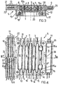
- FIG. 4 shows a plan view of the container of FIG. 2,
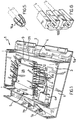
- FIG. 5 shows a partially cross sectioned perspective view of a detail of the container of FIG. 1, and
- FIG. 6 shows an exploded perspective view of another detail of the container of FIG. 1.
- With reference to the figures, reference number 1 indicates as a whole an active fibre optical amplifier having a
box shell 2 of essentially flattened parallelepiped form and with arectangular bottom 3 and side walls 4. On thebottom 3 is placed or directly formed an electronic card incorporating or supporting electric, electronic and electro-optical components of the amplifier including the pumping lasers. For drawing simplicity however said components are shown only summarily in the FIGS. because foreign to the present invention. Specifically a pumping laser 4a is shown. - The
shell 2 is mounted in turn on acard 5a incorporating additional electric components among which one or more multiconductor connectors. In addition, on thecard 5a are housed twooptical connectors - In the
shell 2 is mounted acontainer 5 for housing the optical components of the amplifier 1. Said components in the example shown comprise specifically anactive fibre 6, somecouplers 7, someoptical insulators 8, a twin-core filter 9 and somewelds 10 in addition naturally to the optical fibre lengths for connection of the various components (the so-called pigtails), all indicated by 11. Theelements fibre 6 which is active. It is noted that the number of components shown must not be considered representative of a specific optical circuit configuration. For the purposes of the present invention indeed the particular optical circuit provided with a number of optical components is irrelevant and in the FIGS. it is not sought to represent any specific optical circuit. - The
container 5 comprises four box elements and two covers all provided preferably in plastic material and constrained together in a removable manner so as to form a monolithic structure. - A
first box element 12 has an approximately parallelepiped form with four side walls opposed two by two and of which the twoopposed walls 13 supporting the optical elements extend in a direction X and twoopposed walls 14 for structural connection extend in a direction Y orthogonal to the direction X. - In the
box element 12 are provided side by side parallel seats for reception of the passiveoptical components grooves 15 formed in thewalls 13 in a direction Z perpendicular to the directions X and Y. Thegrooves 15 are open at one end (upper with reference to the FIGS.) and broken at the opposite end (lower with reference to the FIGS.). Each of thegrooves 15 on each of thewalls 13 is paired ideally with an equalcorresponding groove 15 formed on the other of thewalls 13 to form thus a seat for one or morepassive components box element 12 are therefore side by side and parallel. On the bottom of eachgroove 15 is formed aslot 16 for passage of thepigtail 11 of the components inserted in the seat. - The shape and dimensions of the
grooves 15 are determined by the shape and dimensions of the optical components to be inserted therein. Any differences, i.e. smaller components, can be compensated for with drilled elastic adapter caps 16a to be fitted on the component before insertion thereof in the grooves. Thecaps 16a also fulfil a useful shock absorbing function against any mechanical vibrations to protect the respective optical components. If very high shock absorption is required there can be provided specificshock absorbing blocks 16b in which the individual optical components are installed. - A
second box element 17 also approximately parallelepiped in shape has the form of a tray with flat bottom 18 andside walls 19 filleted together. In thebox element 17 is housed theactive fibre 6 arranged not on a spool but loose in the form of a skein lying on the bottom 18 and surrounded by thewalls 19. On the bottom 18 is provided acentral relief 20 functioning as a guide in the arrangement of the skein ofactive fibre 6. Thefibre 6 is not wound around therelief 20 but is only arranged around it loosely. In theside walls 19 are formedapertures 21 for passage of theactive fibre 6. - A
third box element 22 is also approximately parallelepiped in form and comprises a plurality of seats forwelds 10 arranged in two banks, to wit a first bank ofseats 23 side by side and a second bank ofseats 24 side by side. Theseats seats seats 23 and theseats 24 equal to approximately one half seat. - A
fourth box element 25 also approximately parallelepiped in shape comprises aspecial seat 26 specifically for an optical component not housable in the seats of thebox element 12. In the FIGS. is shown a flattenedseat 26 for housing a twin-core filter 9 with fouroutlet openings 27 for the fourpigtails 11 of thefilter 9. Thebox element 25 can be omitted where there are no special optical components requiring it. - The
box elements element 12 acts as a cover for theelement 17. Atrue cover 28 closes the top of thebox element 12. The mutual fixing of thebox elements cover 28 takes place by means of screws or equivalent. Thebox elements element 12 by means of dovetail tongue and groove coupling indicated by 29 and 30 respectively. Anothercover 31 is provided for the top closing of thebox element 22 fixed thereon by means of screws or equivalent. - Assembly of the active fibre optical amplifier 1 takes place as follows.
- First the
active fibre 6 is housed in thebox element 17 by setting it on the bottom 18 around therelief 20. Thepigtails 11 of theactive fibre 6 are passed outside thebox element 17 through theapertures 21. If the amplifier calls for multipleactive fibres 6 they can be housed in the same box element 17 (normally up to two) or in an additional identical box element superimposed on and constrained to thebox element 17. - Next are inserted the passive components (
couplers 7 and insulators 8) in thebox element 12 superimposed on thebox element 12. Each component is inserted in its seat formed by thegrooves 15 by mere traversing movement in the direction indicated by Z (vertical with reference to the FIGS.), hence perpendicular to the axis of said component. There are no particular problems in this step since each component is independent and free from the others. - At this point, if not already done, there are fixed the
box element 22 and optionally also thebox element 25 if any and in which are housed the specialoptical component 9. Even these operations both of fixing of thebox elements special component 9 take place by mere traversing of the parts in direction Z. - The step usually most difficult of the assembly is performance of the
welds 10 by means of a special machine, known and therefore not illustrated. For this purpose thecontainer 5 is positioned beside the welding machine and eachweld 10 performed is traversed in one of theseats seats pigtails 11 emerging from thewelds 10 inserted in theseats 23 pass with no need of bending through theseats 24 along a generatrix of thewelds 10 housed in saidseats 24 and vice versa. In the housing in the respective seats thewelds 10 are traversed in direction Z and hence perpendicularly to their own axis thus eliminating the risk of the optical fibres being subjected to axial traction which could be harmful. - In making the
welds 10 and arranging them in therespective seats pigtails 11 outside thecontainer 5 within thewalls 3 and 4 of theshell 2. - After completion of insertion of the various components the
container 5 is closed with thecovers - During the life of the amplifier 1 starting from the inspection step it may be necessary to do over some imperfect or damaged weld or to replace a defective optical component. In such cases the present invention is particularly useful and not only due to the rational arrangement which makes the individual components readily identifiable.
- Indeed, with the
covers container 5 by a simple movement in direction Z, i.e. perpendicular to the axis of the components. Such a movement induces neither axial traction nor bending stress on the optical fibres. Replacement operations are thus much easier and safer.
Claims (17)
- An active fibre optical amplifier (1) comprising a container (5), said container housing optical components within a shell (2) of the active fibre optical amplifier (1) with said components including at least one active fibre (6), a plurality of passive optical components (7, 8) and a plurality of welds (10) and in which the passive optical components (7, 8) and the welds (10) have an elongated cylindrical form with ends from which emerge lengths (11) of optical fibre and characterised by said container comprising:a first box element (12) for reception of the passive optical components (7, 8),a second box element (17) for reception of the active fibre (6), anda third box element (22) for reception of the welds (10) and in which the three box elements (12, 17, 22) are constrained in a removable manner to one another so as to form a monolithic structure of the container (5).
- Amplifier in accordance with claim 1 wherein in the first box element (12) are formed seats (15) side by side and parallel for insertion of each of the passive optical components (7, 8) in an insertion direction essentially orthogonal to the axis of said component (7, 8).
- Amplifier in accordance with claim 2 wherein the first box element (12) has four side walls (13, 14) opposed two by two and of which two opposing walls (13) supporting optical elements (7, 8) extending in a direction X and two opposing structural connecting walls (14) extending in direction Y orthogonal to direction X and each of the seats for the passive optical components (7, 8) comprising a pair of opposing grooves (15) formed in the supporting walls (13) and extending in direction Z orthogonal to the directions X and Y and slots (16) being provided in the bottom of the grooves (15) for passage of the optical fibre lengths (11) emerging from the passive optical components (7, 8).
- Amplifier in accordance with claim 3 wherein there are provided drilled elastic adapter caps (16a) between the passive optical components (7, 8) and the respective seats (15) with said caps (16a) fitted on the ends of the passive optical components (7, 8).
- Amplifier in accordance with claim 3 wherein in the seats (15) for the passive optical components (7, 8) are provided shock absorbing pads (16b) between which the passive optical components (7, 8) are laid.
- Amplifier in accordance with claim 1 wherein the second box element (17) is shaped like a tray with a flat bottom (18) and filleted side walls (19) for reception of at least one skein of loose active fibres (6).
- Amplifier in accordance with claim 6 wherein the bottom (18) is provided with a central relief (20).
- Amplifier in accordance with claim 1 wherein in the third box element (22) is formed at least one bank of seats (23, 24) side by side and parallel for insertion of each of the welds (10) in a direction of insertion essentially orthogonal to the axis of said weld (10).
- Amplifier in accordance with claim 8 wherein in the third box element (22) are formed two banks of coplanar seats (23, 24) butting one on another with offset equal to the breath of approximately one half seat between the seats (23) of one bank and the seats (24) of the other bank.
- Amplifier in accordance with any of the above claims wherein the first and the second box elements (12, 17) have similar external conformation and in the assembly of the container (5) the first box element (12) is mounted on the second box element (17) to close it.
- Amplifier in accordance with claim 10 wherein the third box element (22) is constrained laterally to the first and/or second box element (12, 17) by means of a grooved coupling (29).
- Amplifier in accordance with claim 11 wherein the first and the third box elements (12, 22) are closed by a respective cover (28, 31).
- Amplifier in accordance with claim 11 comprising a fourth box element (25) for reception of special optical components (9) and constrained laterally to the first and/or second box element (12, 17) by means of a grooved coupling (30) on the side opposite the third box element (22).
- An active fibre optical amplifier (1) comprising a container (5), said container housing passive optical components (7, 8) within a shell (2) of the active fibre optical amplifier (1) in which the passive optical components (7, 8) have an elongated cylindrical form with ends from which emerge optical fibre lengths (11) and characterised by said container comprising seats (15) side by side and parallel for the insertion of each of the passive optical components (7, 8) in an insertion direction essentially orthogonal to the axis of said component (7, 8).
- An active fibre optical amplifier (1) comprising a container (5), said container housing at least one loose active fibre (6) skein within a shell (2) of the active fibre optical amplifier (1) and characterised by said container comprising a box element (17) shaped like a tray with a flat bottom (18) and filleted side walls (19) for reception of said at least one loose active fibre (6) skein.
- An active fibre optical amplifier (1) comprising a container (5), said container housing welds (10) within a shell (2) of the active fibre optical amplifier (1) and in which the welds (10) have an elongated cylindrical form with ends from which emerge optical fibre lengths (11) and characterised by said container comprising at least one bank of seats (23, 24) side by side and parallel for insertion of each of the welds (10) in an insertion direction essentially orthogonal to the axis of said weld (10).
- Method of arrangement of components within a shell (2) of an active fibre optical amplifier (1) with said components including at least one active fibre (6),a plurality of passive optical components (7, 8) and a plurality of welds (10) and characterised by:housing the passive optical components (7, 8) in a first box element (12),housing the active fibre (6) in a second box element (17),housing the welds (10) in a third box element (22), andconstraining in a removable manner the three box elements (12, 17, 22) one to the other so as to form a monolithic container structure (5).
Applications Claiming Priority (2)
| Application Number | Priority Date | Filing Date | Title |
|---|---|---|---|
| ITMI942531 | 1994-12-15 | ||
| ITMI942531A IT1271281B (en) | 1994-12-15 | 1994-12-15 | CONTAINER FOR HOUSING OPTICAL COMPONENTS IN AN ACTIVE FIBER OPTIC AMPLIFIER |
Publications (2)
| Publication Number | Publication Date |
|---|---|
| EP0717479A1 EP0717479A1 (en) | 1996-06-19 |
| EP0717479B1 true EP0717479B1 (en) | 2003-02-19 |
Family
ID=11369998
Family Applications (1)
| Application Number | Title | Priority Date | Filing Date |
|---|---|---|---|
| EP95119608A Expired - Lifetime EP0717479B1 (en) | 1994-12-15 | 1995-12-13 | Active fiber optical amplifier comprising a container housing optical components |
Country Status (5)
| Country | Link |
|---|---|
| US (1) | US5668909A (en) |
| EP (1) | EP0717479B1 (en) |
| CA (1) | CA2165256A1 (en) |
| DE (1) | DE69529661T2 (en) |
| IT (1) | IT1271281B (en) |
Families Citing this family (16)
| Publication number | Priority date | Publication date | Assignee | Title |
|---|---|---|---|---|
| KR100242412B1 (en) * | 1996-10-25 | 2000-03-02 | 윤종용 | Packaging box for fixing optical element of optical fiber amplifier |
| US6269212B1 (en) * | 1997-09-18 | 2001-07-31 | Pirelli Cavi E Sistemi S.P.A. | Method for performing fixing inside a container for optical connection components |
| JP2000075145A (en) * | 1998-09-01 | 2000-03-14 | Fujitsu Ltd | Optical fiber holder |
| US6324331B1 (en) * | 1999-01-14 | 2001-11-27 | Corning Incorporated | Passive platform for holding optical components |
| US6418263B1 (en) * | 1999-01-28 | 2002-07-09 | Tyco Submarine Systems Ltd. | Method and apparatus for storing a fiber optic assembly |
| US6343761B1 (en) * | 1999-05-25 | 2002-02-05 | Tycom (Us) Inc. | Device for separating portions of spooled optical fibers |
| US6347760B1 (en) * | 1999-05-25 | 2002-02-19 | Tycom (Us) Inc. | Device for storing optical fibers |
| US6367730B1 (en) * | 1999-05-25 | 2002-04-09 | Tycom (Us) Inc. | Device for storing optical fibers |
| US6322019B1 (en) | 1999-09-08 | 2001-11-27 | Tycom (Us) Inc. | Device for covering a jacketed fiber storage space |
| US7532782B2 (en) * | 2002-04-18 | 2009-05-12 | Pivotal Decisions Llc | Flexible optical circuit apparatus and method |
| GB0327661D0 (en) * | 2003-11-28 | 2003-12-31 | Qinetiq Ltd | Optical Amplifier |
| NL2002522C2 (en) * | 2009-02-13 | 2010-08-16 | Attema Kunststoffenind | Optical fibre cable management in connection housing. |
| US9500832B2 (en) * | 2012-08-24 | 2016-11-22 | Kmt Innovations Llc | Optical fiber strand and splice sleeve retention tool for use during fiber optic cable splicing |
| WO2019148432A1 (en) * | 2018-02-01 | 2019-08-08 | 华为技术有限公司 | Optical cable connection apparatus |
| US10845561B1 (en) * | 2019-06-28 | 2020-11-24 | Afl Telecommunications Llc | Fiber optic cassettes and splice modules |
| CN110518444A (en) * | 2019-08-26 | 2019-11-29 | 上海禾赛光电科技有限公司 | Laser radar and its optical fiber laser |
Family Cites Families (12)
| Publication number | Priority date | Publication date | Assignee | Title |
|---|---|---|---|---|
| US4266853A (en) * | 1979-03-12 | 1981-05-12 | Northern Telecom Limited | Device for organizing optical fibers and the like |
| GB8729952D0 (en) * | 1987-12-23 | 1988-02-03 | British Telecomm | Mounting assembly for optical equipment |
| US4793681A (en) * | 1988-04-18 | 1988-12-27 | Gte Products Corporation | Splice cradle |
| US5071211A (en) * | 1988-12-20 | 1991-12-10 | Northern Telecom Limited | Connector holders and distribution frame and connector holder assemblies for optical cable |
| KR940001043B1 (en) * | 1989-07-20 | 1994-02-08 | 스미도모덴기고오교오 가부시기가이샤 | Fiber optic amplifier |
| JPH04106505A (en) * | 1990-08-27 | 1992-04-08 | Fujitsu Ltd | Packaging structure of internal unit of optical submarine repeater |
| WO1992022842A2 (en) * | 1991-06-18 | 1992-12-23 | British Telecommunications Public Limited Company | Optical fibre connection equipment |
| FR2687743B1 (en) * | 1992-02-21 | 1995-06-16 | Mars Actel | SET OF STACKED AND ARTICULATED MODULES. |
| US5383051A (en) * | 1992-10-30 | 1995-01-17 | Pirelli Cavi S.P.A. | Compact-size optical amplifier |
| US5323480A (en) * | 1992-11-25 | 1994-06-21 | Raychem Corporation | Fiber optic splice closure |
| US5353367A (en) * | 1993-11-29 | 1994-10-04 | Northern Telecom Limited | Distribution frame and optical connector holder combination |
| US5422974A (en) * | 1994-09-23 | 1995-06-06 | The United States Of America As Represented By The Secretary Of The Navy | Shock resistant optic fiber rotary splice holding device |
-
1994
- 1994-12-15 IT ITMI942531A patent/IT1271281B/en active IP Right Grant
-
1995
- 1995-12-05 US US08/567,493 patent/US5668909A/en not_active Expired - Fee Related
- 1995-12-13 EP EP95119608A patent/EP0717479B1/en not_active Expired - Lifetime
- 1995-12-13 DE DE69529661T patent/DE69529661T2/en not_active Expired - Fee Related
- 1995-12-14 CA CA002165256A patent/CA2165256A1/en not_active Abandoned
Also Published As
| Publication number | Publication date |
|---|---|
| DE69529661T2 (en) | 2003-10-16 |
| ITMI942531A1 (en) | 1996-06-15 |
| DE69529661D1 (en) | 2003-03-27 |
| IT1271281B (en) | 1997-05-27 |
| ITMI942531A0 (en) | 1994-12-15 |
| US5668909A (en) | 1997-09-16 |
| CA2165256A1 (en) | 1996-06-16 |
| EP0717479A1 (en) | 1996-06-19 |
Similar Documents
| Publication | Publication Date | Title |
|---|---|---|
| US5668909A (en) | Container for housing optical components in an active fiber optical amplifier | |
| CA2201985C (en) | Apparatus and method for housing optical components | |
| JP3138244B2 (en) | Optical fiber amplifier packaging structure | |
| US5646775A (en) | Compact-size optical amplifier having separate functions | |
| AU638254B2 (en) | Splice organiser | |
| US4886336A (en) | Storage device for a spare length of at least one optical fibre | |
| US5206927A (en) | Cassette and cassette block for light waveguides | |
| US6381394B1 (en) | Method and apparatus for assembling an amplifier assembly | |
| EP0370819B1 (en) | Fibre distribution arrangement | |
| EP0800246B1 (en) | Apparatus for housing high-heat-emission electrooptical components and method of assembling said apparatus | |
| WO2002039170A2 (en) | Multi-level optical fiber and component storage tray | |
| JPH04106505A (en) | Packaging structure of internal unit of optical submarine repeater | |
| JPH0763925A (en) | Optical unit structure | |
| WO2022254724A1 (en) | Wiring module, frame for wiring module, and method for preparing wiring module | |
| JP2713398B2 (en) | Optical fiber extra length storage device | |
| JP3010612B2 (en) | Optical fiber cable connection | |
| CN215641968U (en) | An optical cable junction box | |
| US6217227B1 (en) | Connecting device for optical fiber cables | |
| SE507117C2 (en) | Method and apparatus for splicing fiber optic cables | |
| US6418263B1 (en) | Method and apparatus for storing a fiber optic assembly | |
| JP2022163962A (en) | Wiring holding structure of optical fiber cable and optical communication device | |
| JPH0734045B2 (en) | Optical fiber extra length storage case | |
| JPH0256509A (en) | Optical fiber polarizer | |
| KR20020071332A (en) | An Optical fiber Surpporting plate having Sheet type for protecting |
Legal Events
| Date | Code | Title | Description |
|---|---|---|---|
| PUAI | Public reference made under article 153(3) epc to a published international application that has entered the european phase |
Free format text: ORIGINAL CODE: 0009012 |
|
| AK | Designated contracting states |
Kind code of ref document: A1 Designated state(s): DE ES FR GB IT |
|
| 17P | Request for examination filed |
Effective date: 19961209 |
|
| RAP1 | Party data changed (applicant data changed or rights of an application transferred) |
Owner name: PIRELLI CAVI E SISTEMI S.P.A. |
|
| 17Q | First examination report despatched |
Effective date: 19980630 |
|
| RAP1 | Party data changed (applicant data changed or rights of an application transferred) |
Owner name: OPTICAL TECHNOLOGIES U.S.A. CORP. |
|
| GRAG | Despatch of communication of intention to grant |
Free format text: ORIGINAL CODE: EPIDOS AGRA |
|
| RTI1 | Title (correction) |
Free format text: ACTIVE FIBER OPTICAL AMPLIFIER COMPRISING A CONTAINER HOUSING OPTICAL COMPONENTS |
|
| GRAG | Despatch of communication of intention to grant |
Free format text: ORIGINAL CODE: EPIDOS AGRA |
|
| GRAH | Despatch of communication of intention to grant a patent |
Free format text: ORIGINAL CODE: EPIDOS IGRA |
|
| GRAH | Despatch of communication of intention to grant a patent |
Free format text: ORIGINAL CODE: EPIDOS IGRA |
|
| GRAA | (expected) grant |
Free format text: ORIGINAL CODE: 0009210 |
|
| AK | Designated contracting states |
Designated state(s): DE ES FR GB IT |
|
| REG | Reference to a national code |
Ref country code: GB Ref legal event code: FG4D |
|
| REF | Corresponds to: |
Ref document number: 69529661 Country of ref document: DE Date of ref document: 20030327 Kind code of ref document: P |
|
| RAP2 | Party data changed (patent owner data changed or rights of a patent transferred) |
Owner name: CORNING O.T.I., INC. |
|
| RAP2 | Party data changed (patent owner data changed or rights of a patent transferred) |
Owner name: CORNING INCORPORATED |
|
| PG25 | Lapsed in a contracting state [announced via postgrant information from national office to epo] |
Ref country code: ES Free format text: LAPSE BECAUSE OF FAILURE TO SUBMIT A TRANSLATION OF THE DESCRIPTION OR TO PAY THE FEE WITHIN THE PRESCRIBED TIME-LIMIT Effective date: 20030828 |
|
| ET | Fr: translation filed | ||
| REG | Reference to a national code |
Ref country code: FR Ref legal event code: TP Ref country code: FR Ref legal event code: CD |
|
| PGFP | Annual fee paid to national office [announced via postgrant information from national office to epo] |
Ref country code: GB Payment date: 20031210 Year of fee payment: 9 |
|
| PGFP | Annual fee paid to national office [announced via postgrant information from national office to epo] |
Ref country code: FR Payment date: 20031218 Year of fee payment: 9 |
|
| PLBE | No opposition filed within time limit |
Free format text: ORIGINAL CODE: 0009261 |
|
| STAA | Information on the status of an ep patent application or granted ep patent |
Free format text: STATUS: NO OPPOSITION FILED WITHIN TIME LIMIT |
|
| REG | Reference to a national code |
Ref country code: GB Ref legal event code: 732E |
|
| RAP2 | Party data changed (patent owner data changed or rights of a patent transferred) |
Owner name: AVANEX CORPORATION |
|
| PGFP | Annual fee paid to national office [announced via postgrant information from national office to epo] |
Ref country code: DE Payment date: 20040202 Year of fee payment: 9 |
|
| 26N | No opposition filed |
Effective date: 20031120 |
|
| PG25 | Lapsed in a contracting state [announced via postgrant information from national office to epo] |
Ref country code: GB Free format text: LAPSE BECAUSE OF NON-PAYMENT OF DUE FEES Effective date: 20041213 |
|
| PG25 | Lapsed in a contracting state [announced via postgrant information from national office to epo] |
Ref country code: DE Free format text: LAPSE BECAUSE OF NON-PAYMENT OF DUE FEES Effective date: 20050701 |
|
| GBPC | Gb: european patent ceased through non-payment of renewal fee |
Effective date: 20041213 |
|
| PG25 | Lapsed in a contracting state [announced via postgrant information from national office to epo] |
Ref country code: FR Free format text: LAPSE BECAUSE OF NON-PAYMENT OF DUE FEES Effective date: 20050831 |
|
| REG | Reference to a national code |
Ref country code: FR Ref legal event code: ST |
|
| PG25 | Lapsed in a contracting state [announced via postgrant information from national office to epo] |
Ref country code: IT Free format text: LAPSE BECAUSE OF NON-PAYMENT OF DUE FEES;WARNING: LAPSES OF ITALIAN PATENTS WITH EFFECTIVE DATE BEFORE 2007 MAY HAVE OCCURRED AT ANY TIME BEFORE 2007. THE CORRECT EFFECTIVE DATE MAY BE DIFFERENT FROM THE ONE RECORDED. Effective date: 20051213 |