EP0716467A1 - Treatment of solid electrolytes to promote wettability - Google Patents
Treatment of solid electrolytes to promote wettability Download PDFInfo
- Publication number
- EP0716467A1 EP0716467A1 EP95118949A EP95118949A EP0716467A1 EP 0716467 A1 EP0716467 A1 EP 0716467A1 EP 95118949 A EP95118949 A EP 95118949A EP 95118949 A EP95118949 A EP 95118949A EP 0716467 A1 EP0716467 A1 EP 0716467A1
- Authority
- EP
- European Patent Office
- Prior art keywords
- asperity
- electrolyte
- filling metal
- sodium
- depositing
- Prior art date
- Legal status (The legal status is an assumption and is not a legal conclusion. Google has not performed a legal analysis and makes no representation as to the accuracy of the status listed.)
- Withdrawn
Links
- 239000007784 solid electrolyte Substances 0.000 title claims abstract description 24
- 239000003792 electrolyte Substances 0.000 claims abstract description 70
- DGAQECJNVWCQMB-PUAWFVPOSA-M Ilexoside XXIX Chemical compound C[C@@H]1CC[C@@]2(CC[C@@]3(C(=CC[C@H]4[C@]3(CC[C@@H]5[C@@]4(CC[C@@H](C5(C)C)OS(=O)(=O)[O-])C)C)[C@@H]2[C@]1(C)O)C)C(=O)O[C@H]6[C@@H]([C@H]([C@@H]([C@H](O6)CO)O)O)O.[Na+] DGAQECJNVWCQMB-PUAWFVPOSA-M 0.000 claims abstract description 53
- 229910052708 sodium Inorganic materials 0.000 claims abstract description 52
- 239000011734 sodium Substances 0.000 claims abstract description 52
- 229910052751 metal Inorganic materials 0.000 claims abstract description 40
- 239000002184 metal Substances 0.000 claims abstract description 40
- 238000000034 method Methods 0.000 claims abstract description 26
- 238000009736 wetting Methods 0.000 claims abstract description 25
- 239000007772 electrode material Substances 0.000 claims abstract description 20
- 239000007788 liquid Substances 0.000 claims abstract description 15
- PXHVJJICTQNCMI-UHFFFAOYSA-N Nickel Chemical compound [Ni] PXHVJJICTQNCMI-UHFFFAOYSA-N 0.000 claims description 56
- 229910052759 nickel Inorganic materials 0.000 claims description 27
- 238000000151 deposition Methods 0.000 claims description 14
- TWNQGVIAIRXVLR-UHFFFAOYSA-N oxo(oxoalumanyloxy)alumane Chemical compound O=[Al]O[Al]=O TWNQGVIAIRXVLR-UHFFFAOYSA-N 0.000 claims description 14
- 229910045601 alloy Inorganic materials 0.000 claims description 9
- 239000000956 alloy Substances 0.000 claims description 9
- 238000010438 heat treatment Methods 0.000 claims description 9
- RYGMFSIKBFXOCR-UHFFFAOYSA-N Copper Chemical compound [Cu] RYGMFSIKBFXOCR-UHFFFAOYSA-N 0.000 claims description 5
- 239000010949 copper Substances 0.000 claims description 5
- 229910052802 copper Inorganic materials 0.000 claims description 5
- 239000000843 powder Substances 0.000 claims description 5
- 229910001220 stainless steel Inorganic materials 0.000 claims description 3
- 239000002245 particle Substances 0.000 claims description 2
- 239000010935 stainless steel Substances 0.000 claims description 2
- 230000008018 melting Effects 0.000 abstract description 3
- 238000002844 melting Methods 0.000 abstract description 3
- 210000004027 cell Anatomy 0.000 description 43
- 210000000352 storage cell Anatomy 0.000 description 22
- NINIDFKCEFEMDL-UHFFFAOYSA-N Sulfur Chemical compound [S] NINIDFKCEFEMDL-UHFFFAOYSA-N 0.000 description 11
- BNOODXBBXFZASF-UHFFFAOYSA-N [Na].[S] Chemical compound [Na].[S] BNOODXBBXFZASF-UHFFFAOYSA-N 0.000 description 11
- 238000013459 approach Methods 0.000 description 11
- 229910052717 sulfur Inorganic materials 0.000 description 11
- 239000011593 sulfur Substances 0.000 description 11
- 229910021525 ceramic electrolyte Inorganic materials 0.000 description 6
- 230000000694 effects Effects 0.000 description 6
- 229910001415 sodium ion Inorganic materials 0.000 description 6
- 239000000919 ceramic Substances 0.000 description 5
- 229940046892 lead acetate Drugs 0.000 description 5
- 239000011324 bead Substances 0.000 description 4
- 230000008901 benefit Effects 0.000 description 4
- 239000000203 mixture Substances 0.000 description 4
- 229920001021 polysulfide Polymers 0.000 description 4
- 239000005077 polysulfide Substances 0.000 description 4
- 150000008117 polysulfides Polymers 0.000 description 4
- 230000009471 action Effects 0.000 description 3
- 238000013461 design Methods 0.000 description 3
- 229910052739 hydrogen Inorganic materials 0.000 description 3
- 239000001257 hydrogen Substances 0.000 description 3
- 230000008569 process Effects 0.000 description 3
- 229910000990 Ni alloy Inorganic materials 0.000 description 2
- 230000002411 adverse Effects 0.000 description 2
- PNEYBMLMFCGWSK-UHFFFAOYSA-N aluminium oxide Inorganic materials [O-2].[O-2].[O-2].[Al+3].[Al+3] PNEYBMLMFCGWSK-UHFFFAOYSA-N 0.000 description 2
- 238000011109 contamination Methods 0.000 description 2
- 238000009792 diffusion process Methods 0.000 description 2
- 230000007774 longterm Effects 0.000 description 2
- 230000002028 premature Effects 0.000 description 2
- 239000007787 solid Substances 0.000 description 2
- 238000012546 transfer Methods 0.000 description 2
- KEAYESYHFKHZAL-UHFFFAOYSA-N Sodium Chemical compound [Na] KEAYESYHFKHZAL-UHFFFAOYSA-N 0.000 description 1
- FKNQFGJONOIPTF-UHFFFAOYSA-N Sodium cation Chemical compound [Na+] FKNQFGJONOIPTF-UHFFFAOYSA-N 0.000 description 1
- 239000002253 acid Substances 0.000 description 1
- 239000007864 aqueous solution Substances 0.000 description 1
- 230000015572 biosynthetic process Effects 0.000 description 1
- OJIJEKBXJYRIBZ-UHFFFAOYSA-N cadmium nickel Chemical compound [Ni].[Cd] OJIJEKBXJYRIBZ-UHFFFAOYSA-N 0.000 description 1
- 229910010293 ceramic material Inorganic materials 0.000 description 1
- 230000008859 change Effects 0.000 description 1
- 238000006243 chemical reaction Methods 0.000 description 1
- 239000011248 coating agent Substances 0.000 description 1
- 238000000576 coating method Methods 0.000 description 1
- 230000000052 comparative effect Effects 0.000 description 1
- 230000001419 dependent effect Effects 0.000 description 1
- 230000008021 deposition Effects 0.000 description 1
- 238000011161 development Methods 0.000 description 1
- 238000010586 diagram Methods 0.000 description 1
- 238000007599 discharging Methods 0.000 description 1
- 238000006073 displacement reaction Methods 0.000 description 1
- 238000001035 drying Methods 0.000 description 1
- 239000002001 electrolyte material Substances 0.000 description 1
- 230000002708 enhancing effect Effects 0.000 description 1
- 239000011521 glass Substances 0.000 description 1
- 125000004435 hydrogen atom Chemical group [H]* 0.000 description 1
- FUJCRWPEOMXPAD-UHFFFAOYSA-N lithium oxide Chemical compound [Li+].[Li+].[O-2] FUJCRWPEOMXPAD-UHFFFAOYSA-N 0.000 description 1
- 229910001947 lithium oxide Inorganic materials 0.000 description 1
- 239000000463 material Substances 0.000 description 1
- 150000002739 metals Chemical class 0.000 description 1
- 238000012986 modification Methods 0.000 description 1
- 230000004048 modification Effects 0.000 description 1
- -1 nickel alloys Chemical class 0.000 description 1
- 229910000480 nickel oxide Inorganic materials 0.000 description 1
- GNRSAWUEBMWBQH-UHFFFAOYSA-N oxonickel Chemical compound [Ni]=O GNRSAWUEBMWBQH-UHFFFAOYSA-N 0.000 description 1
- 238000012545 processing Methods 0.000 description 1
- 238000009877 rendering Methods 0.000 description 1
- KKCBUQHMOMHUOY-UHFFFAOYSA-N sodium oxide Chemical compound [O-2].[Na+].[Na+] KKCBUQHMOMHUOY-UHFFFAOYSA-N 0.000 description 1
- 229910001948 sodium oxide Inorganic materials 0.000 description 1
- 239000000243 solution Substances 0.000 description 1
- 230000007480 spreading Effects 0.000 description 1
- 239000000126 substance Substances 0.000 description 1
- 238000012360 testing method Methods 0.000 description 1
- 230000000007 visual effect Effects 0.000 description 1
- XLYOFNOQVPJJNP-UHFFFAOYSA-N water Substances O XLYOFNOQVPJJNP-UHFFFAOYSA-N 0.000 description 1
Images
Classifications
-
- H—ELECTRICITY
- H01—ELECTRIC ELEMENTS
- H01M—PROCESSES OR MEANS, e.g. BATTERIES, FOR THE DIRECT CONVERSION OF CHEMICAL ENERGY INTO ELECTRICAL ENERGY
- H01M10/00—Secondary cells; Manufacture thereof
- H01M10/36—Accumulators not provided for in groups H01M10/05-H01M10/34
- H01M10/39—Accumulators not provided for in groups H01M10/05-H01M10/34 working at high temperature
- H01M10/3909—Sodium-sulfur cells
- H01M10/3918—Sodium-sulfur cells characterised by the electrolyte
-
- C—CHEMISTRY; METALLURGY
- C04—CEMENTS; CONCRETE; ARTIFICIAL STONE; CERAMICS; REFRACTORIES
- C04B—LIME, MAGNESIA; SLAG; CEMENTS; COMPOSITIONS THEREOF, e.g. MORTARS, CONCRETE OR LIKE BUILDING MATERIALS; ARTIFICIAL STONE; CERAMICS; REFRACTORIES; TREATMENT OF NATURAL STONE
- C04B41/00—After-treatment of mortars, concrete, artificial stone or ceramics; Treatment of natural stone
- C04B41/45—Coating or impregnating, e.g. injection in masonry, partial coating of green or fired ceramics, organic coating compositions for adhering together two concrete elements
- C04B41/50—Coating or impregnating, e.g. injection in masonry, partial coating of green or fired ceramics, organic coating compositions for adhering together two concrete elements with inorganic materials
- C04B41/51—Metallising, e.g. infiltration of sintered ceramic preforms with molten metal
-
- C—CHEMISTRY; METALLURGY
- C23—COATING METALLIC MATERIAL; COATING MATERIAL WITH METALLIC MATERIAL; CHEMICAL SURFACE TREATMENT; DIFFUSION TREATMENT OF METALLIC MATERIAL; COATING BY VACUUM EVAPORATION, BY SPUTTERING, BY ION IMPLANTATION OR BY CHEMICAL VAPOUR DEPOSITION, IN GENERAL; INHIBITING CORROSION OF METALLIC MATERIAL OR INCRUSTATION IN GENERAL
- C23C—COATING METALLIC MATERIAL; COATING MATERIAL WITH METALLIC MATERIAL; SURFACE TREATMENT OF METALLIC MATERIAL BY DIFFUSION INTO THE SURFACE, BY CHEMICAL CONVERSION OR SUBSTITUTION; COATING BY VACUUM EVAPORATION, BY SPUTTERING, BY ION IMPLANTATION OR BY CHEMICAL VAPOUR DEPOSITION, IN GENERAL
- C23C26/00—Coating not provided for in groups C23C2/00 - C23C24/00
-
- H—ELECTRICITY
- H01—ELECTRIC ELEMENTS
- H01M—PROCESSES OR MEANS, e.g. BATTERIES, FOR THE DIRECT CONVERSION OF CHEMICAL ENERGY INTO ELECTRICAL ENERGY
- H01M10/00—Secondary cells; Manufacture thereof
- H01M10/36—Accumulators not provided for in groups H01M10/05-H01M10/34
- H01M10/39—Accumulators not provided for in groups H01M10/05-H01M10/34 working at high temperature
- H01M10/3909—Sodium-sulfur cells
- H01M10/3945—Sodium-sulfur cells containing additives or special arrangements in the sodium compartment
-
- Y—GENERAL TAGGING OF NEW TECHNOLOGICAL DEVELOPMENTS; GENERAL TAGGING OF CROSS-SECTIONAL TECHNOLOGIES SPANNING OVER SEVERAL SECTIONS OF THE IPC; TECHNICAL SUBJECTS COVERED BY FORMER USPC CROSS-REFERENCE ART COLLECTIONS [XRACs] AND DIGESTS
- Y02—TECHNOLOGIES OR APPLICATIONS FOR MITIGATION OR ADAPTATION AGAINST CLIMATE CHANGE
- Y02E—REDUCTION OF GREENHOUSE GAS [GHG] EMISSIONS, RELATED TO ENERGY GENERATION, TRANSMISSION OR DISTRIBUTION
- Y02E60/00—Enabling technologies; Technologies with a potential or indirect contribution to GHG emissions mitigation
- Y02E60/10—Energy storage using batteries
Definitions
- This invention relates to electrolytic storage cells that utilize a solid electrolyte, and, more particularly, to the initial wetting of the electrode materials to the electrolyte.
- Rechargeable storage cells are electrochemical devices for storing and retaining an electrical charge and later delivering that charge as useful power.
- a number of such storage cells are typically connected together electrically to form a battery having specific voltage or current delivery capability.
- Familiar examples of the rechargeable storage cell are the lead-acid storage cell used in automobiles and the nickel-cadmium storage cell used in portable electronic devices such as cameras.
- Another type of storage cell having a greater storage capacity for its weight is the nickel oxide pressurized hydrogen cell, an important type of which is commonly called the nickel-hydrogen cell and is used in spacecraft applications.
- Yet another type of storage cell is the sodium-sulfur storage cell, which has been under development for over 20 years for use in a variety of terrestrial applications such as nonpolluting electric vehicles.
- the sodium-sulfur storage cell has the particular advantage that its storage capacity per unit weight of storage cell is several times the storage capacity of the nickel-hydrogen cell. The sodium-sulfur storage cell therefore is an attractive candidate for use in spacecraft applications as well as automotive applications.
- the sodium-sulfur electrolytic storage cell has an outer housing and a piece of an alumina-based ceramic within the outer housing.
- Sodium is placed into a first chamber defined on one side of the ceramic, and sulfur is placed into a second chamber on the other side of the ceramic.
- the storage cell is heated to a temperature of about 350 o C, at which temperature both the sodium and the sulfur are molten.
- the liquid sodium is the anode of the storage cell, the liquid sulfur is the cathode, and the solid ceramic is the electrolyte. Electrical energy is released when sodium ions diffuse through the ceramic into the sulfur, thereby forming sodium polysulfides. Electrical energy can be stored when the process is reversed during charging of the battery, with an applied voltage causing the sodium polysulfides to decompose to yield sodium and sulfur, and the sodium ions diffuse through the ceramic electrolyte back into the first chamber.
- planar cell One configuration of the sodium-sulfur cell is known as the "planar" cell.
- the term "planar” is used in this context to mean that the ceramic electrolyte is generally planar.
- Other configurations such as tubular forms having a cylindrical tubular electrolyte are also known.
- the planar design has the advantage that the active area of electrolyte is relatively larger per unit weight of cell than for a cylindrical design.
- Planar sodium-sulfur cells are disclosed in US Patents 3,765,945 and 3,783,024, for example.
- the electrolyte is exposed to lead acetate solution by coating the electrolyte with an aqueous solution of the lead acetate.
- Lead acetate deposited upon the electrolyte aids in achieving initial wetting when the lead acetate at the surface is reduced to lead in contact with the molten sodium of the cell.
- the aluminum oxide is sensitive to water, and therefore a drying step is required.
- the lead can be dissolved into the sodium during service, leading to long-term sodium-ion displacement in the aluminum oxide. This can result in localized strain within the electrolyte, leading to its premature failure.
- the lead acetate approach may also be unacceptable because of its slow reaction rate.
- the present invention fulfills this need, and further provides related advantages.
- the present invention provides an improved technique for rendering the ceramic electrolyte of an electrolytic storage cell more wettable by the molten electrode material. It is of specific applicability to improving the wettability of beta-double prime aluminum oxide by sodium. The approach is readily utilized without costly equipment and chemicals, and does not damage the electrolyte or contaminate the electrolytic cell. Wetting of the sodium to the electrolyte is achieved within a few minutes rather than in excess of 10 hours as in some prior approaches.
- a method of preparing a solid electrolyte of an electrolytic cell for wetting by a liquid electrode material comprises the steps of furnishing a solid electrolyte of an electrolytic cell and depositing an asperity-filling metal onto the surface of the solid electrolyte in an amount sufficient to fill surface asperities in the solid electrolyte.
- the method further includes heating the electrolyte and deposited asperity-filling metal to a temperature sufficient to melt a cell electrode material, and depositing an amount of the cell electrode material onto the electrolyte surface and permitting the liquid cell electrode material to wick along the surface of the electrolyte.
- a method of preparing a beta-double prime' aluminum oxide solid electrolyte for wetting by a liquid electrode material comprises the steps of furnishing a solid beta-double prime aluminum oxide electrolyte of an electrolytic cell and mechanically rubbing an asperity-filling metal such as nickel against the surface of the solid electrolyte until the solid electrolyte turns gray in color.
- the method further includes heating the electrolyte and deposited asperity-filling metal to a temperature above the melting point of sodium, depositing sodium onto the electrolyte surface, and permitting the liquid cell electrode material to wick along the surface of the electrolyte.
- the present approach is readily implemented by rubbing an asperity-filling metal such as nickel, copper, or a 300-series stainless steel onto the surface of the electrolyte.
- an asperity-filling metal such as nickel, copper, or a 300-series stainless steel
- nickel includes pure nickel and its alloys
- copper includes pure copper and its alloys, as long as the alloys in each case are sufficiently soft to permit their application to the surface of the electrolyte.
- Lead and its alloys may not be used as the asperity-filling metal.
- the asperity-filling material can be furnished as a powder, preferably less than 10 micrometers in diameter and most preferably from about 2 to about 3 micrometers in diameter.
- the asperity-filling metal can also be furnished in bulk form, such as a bar of metal rubbed against the surface of the electrolyte or a brush with bristles made of the metal.
- the asperity-filling metal is rubbed against the surface of the electrolyte until the surface asperities are filled. This condition may be judged by observing a change in the color of the surface from white to gray, in the case of beta-double prime aluminum oxide. This implementation is particularly attractive because it does not require complex application procedures and apparatus.
- the metal is simply rubbed onto the surface of the electrolyte.
- the electrolyte is heated to a temperature at which the metallic electrode material, sodium in the preferred case, is molten.
- a preferred initial heating temperature is about 150 o C.
- a bead of the sodium is melted onto the surface, forming a small molten ball.
- the temperature is then increased, preferably to about 265 o C, so that the sodium is wicked across the surface.
- the wettability-enhancing pretreatment is complete.
- the electrolyte is assembled into the electrolytic cell and loaded with the electrode materials, sodium and sulfur.
- the cell is ready for operation.
- the cell can be filled with the electrode materials prior to the heating and wicking steps, and the sodium electrode material will wet and wick along the surface of the electrolyte.
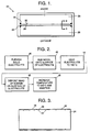
- FIG. 1 illustrates a simplified sodium-sulfur electrolytic storage cell 20, with which the present invention is preferably used.
- a planar cell is illustrated, but the present invention can be used with other configurations of cell.
- the electrolytic storage cell 20 includes a housing 22 in which the other components are sealed for operation.
- a planar piece of a ceramic electrolyte 24 divides the storage cell 20 into two parts, defining a first chamber 26 and a second chamber 28. This depiction shows the primary structural components of the cell 20, but design details not relevant to the present invention are omitted. Practical batteries are formed by combining a number of the illustrated cells in the appropriate electrically parallel or series configurations.
- the electrolyte 24 is a ceramic material that permits the rapid diffusion of sodium ions therethrough.
- the ceramic electrolyte 24 is beta-double prime alumina of a composition of about 90 percent aluminum oxide, 9 percent sodium oxide, and 1 percent lithium oxide. (All compositions herein are in percent by weight, unless otherwise indicated.)
- the electrolyte 16 is preferably less than 0.025 inches in thickness, more preferably is about 0.016 to about 0.020 inches in thickness, and most preferably is about 0.020 inches in thickness. The applicability of the present invention is not limited to any particular configuration, composition, or thickness of electrolyte, however.
- the electrolyte 24 is sealed to the inside of the wall of the container 22 using a glass seal 30, so that matter must pass through the electrolyte 24 to move between the chambers 26 and 28.
- Metallic sodium is loaded into the first chamber 26 and sulfur is placed into the second chamber 28.
- the storage cell is heated to a temperature of about 350 o C, at which temperature both the sodium and the sulfur are molten.
- the liquid sodium in the first chamber 26 is the anode of the storage cell
- the liquid sulfur in the second chamber 28 is the cathode.
- Electrical energy is released when sodium ions diffuse through the electrolyte 24 into the second chamber 28, thereby forming sodium polysulfides.
- Electrical energy can be stored when the process is reversed during charging of the cell 20, with an applied voltage causing the sodium polysulfides to decompose to yield sodium and sulfur, and the sodium ions diffuse from the second chamber 28 through the ceramic electrolyte 24 and back into the first chamber 26.
- metallic sodium contacts a surface 32 of the electrolyte 24 during operation of the cell 20. It is critical that the metallic sodium wet the surface 32, or diffusion of the sodium into the electrolyte 24 cannot occur.
- the most difficult aspect of wetting the electrolyte surface is achieving an initial wetting for the start-up of the cell 20. Once wetting is initially achieved, it will not be lost with continued operation of the cell.
- the present invention provides a method for improving the initial wettability of the surface 32 of the electrolyte 24, so that the sodium quickly wets the surface 32 even at initial contact and start-up of the cell 20.
- Figure 2 illustrates the preferred procedure for wettability enhancement and achieving wetting.
- Figure 3 illustrates the (greatly enlarged and magnified) profile of the surface 32 of the electrolyte 24, and the effect of the processing of the invention.
- the solid electrolyte 24 of the configuration, dimensions, and composition discussed previously is furnished, numeral 40.
- An asperity-filling metal such as nickel is rubbed onto the sodium-facing surface 32 of the electrolyte 24, numeral 42.
- Other relatively soft, abradable metals such as nickel alloys, copper and its alloys, and 300-series stainless steels can also be used. Lead and its alloys may not be used, and are therefore not within the scope of the term "asperity-filling metal", due to adverse effects on the operation and service life of the cell.
- the nickel or other asperity-filling metal is preferably provided as dry nickel powder having a reduced surface and of diameter less than about 10 micrometers, and preferably about 2-3 micrometers.
- the rubbing treatment is continued until the surface of the electrolyte 24 becomes gray in color, a visual indication of the transfer of metal to the surface.
- the rubbing action is best accomplished using a brush having nickel or nickel-alloy wire bristles and takes less than one minute for a typically sized electrolyte 24.
- the nickel fills in surface asperities (irregularities), as shown in Figure 3.
- surface asperities all surfaces such as the surface 32 have small asperities 34, such as roughness and pits, at the free surfaces. These asperities can interfere with the initial wetting of the surface with a liquid such as liquid sodium, inasmuch as they inhibit the spreading of a droplet. It is believed that the nickel fills in the asperities 32 so that an effectively smoother surface is presented. Sodium can therefore spread more readily on the surface by micro-bridging over the asperities.
- nickel is indicated at numeral 36 both in the asperities 34 and at the surface 32. This indication of the presence of nickel should not be interpreted as a continuous layer, although it is believed that nickel is present over most of the surface 32 after the rubbing treatment.
- the fine oxide containing the nickel particles at the surface is quite reactive with sodium and aids in accomplishing rapid wetting of the sodium to the treated surface.
- the nickel may be deposited by other techniques than rubbing. Rubbing is preferred, because the mechanical action preferentially deposits nickel into the asperities 34. Rubbing transfer of metal is also quick and easy to perform.
- the preferred source of the nickel is powder, as discussed. However, nickel may also be transferred from bulk nickel sources, such as a bar of nickel or a brush with nickel bristles. When the nickel is transferred from such a bulk source, care is required to avoid damaging the surface 32.
- the electrolyte is assembled into the cell 20.
- Sodium and sulfur are loaded into their respective compartments.
- the assembly is heated in vacuum to a temperature above the melting point of sodium, preferably about 150 o C, resulting in the formation of beads of sodium in contact with the surface 32 on the sodium side of the electrolyte.
- the beads of molten sodium form balls on the surface and do not initially spread along the surface.
- the temperature is increased to a higher temperature, preferably about 265 o C.
- the sodium balls spread spontaneously along the surface 32 by a wicking action.
- the wicking proceeds relatively quickly, and only about one minute or less is required to complete wetting.
- the progress of the wicking can be followed visually by the increased silvery appearance of the surface over which the molten sodium has spread. In practicing the invention with an actual cell, the surface is not visually accessible.
- the cell After the wettability enhancement treatment and initial wetting are complete, the cell is ready for service operation.
- a comparative study was performed to determine the effect of the pretreatment on wettability of the sodium to the electrolyte.
- a first piece of beta-double prime aluminum oxide electrolyte material was treated by rubbing a small amount of nickel powder having a diameter of 2-3 micrometers onto the surface of the electrolyte, until the surface changed from white to gray in color.
- the first electrolyte was heated to about 150 o C and a quantity of sodium metal was melted onto the surface to form a metal ball.
- the temperature was increased to about 265 o C.
- the sodium in the ball wicked along the nickel and thence the surface of the electrolyte. Progress of the wetting was observed visually by a darkening of the surface of the electrolyte.
- the same procedure was followed for a second piece of the beta-double prime aluminum oxide electrolyte, except that the second piece was not rubbed with nickel before heating.
- the first (treated) electrolyte exhibited a reduced surface resistivity of about 7 ohm-centimeters after 30 minutes, indicating wetting of the surface by the sodium. Achieving the same wetting required about 12 hours of heating in the case of the second (untreated) electrolyte.
- the present approach achieved a surface wetted by sodium much more quickly than observed for an untreated electrolyte surface. This faster wetting would be important in the case of an actual cell, to permit functioning of the charging/discharging cycle upon start-up of the cell.
- the present invention thus improves the wettability of solid electrolyte surfaces for use in electrolytic cells.
- the approach of the invention does not compromise long-term operation of the cell resulting from lead contamination to gain start-up wetting.
Landscapes
- Chemical & Material Sciences (AREA)
- Engineering & Computer Science (AREA)
- Organic Chemistry (AREA)
- Materials Engineering (AREA)
- Chemical Kinetics & Catalysis (AREA)
- Ceramic Engineering (AREA)
- Mechanical Engineering (AREA)
- Metallurgy (AREA)
- Manufacturing & Machinery (AREA)
- Electrochemistry (AREA)
- General Chemical & Material Sciences (AREA)
- Inorganic Chemistry (AREA)
- Structural Engineering (AREA)
- Secondary Cells (AREA)
Abstract
A solid electrolyte (24) is prepared for wetting by a liquid electrode material. The method includes mechanically rubbing an asperity-filling metal against the surface (32) of the solid electrolyte (24) until the solid electrolyte (24) turns gray in colour, which fills in asperities (34) in the surface (32) of the electrolyte (24). The electrolyte (24) and deposited asperity-filling metal (36) are heated to a temperature above the melting point of sodium, and sodium is deposited onto the electrolyte surface (32) and permitted to wick along the surface (32).
Description
- This invention relates to electrolytic storage cells that utilize a solid electrolyte, and, more particularly, to the initial wetting of the electrode materials to the electrolyte.
- Rechargeable storage cells are electrochemical devices for storing and retaining an electrical charge and later delivering that charge as useful power. A number of such storage cells are typically connected together electrically to form a battery having specific voltage or current delivery capability. Familiar examples of the rechargeable storage cell are the lead-acid storage cell used in automobiles and the nickel-cadmium storage cell used in portable electronic devices such as cameras. Another type of storage cell having a greater storage capacity for its weight is the nickel oxide pressurized hydrogen cell, an important type of which is commonly called the nickel-hydrogen cell and is used in spacecraft applications.
- Yet another type of storage cell is the sodium-sulfur storage cell, which has been under development for over 20 years for use in a variety of terrestrial applications such as nonpolluting electric vehicles. The sodium-sulfur storage cell has the particular advantage that its storage capacity per unit weight of storage cell is several times the storage capacity of the nickel-hydrogen cell. The sodium-sulfur storage cell therefore is an attractive candidate for use in spacecraft applications as well as automotive applications.
- In general, the sodium-sulfur electrolytic storage cell has an outer housing and a piece of an alumina-based ceramic within the outer housing. Sodium is placed into a first chamber defined on one side of the ceramic, and sulfur is placed into a second chamber on the other side of the ceramic. The storage cell is heated to a temperature of about 350oC, at which temperature both the sodium and the sulfur are molten. The liquid sodium is the anode of the storage cell, the liquid sulfur is the cathode, and the solid ceramic is the electrolyte. Electrical energy is released when sodium ions diffuse through the ceramic into the sulfur, thereby forming sodium polysulfides. Electrical energy can be stored when the process is reversed during charging of the battery, with an applied voltage causing the sodium polysulfides to decompose to yield sodium and sulfur, and the sodium ions diffuse through the ceramic electrolyte back into the first chamber.
- One configuration of the sodium-sulfur cell is known as the "planar" cell. The term "planar" is used in this context to mean that the ceramic electrolyte is generally planar. Other configurations such as tubular forms having a cylindrical tubular electrolyte are also known. The planar design has the advantage that the active area of electrolyte is relatively larger per unit weight of cell than for a cylindrical design. Planar sodium-sulfur cells are disclosed in US Patents 3,765,945 and 3,783,024, for example.
- One of the problems encountered in the use of sodium-sulfur cells, and particularly in relation to planar sodium-sulfur cells, is achieving initial wetting of the liquid sodium to the beta-double prime aluminum oxide electrolyte. The wetting angle of sodium to aluminum oxide is only about 90 degrees, and therefore the sodium does not easily wet and spread on the aluminum oxide. If wetting is not achieved, there may be start-up inconsistencies and uneven current densities at start-up of the cell. These effects may result in unsatisfactory performance of the electrolytic cell over extended periods of operation.
- There have been proposed several techniques for improving the initial wetting of the electrolyte by liquid sodium. In one, lead is deposited upon the electrolyte surface by autoabrasion. The use of the lead deposition approach can result in contamination of the electrolyte, particularly along its grain boundaries, leading to premature failure of the electrolyte during service.
- In another approach, the electrolyte is exposed to lead acetate solution by coating the electrolyte with an aqueous solution of the lead acetate. Lead acetate deposited upon the electrolyte aids in achieving initial wetting when the lead acetate at the surface is reduced to lead in contact with the molten sodium of the cell. However, the aluminum oxide is sensitive to water, and therefore a drying step is required. The lead can be dissolved into the sodium during service, leading to long-term sodium-ion displacement in the aluminum oxide. This can result in localized strain within the electrolyte, leading to its premature failure. The lead acetate approach may also be unacceptable because of its slow reaction rate.
- There is therefore a need for an improved approach to achieving wetting of the electrolyte by the electrode material, and specifically improving the wettability of aluminum oxide by sodium. The present invention fulfills this need, and further provides related advantages.
- The present invention provides an improved technique for rendering the ceramic electrolyte of an electrolytic storage cell more wettable by the molten electrode material. It is of specific applicability to improving the wettability of beta-double prime aluminum oxide by sodium. The approach is readily utilized without costly equipment and chemicals, and does not damage the electrolyte or contaminate the electrolytic cell. Wetting of the sodium to the electrolyte is achieved within a few minutes rather than in excess of 10 hours as in some prior approaches.
- In accordance with the invention, a method of preparing a solid electrolyte of an electrolytic cell for wetting by a liquid electrode material comprises the steps of furnishing a solid electrolyte of an electrolytic cell and depositing an asperity-filling metal onto the surface of the solid electrolyte in an amount sufficient to fill surface asperities in the solid electrolyte. The method further includes heating the electrolyte and deposited asperity-filling metal to a temperature sufficient to melt a cell electrode material, and depositing an amount of the cell electrode material onto the electrolyte surface and permitting the liquid cell electrode material to wick along the surface of the electrolyte.
- As applied to the preferred electrolyte for sodium-sulfur electrolytic storage cells, a method of preparing a beta-double prime' aluminum oxide solid electrolyte for wetting by a liquid electrode material comprises the steps of furnishing a solid beta-double prime aluminum oxide electrolyte of an electrolytic cell and mechanically rubbing an asperity-filling metal such as nickel against the surface of the solid electrolyte until the solid electrolyte turns gray in color. The method further includes heating the electrolyte and deposited asperity-filling metal to a temperature above the melting point of sodium, depositing sodium onto the electrolyte surface, and permitting the liquid cell electrode material to wick along the surface of the electrolyte.
- The present approach is readily implemented by rubbing an asperity-filling metal such as nickel, copper, or a 300-series stainless steel onto the surface of the electrolyte. (As sometimes used herein, "nickel" includes pure nickel and its alloys, and "copper" includes pure copper and its alloys, as long as the alloys in each case are sufficiently soft to permit their application to the surface of the electrolyte.) Lead and its alloys may not be used as the asperity-filling metal. The asperity-filling material can be furnished as a powder, preferably less than 10 micrometers in diameter and most preferably from about 2 to about 3 micrometers in diameter. The asperity-filling metal can also be furnished in bulk form, such as a bar of metal rubbed against the surface of the electrolyte or a brush with bristles made of the metal.
- The asperity-filling metal is rubbed against the surface of the electrolyte until the surface asperities are filled. This condition may be judged by observing a change in the color of the surface from white to gray, in the case of beta-double prime aluminum oxide. This implementation is particularly attractive because it does not require complex application procedures and apparatus. The metal is simply rubbed onto the surface of the electrolyte.
- After the asperity-filling metal is transferred to the surface of the electrolyte, the electrolyte is heated to a temperature at which the metallic electrode material, sodium in the preferred case, is molten. A preferred initial heating temperature is about 150oC. A bead of the sodium is melted onto the surface, forming a small molten ball. The temperature is then increased, preferably to about 265oC, so that the sodium is wicked across the surface.
- The wettability-enhancing pretreatment is complete. The electrolyte is assembled into the electrolytic cell and loaded with the electrode materials, sodium and sulfur. The cell is ready for operation. Alternatively, the cell can be filled with the electrode materials prior to the heating and wicking steps, and the sodium electrode material will wet and wick along the surface of the electrolyte.
- This approach improves the wettability of the electrode of a solid-electrolyte cell, so that it achieves start up quickly and without adverse effects. The sodium-facing surface of the electrolyte is completely wetted by the sodium from the start. Other features and advantages of the present invention will be apparent from the following more detailed description of the preferred embodiment, taken in conjunction with the accompanying drawings, which illustrate, by way of example, the principles of the invention.
-
- Figure 1 is a schematic view of a planar sodium-sulfur electrolytic cell;
- Figure 2 is a process flow diagram for a preferred approach to enhancing the wettability of the electrolyte; and
- Figure 3 is an enlarged, idealized schematic view of the electrolyte of the electrolytic cell of Figure 1, taken along line 3-3.
- Figure 1 illustrates a simplified sodium-sulfur
electrolytic storage cell 20, with which the present invention is preferably used. A planar cell is illustrated, but the present invention can be used with other configurations of cell. Theelectrolytic storage cell 20 includes ahousing 22 in which the other components are sealed for operation. A planar piece of aceramic electrolyte 24 divides thestorage cell 20 into two parts, defining afirst chamber 26 and asecond chamber 28. This depiction shows the primary structural components of thecell 20, but design details not relevant to the present invention are omitted. Practical batteries are formed by combining a number of the illustrated cells in the appropriate electrically parallel or series configurations. - The
electrolyte 24 is a ceramic material that permits the rapid diffusion of sodium ions therethrough. In its most preferred form, theceramic electrolyte 24 is beta-double prime alumina of a composition of about 90 percent aluminum oxide, 9 percent sodium oxide, and 1 percent lithium oxide. (All compositions herein are in percent by weight, unless otherwise indicated.) The electrolyte 16 is preferably less than 0.025 inches in thickness, more preferably is about 0.016 to about 0.020 inches in thickness, and most preferably is about 0.020 inches in thickness. The applicability of the present invention is not limited to any particular configuration, composition, or thickness of electrolyte, however. Theelectrolyte 24 is sealed to the inside of the wall of thecontainer 22 using aglass seal 30, so that matter must pass through theelectrolyte 24 to move between thechambers - Metallic sodium is loaded into the
first chamber 26 and sulfur is placed into thesecond chamber 28. In operation, the storage cell is heated to a temperature of about 350oC, at which temperature both the sodium and the sulfur are molten. The liquid sodium in thefirst chamber 26 is the anode of the storage cell, the liquid sulfur in thesecond chamber 28 is the cathode. Electrical energy is released when sodium ions diffuse through theelectrolyte 24 into thesecond chamber 28, thereby forming sodium polysulfides. Electrical energy can be stored when the process is reversed during charging of thecell 20, with an applied voltage causing the sodium polysulfides to decompose to yield sodium and sulfur, and the sodium ions diffuse from thesecond chamber 28 through theceramic electrolyte 24 and back into thefirst chamber 26. - Thus, metallic sodium contacts a
surface 32 of theelectrolyte 24 during operation of thecell 20. It is critical that the metallic sodium wet thesurface 32, or diffusion of the sodium into theelectrolyte 24 cannot occur. The most difficult aspect of wetting the electrolyte surface is achieving an initial wetting for the start-up of thecell 20. Once wetting is initially achieved, it will not be lost with continued operation of the cell. - The present invention provides a method for improving the initial wettability of the
surface 32 of theelectrolyte 24, so that the sodium quickly wets thesurface 32 even at initial contact and start-up of thecell 20. Figure 2 illustrates the preferred procedure for wettability enhancement and achieving wetting. Figure 3 illustrates the (greatly enlarged and magnified) profile of thesurface 32 of theelectrolyte 24, and the effect of the processing of the invention. - Referring to Figure 2, the
solid electrolyte 24 of the configuration, dimensions, and composition discussed previously is furnished, numeral 40. An asperity-filling metal such as nickel is rubbed onto the sodium-facingsurface 32 of theelectrolyte 24,numeral 42. Other relatively soft, abradable metals such as nickel alloys, copper and its alloys, and 300-series stainless steels can also be used. Lead and its alloys may not be used, and are therefore not within the scope of the term "asperity-filling metal", due to adverse effects on the operation and service life of the cell. - The nickel or other asperity-filling metal is preferably provided as dry nickel powder having a reduced surface and of diameter less than about 10 micrometers, and preferably about 2-3 micrometers. The rubbing treatment is continued until the surface of the
electrolyte 24 becomes gray in color, a visual indication of the transfer of metal to the surface. The rubbing action is best accomplished using a brush having nickel or nickel-alloy wire bristles and takes less than one minute for a typicallysized electrolyte 24. - The following explanation of the effect of the nickel placed onto the surface is believed to be correct. However, the operability of the invention is not dependent upon any particular explanation of the invention. It is believed that the nickel fills in surface asperities (irregularities), as shown in Figure 3. Generally, all surfaces such as the
surface 32 havesmall asperities 34, such as roughness and pits, at the free surfaces. These asperities can interfere with the initial wetting of the surface with a liquid such as liquid sodium, inasmuch as they inhibit the spreading of a droplet. It is believed that the nickel fills in theasperities 32 so that an effectively smoother surface is presented. Sodium can therefore spread more readily on the surface by micro-bridging over the asperities. In Figure 3, nickel is indicated at numeral 36 both in theasperities 34 and at thesurface 32. This indication of the presence of nickel should not be interpreted as a continuous layer, although it is believed that nickel is present over most of thesurface 32 after the rubbing treatment. The fine oxide containing the nickel particles at the surface is quite reactive with sodium and aids in accomplishing rapid wetting of the sodium to the treated surface. - The nickel may be deposited by other techniques than rubbing. Rubbing is preferred, because the mechanical action preferentially deposits nickel into the
asperities 34. Rubbing transfer of metal is also quick and easy to perform. The preferred source of the nickel is powder, as discussed. However, nickel may also be transferred from bulk nickel sources, such as a bar of nickel or a brush with nickel bristles. When the nickel is transferred from such a bulk source, care is required to avoid damaging thesurface 32. - After the nickel has been transferred to the
surface 32, the electrolyte is assembled into thecell 20. Sodium and sulfur are loaded into their respective compartments. The assembly is heated in vacuum to a temperature above the melting point of sodium, preferably about 150oC, resulting in the formation of beads of sodium in contact with thesurface 32 on the sodium side of the electrolyte. The beads of molten sodium form balls on the surface and do not initially spread along the surface. Once the beads are in place, the temperature is increased to a higher temperature, preferably about 265oC. At this temperature, the sodium balls spread spontaneously along thesurface 32 by a wicking action. The wicking proceeds relatively quickly, and only about one minute or less is required to complete wetting. When testing is performed, the progress of the wicking can be followed visually by the increased silvery appearance of the surface over which the molten sodium has spread. In practicing the invention with an actual cell, the surface is not visually accessible. - After the wettability enhancement treatment and initial wetting are complete, the cell is ready for service operation.
- A comparative study was performed to determine the effect of the pretreatment on wettability of the sodium to the electrolyte. A first piece of beta-double prime aluminum oxide electrolyte material was treated by rubbing a small amount of nickel powder having a diameter of 2-3 micrometers onto the surface of the electrolyte, until the surface changed from white to gray in color. The first electrolyte was heated to about 150oC and a quantity of sodium metal was melted onto the surface to form a metal ball. The temperature was increased to about 265oC. The sodium in the ball wicked along the nickel and thence the surface of the electrolyte. Progress of the wetting was observed visually by a darkening of the surface of the electrolyte. The same procedure was followed for a second piece of the beta-double prime aluminum oxide electrolyte, except that the second piece was not rubbed with nickel before heating.
- The first (treated) electrolyte exhibited a reduced surface resistivity of about 7 ohm-centimeters after 30 minutes, indicating wetting of the surface by the sodium. Achieving the same wetting required about 12 hours of heating in the case of the second (untreated) electrolyte. Thus, the present approach achieved a surface wetted by sodium much more quickly than observed for an untreated electrolyte surface. This faster wetting would be important in the case of an actual cell, to permit functioning of the charging/discharging cycle upon start-up of the cell.
- The present invention thus improves the wettability of solid electrolyte surfaces for use in electrolytic cells. The approach of the invention does not compromise long-term operation of the cell resulting from lead contamination to gain start-up wetting. Although a particular embodiment of the invention has been described in detail for purposes of illustration, various modifications may be made without departing from the spirit and scope of the invention. Accordingly, the invention is not to be limited except as by the appended claims.
Claims (11)
- A method of preparing a solid electrolyte (24) of an electrolytic cell (20) for wetting by a liquid electrode material, comprising the step of furnishing the solid electrolyte (24) of the electrolytic cell (20), characterized by the further steps of:- depositing an asperity-filling metal (36) on a surface (32) of the solid electrolyte (24) in an amount sufficient to fill surface asperities (34) in the solid electrolyte (24);- heating the electrolyte (24) and deposited asperity-filling metal (36) to a first predetermined temperature, preferably sufficient to melt a cell electrode material; and- depositing a quantity of the cell electrode material onto the electrolyte surface (32) upon which the asperity-filling metal (36) has been deposited, and permitting the liquid cell electrode material to wick along the surface (32) of the electrolyte (24).
- The method of claim 1, characterized in that the step of furnishing a solid electrolyte (24) includes the step of furnishing beta-double prime aluminum oxide as the solid electrolyte (24).
- The method of claim 1 or 2, characterized in that the step of depositing an asperity-filling metal (36) includes the step of rubbing, preferably mechanically rubbing, the asperity-filling metal (36) onto the surface (32).
- The method of claim 3, characterized in that the step of rubbing the metal (36) includes the step of rubbing the metal (36) until the surface (32) of the solid electrolyte (24) turns gray in colour.
- The method of any of claims 1 - 4, characterized in that the step of depositing an asperity-filling metal (36) includes the steps of:- furnishing a piece of bulk asperity-filling metal (36); and- rubbing the piece of bulk asperity-filling metal (36) against the surface (32) of the electrolyte (24).
- The method of any of claims 1 - 3, characterized in that the step of depositing an asperity-filling metal (36) includes the step of rubbing asperity-filling metal powder onto the surface (32).
- The method of claim 6, characterized in that the step of rubbing asperity-filling metal powder includes the step of providing asperity-filling metal powder with a particle size of from about 2 to about 3 micrometers.
- The method of any of claims 1 - 7, characterized in that the step of depositing an asperity-filling metal (36) includes the step of providing an asperity-filling metal (36) selected from the group consisting of nickel and its alloys, copper and its alloys, and 300-series stainless steel, but not lead and its alloys.
- The method of any of claims 1 - 7, characterized in that the step of depositing an asperity-filling metal (36) includes the step of providing nickel as the asperity-filling metal (36).
- The method of any of claims 1 - 9, characterized in that the step of depositing a quantity of the cell electrode material includes the step of providing sodium as the cell electrode material.
- The method of any of claims 1 - 10, characterized in that the step of heating and depositing includes the steps of:- heating the electrolyte (24) and deposited asperity-filling metal (36) to a temperature of about 150 °C;- depositing sodium on the surface (32) of the solid electrolyte (24); and- increasing the temperature of the electrolyte (24) to about 265 °C and maintaining the temperature for a time sufficient to permit the molten sodium to wick across the surface (32) of the solid electrolyte (24).
Applications Claiming Priority (2)
| Application Number | Priority Date | Filing Date | Title |
|---|---|---|---|
| US350304 | 1989-05-11 | ||
| US08/350,304 US5554411A (en) | 1994-12-06 | 1994-12-06 | Treatment of solid electrolytes to promote wettability |
Publications (1)
| Publication Number | Publication Date |
|---|---|
| EP0716467A1 true EP0716467A1 (en) | 1996-06-12 |
Family
ID=23376130
Family Applications (1)
| Application Number | Title | Priority Date | Filing Date |
|---|---|---|---|
| EP95118949A Withdrawn EP0716467A1 (en) | 1994-12-06 | 1995-12-01 | Treatment of solid electrolytes to promote wettability |
Country Status (3)
| Country | Link |
|---|---|
| US (1) | US5554411A (en) |
| EP (1) | EP0716467A1 (en) |
| JP (1) | JPH08227727A (en) |
Cited By (1)
| Publication number | Priority date | Publication date | Assignee | Title |
|---|---|---|---|---|
| CN119833567A (en) * | 2024-12-13 | 2025-04-15 | 上海交通大学 | Solid-state battery anode material, and preparation method and application thereof |
Families Citing this family (1)
| Publication number | Priority date | Publication date | Assignee | Title |
|---|---|---|---|---|
| JP4107282B2 (en) * | 2004-10-15 | 2008-06-25 | 日産自動車株式会社 | Thermal spraying pretreatment method, engine cylinder block, and thermal spraying pretreatment device |
Citations (8)
| Publication number | Priority date | Publication date | Assignee | Title |
|---|---|---|---|---|
| US3765945A (en) | 1970-12-01 | 1973-10-16 | British Railways Board | Electric cells and batteries |
| US3783924A (en) | 1972-02-07 | 1974-01-08 | Rockland Ind Ltd | Replacement tread band for retreading a worn tire |
| FR2309052A1 (en) * | 1975-04-24 | 1976-11-19 | British Railways Board | Alkali metal and sulphur battery cell - has outer tubular case and has inner tubular solid electrolyte which is used for representing cathode space (NL261076) |
| EP0152204A2 (en) * | 1984-01-24 | 1985-08-21 | Tribohesion Limited | Coating process |
| GB2195329A (en) * | 1986-09-25 | 1988-04-07 | Lilliwyte Sa | Method of preparing ceramic surfaces for wetting thereof by alkali metals |
| WO1990001808A1 (en) * | 1988-08-10 | 1990-02-22 | Licentia Patent-Verwaltungs-Gmbh | Process for bonding a superconductor |
| WO1991010757A1 (en) * | 1990-01-16 | 1991-07-25 | Etienne Broult | Method and apparatus for depositing on a solid substrate a solid additive material consisting of particles of at least one metal, alloy or metalloid |
| USH971H (en) * | 1988-10-24 | 1991-10-01 | The United States Of America As Represented By The Secretary Of The Air Force | Regidized porous material and method |
Family Cites Families (4)
| Publication number | Priority date | Publication date | Assignee | Title |
|---|---|---|---|---|
| GB1344069A (en) * | 1970-11-24 | 1974-01-16 | British Railways Board | Electric cells and batteries |
| US4183137A (en) * | 1977-02-15 | 1980-01-15 | Lomerson Robert B | Method for metalizing holes in insulation material |
| US4348468A (en) * | 1979-12-28 | 1982-09-07 | Chloride Silent Power Limited | Beta alumina solid electrolyte material and its manufacture and electrochemical cells or other energy conversion devices containing such material |
| JPH044573A (en) * | 1990-04-23 | 1992-01-09 | Hitachi Ltd | Na-s secondary battery |
-
1994
- 1994-12-06 US US08/350,304 patent/US5554411A/en not_active Expired - Fee Related
-
1995
- 1995-12-01 EP EP95118949A patent/EP0716467A1/en not_active Withdrawn
- 1995-12-06 JP JP7318420A patent/JPH08227727A/en active Pending
Patent Citations (8)
| Publication number | Priority date | Publication date | Assignee | Title |
|---|---|---|---|---|
| US3765945A (en) | 1970-12-01 | 1973-10-16 | British Railways Board | Electric cells and batteries |
| US3783924A (en) | 1972-02-07 | 1974-01-08 | Rockland Ind Ltd | Replacement tread band for retreading a worn tire |
| FR2309052A1 (en) * | 1975-04-24 | 1976-11-19 | British Railways Board | Alkali metal and sulphur battery cell - has outer tubular case and has inner tubular solid electrolyte which is used for representing cathode space (NL261076) |
| EP0152204A2 (en) * | 1984-01-24 | 1985-08-21 | Tribohesion Limited | Coating process |
| GB2195329A (en) * | 1986-09-25 | 1988-04-07 | Lilliwyte Sa | Method of preparing ceramic surfaces for wetting thereof by alkali metals |
| WO1990001808A1 (en) * | 1988-08-10 | 1990-02-22 | Licentia Patent-Verwaltungs-Gmbh | Process for bonding a superconductor |
| USH971H (en) * | 1988-10-24 | 1991-10-01 | The United States Of America As Represented By The Secretary Of The Air Force | Regidized porous material and method |
| WO1991010757A1 (en) * | 1990-01-16 | 1991-07-25 | Etienne Broult | Method and apparatus for depositing on a solid substrate a solid additive material consisting of particles of at least one metal, alloy or metalloid |
Non-Patent Citations (1)
| Title |
|---|
| PATENT ABSTRACTS OF JAPAN vol. 16, no. 146 (E - 1188) 10 April 1992 (1992-04-10) * |
Cited By (1)
| Publication number | Priority date | Publication date | Assignee | Title |
|---|---|---|---|---|
| CN119833567A (en) * | 2024-12-13 | 2025-04-15 | 上海交通大学 | Solid-state battery anode material, and preparation method and application thereof |
Also Published As
| Publication number | Publication date |
|---|---|
| JPH08227727A (en) | 1996-09-03 |
| US5554411A (en) | 1996-09-10 |
Similar Documents
| Publication | Publication Date | Title |
|---|---|---|
| US6730441B1 (en) | Rechargeable electrochemical cell | |
| US3969139A (en) | Lithium electrode and an electrical energy storage device containing the same | |
| US4048395A (en) | Lithium electrode for electrical energy storage device | |
| CA1084586A (en) | Negative electrode of lithium, silicon and boron for electrochemical cells | |
| CN103636056B (en) | Manufacturing method of molten salt battery and molten salt battery | |
| FR2721140A1 (en) | Electrochemical accumulator element, cathode for such an element and their manufacturing processes. | |
| JPS618850A (en) | Dense anode of lithium alloy for full solid battery | |
| JP3172201B2 (en) | Rechargeable high temperature electrochemical power storage battery | |
| KR102144284B1 (en) | Solid electrolyte structures, sodium secondary battery including the same, and method for treating surfaces of the solid electrolyte | |
| CN107068964A (en) | Lithium aluminum alloy surface modified lithium cathode and solid-state battery thereof | |
| CA1045680A (en) | Lithium-silicon electrode for rechargeable cell | |
| US3881951A (en) | Lithium electrode and method of producing the same | |
| CA1065013A (en) | Method of preparing an electrochemical cell in uncharged state | |
| US5554411A (en) | Treatment of solid electrolytes to promote wettability | |
| JPH09270273A (en) | Polysulfide and carbon electrode materials and related methods | |
| JPH0463509B2 (en) | ||
| Scrosati et al. | Electrochemical Properties of RbAg4 I 5 Solid Electrolyte: II. Study of Silver Electrode Reversibility | |
| JPS58155668A (en) | Molten-salt fuel cell | |
| US3844842A (en) | Insulating seal for molten salt battery | |
| KR20070108761A (en) | Lithium Secondary Battery Formation Method | |
| GB2105512A (en) | A battery and method of making the battery | |
| US4360578A (en) | Method of enhancing the wettability of boron nitride for use as an electrochemical cell separator | |
| EP0855753A1 (en) | Special lead alloy containing antimomy and tin and positive electrode grid for use in lead-acid accumulator having improved corrosion resistance at high temperatures | |
| KR102847584B1 (en) | Manufacturing method of thermocell cathode using capillary phenomenon and thermocell cathode manufactured by the method | |
| Singh et al. | Role of electrolyte-sodium interface behavior to the degradation of a sodium-sulfur cell |
Legal Events
| Date | Code | Title | Description |
|---|---|---|---|
| PUAI | Public reference made under article 153(3) epc to a published international application that has entered the european phase |
Free format text: ORIGINAL CODE: 0009012 |
|
| AK | Designated contracting states |
Kind code of ref document: A1 Designated state(s): DE GB |
|
| 17P | Request for examination filed |
Effective date: 19961205 |
|
| 17Q | First examination report despatched |
Effective date: 19981006 |
|
| STAA | Information on the status of an ep patent application or granted ep patent |
Free format text: STATUS: THE APPLICATION IS DEEMED TO BE WITHDRAWN |
|
| 18D | Application deemed to be withdrawn |
Effective date: 19990217 |