EP0715397B1 - Switched reluctance motor - Google Patents
Switched reluctance motor Download PDFInfo
- Publication number
- EP0715397B1 EP0715397B1 EP95118683A EP95118683A EP0715397B1 EP 0715397 B1 EP0715397 B1 EP 0715397B1 EP 95118683 A EP95118683 A EP 95118683A EP 95118683 A EP95118683 A EP 95118683A EP 0715397 B1 EP0715397 B1 EP 0715397B1
- Authority
- EP
- European Patent Office
- Prior art keywords
- rotor
- poles
- motor
- pole
- reluctance
- Prior art date
- Legal status (The legal status is an assumption and is not a legal conclusion. Google has not performed a legal analysis and makes no representation as to the accuracy of the status listed.)
- Expired - Lifetime
Links
- 230000005291 magnetic effect Effects 0.000 claims abstract description 40
- 238000006073 displacement reaction Methods 0.000 claims 1
- 230000004907 flux Effects 0.000 description 12
- 230000005284 excitation Effects 0.000 description 11
- 239000000696 magnetic material Substances 0.000 description 5
- 230000008878 coupling Effects 0.000 description 4
- 238000010168 coupling process Methods 0.000 description 4
- 238000005859 coupling reaction Methods 0.000 description 4
- 239000000463 material Substances 0.000 description 4
- QJVKUMXDEUEQLH-UHFFFAOYSA-N [B].[Fe].[Nd] Chemical compound [B].[Fe].[Nd] QJVKUMXDEUEQLH-UHFFFAOYSA-N 0.000 description 3
- 229910045601 alloy Inorganic materials 0.000 description 3
- 239000000956 alloy Substances 0.000 description 3
- KPLQYGBQNPPQGA-UHFFFAOYSA-N cobalt samarium Chemical compound [Co].[Sm] KPLQYGBQNPPQGA-UHFFFAOYSA-N 0.000 description 3
- 229910001172 neodymium magnet Inorganic materials 0.000 description 3
- 229910000938 samarium–cobalt magnet Inorganic materials 0.000 description 3
- 230000002123 temporal effect Effects 0.000 description 3
- XEEYBQQBJWHFJM-UHFFFAOYSA-N Iron Chemical compound [Fe] XEEYBQQBJWHFJM-UHFFFAOYSA-N 0.000 description 2
- 230000005347 demagnetization Effects 0.000 description 2
- 230000000694 effects Effects 0.000 description 2
- 230000005611 electricity Effects 0.000 description 2
- 230000002427 irreversible effect Effects 0.000 description 2
- 238000010587 phase diagram Methods 0.000 description 2
- 239000003637 basic solution Substances 0.000 description 1
- 230000008901 benefit Effects 0.000 description 1
- 230000008859 change Effects 0.000 description 1
- 239000001177 diphosphate Substances 0.000 description 1
- 238000005265 energy consumption Methods 0.000 description 1
- 230000002349 favourable effect Effects 0.000 description 1
- 230000005294 ferromagnetic effect Effects 0.000 description 1
- 229910052742 iron Inorganic materials 0.000 description 1
- 238000004519 manufacturing process Methods 0.000 description 1
- 238000005259 measurement Methods 0.000 description 1
- 238000012986 modification Methods 0.000 description 1
- 230000004048 modification Effects 0.000 description 1
- 238000005457 optimization Methods 0.000 description 1
- 238000011084 recovery Methods 0.000 description 1
- 230000009467 reduction Effects 0.000 description 1
- 239000000243 solution Substances 0.000 description 1
Images


Classifications
-
- H—ELECTRICITY
- H02—GENERATION; CONVERSION OR DISTRIBUTION OF ELECTRIC POWER
- H02K—DYNAMO-ELECTRIC MACHINES
- H02K16/00—Machines with more than one rotor or stator
- H02K16/02—Machines with one stator and two or more rotors
-
- H—ELECTRICITY
- H02—GENERATION; CONVERSION OR DISTRIBUTION OF ELECTRIC POWER
- H02K—DYNAMO-ELECTRIC MACHINES
- H02K21/00—Synchronous motors having permanent magnets; Synchronous generators having permanent magnets
- H02K21/38—Synchronous motors having permanent magnets; Synchronous generators having permanent magnets with rotating flux distributors, and armatures and magnets both stationary
- H02K21/44—Synchronous motors having permanent magnets; Synchronous generators having permanent magnets with rotating flux distributors, and armatures and magnets both stationary with armature windings wound upon the magnets
-
- H—ELECTRICITY
- H02—GENERATION; CONVERSION OR DISTRIBUTION OF ELECTRIC POWER
- H02K—DYNAMO-ELECTRIC MACHINES
- H02K99/00—Subject matter not provided for in other groups of this subclass
- H02K99/20—Motors
-
- H—ELECTRICITY
- H02—GENERATION; CONVERSION OR DISTRIBUTION OF ELECTRIC POWER
- H02P—CONTROL OR REGULATION OF ELECTRIC MOTORS, ELECTRIC GENERATORS OR DYNAMO-ELECTRIC CONVERTERS; CONTROLLING TRANSFORMERS, REACTORS OR CHOKE COILS
- H02P25/00—Arrangements or methods for the control of AC motors characterised by the kind of AC motor or by structural details
- H02P25/02—Arrangements or methods for the control of AC motors characterised by the kind of AC motor or by structural details characterised by the kind of motor
- H02P25/08—Reluctance motors
Definitions
- the invention relates to a switched reluctance motor.
- SR Reluctance Motor
- a common arrangement which is detailed below there is e.g. from a soft magnetic Rotor with a certain number of poles and a stator with at least as many Poles. Own the stator poles one excitation coil each, the coils of the opposite Poles are electrically interconnected and form that North / south pole pair for a movement phase.
- Appropriate electronic switches are used to switch the pole pairs in correct order and coordinated period of time with electricity acted upon and magnetically excited. By continuous, it will switch the phase currents at the correct angle desired torque reached.
- US-A-4 882 509 is a switched reluctance motor with a stator, which is preferably made of electromagnets is constructed, and described a rotor, which is preferably is made up of permanent magnets. For generation the electromagnets become a torque energized during predetermined time intervals. Between the rotor and the stator rotates a shield that is out superconducting material is made and an arc of just over 90 ° at the same speed however in the opposite direction as the rotor. The rotating shield serves the magnetic one Coupling between the stator and the rotor to interrupt.
- From US-A-5 117 144 is a switched reluctance motor known from a stator, from the magnetic pole pairs - a ferromagnetic and a permanent magnetic Pol - are arranged, as well as built up from a rotor is. A nose is provided on each pole of the rotor. As a result of these lugs on the poles of the rotor it is possible to use a single reluctance motor electronic switch, for example a switching transistor, to control.
- the invention has for its object a variant of to indicate switched reluctance motor with better efficiency.
- the invention When excited by permanent magnets, the invention obtain a positive mean torque by: the effect of the permanent magnets switched off or at least is reduced sufficiently if the rotor pole moves away from the Stator pole removed.
- An increase in reluctance at predetermined time intervals between the rotor and stator poles of the motor means one Reduction in forces between these poles in the predetermined time intervals. Become the time intervals great reluctance also placed in the phase in which a Rotor pole away from the stator pole, so the Compensation of the magnetic field during the time intervals large reluctance may not occur at all, i.e. the Time intervals in which the magnetic field is compensated can be shortened.
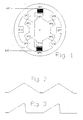
- Fig. 1 shows the representation of a conventional switched Reluctance motor with 8 stator and 6 rotor poles.
- Fig. 2 indicates the basic time course of the opposing effective pole faces conventional engines.
- Fig. 3 shows the asymmetrical course of time opposite effective pole faces for the present Invention.
- Fig. 4 illustrates for the embodiment 1 Control of the magnetic flux between the stator poles An, Bn through the at different speeds revolving rotor poles Cn and D. It is the developed form 5.
- Fig. 5 also shows for embodiment 1 Control of the magnetic flux between the stator poles An, Bn through the at different speeds revolving rotor poles Cn and D. It is the correct angle Representation of FIG. 4.
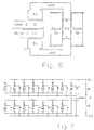
- Fig. 6 shows the basic arrangement of permanent magnet and Coil as well as the entire magnetic circuit between the Stator poles An and Bn.
- FIG 7 shows the interconnection for embodiment 1 the excitation coils S1 to S15 and the arrangement of the electronic switches T1 to T15 for correct phase Advance counter-excitation.
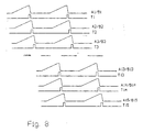
- FIG 8 is a phase diagram for embodiment 1 of FIG the effective pole face courses and the closing times the electronic phase switch for the 15 pole pairs and Coils can be seen.
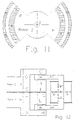
- Fig. 9 shows a section of the embodiment 2 with the circumferential 16 magnetic poles and the fixed coils 1 and 2 and the inner rotor with pole pieces 4, 5, 6 and 7.
- FIG. 10 is also a sectional drawing of the embodiment 2.
- the cutting plane is 90 degrees compared to FIG. 7 turned. It will be the bearing of the two rotors that They fix the gear coupling between the coils two rotors shown schematically.
- Fig. 11 is the axial view of the inner rotor in Embodiment 2.
- the rotor poles are hatched drawn.
- FIG. 12 shows a sectional drawing for the exemplary embodiment 3. It is especially the soft magnetic ones Elements for guiding the magnetic flux in rotor 1 and Rotor 2 shown.
- FIG 13 is the phase diagram for embodiment 3 of FIG the effective pole face courses and the closing times the electronic phase switch for the 15 pole pairs and Coils can be seen.
- a switched reluctance motor e.g. from a soft magnetic rotor with 6 poles (RP1 ... RP6) and a stator with 8 poles (SP1 ... SP8).
- the stator poles each have one Excitation coil, which become coils of opposite poles electrically interconnected and form the north-south pole pair for one phase.
- Fig. 1 are only for clarity the coils of SP1 and SP5 indicated.
- suitable Electronic switches will correct the pole pairs Sequence and coordinated period of time are supplied with current and magnetically excited. Through continuous, correct angles Switching the phase currents becomes the desired torque reached.
- the present invention is based on the approach for which magnetic excitation of the poles not electromagnets, but Use permanent magnets and other suitable ones Means a switched reluctance motor with improved To maintain efficiency.
- the increase and decrease of the magnetic flux symmetrical when the rotor pole is at Stator pole moves past at constant angular velocity.
- the effective magnetic flux is a first approximation proportional to the opposing areas of the rotor and stator coils.
- the typical temporal Course of these areas for a conventional engine is shown schematically in Fig. 2 for illustration.
- the conventional reluctance motor is powered while the rotor and stator poles move towards each other.
- the switched reluctance motor shown here with Excitation by permanent magnets must be with the excitation coils Electricity is applied while the poles are apart remove so the resulting field in this Movement phase becomes zero.
- Power for the counter-excitation of the current duration proportional is the one to be used Power for the counter-excitation of the current duration proportional.
- Exemplary embodiment 1 is based on FIGS. 4 to 6 explained in more detail.
- Fig. 4 and Fig. 5 are content identical.
- FIG. 4 is the linear representation of FIG. 5.
- A1 to A15 and B1 to B15 each represent stator pole pairs that are even with an angular distance of 24 degrees are distributed over the circumference of the stator. You are constructively preferably on two different spatial levels.
- the torque can be taken from the rotor 1.
- C1 to C16 are the soft magnetic rotor poles of the first Rotors with an angular distance of 22.5 degrees are evenly distributed over the entire rotor circumference.
- the second rotor D has a magnetically conductive one Area over an angle of 168 degrees (7x24).
- the width the pole itself is 11 degrees in this example.
- Other combinations of poles are of course also possible if the angular relationships to each other be coordinated.
- the second rotor rotates in the same phase Direction exactly at 16 times the speed of rotor 1 (counter clockwise in the example shown). This can be done with little effort e.g. by a reach the corresponding gear coupling.
- the switches T1 to T15 are preferably designed as electronic switches.
- 9 to 11 show embodiment 2: Around a stationary coil, which is divided into two halves for design reasons only, 2 rotors orbits at different speeds, the axes of rotation of which are offset by 90 degrees.
- the first rotor is made of highly permeable Material and has 16 magnetic poles (Neodymium-iron-boron or samarium-cobalt alloy or equivalent) on, north and south poles in alternating Sequence.
- the second rotor (F) is inside the first in the bearings (2) and (3) rotatably about the axis (1).
- This Rotor axis and the other components of the inner rotor are made of soft magnetic material with the lowest possible To produce eddy current losses.
- the inner rotor (F) has pole shoe pairs 4 to 7, their Surfaces ideally like the pole surfaces of the first Rotors in the form of concentric spherical shell sections are formed so that the resulting air gaps between the pole pieces.
- Fig. 11 shows the top view of this inner rotor (F).
- the pole pieces are hatched.
- the poles of the inner rotor cover an angular range of 84.25 degrees.
- the magnetic flux course is with reference to Fig. 9 in the angular position shown slightly to be represented:
- the south pole (S) of the first rotor, pole piece (4), rotor axis (1), pole piece (5) and north pole (N) of the first rotor close the magnetic circuit.
- the coil form for coil 1 and coil 2 have none mechanical contact to the second rotor (F). You can through suitable fastenings (see Fig. 10) in their Target position are maintained, contacting via wear-prone slip rings are no longer necessary.
- the two coils are fixed via the holding device (14) connected to the support frame (13) and are thereby in held their target position.
- the support structure (11) for the outer rotor (8) is by means of the bearings (10) rotatable around the two hollow shafts (12) stored. The torque can't over a here the drawn ring gear removed from the outer rotor become.
- the two rotors are phase locked with the right ones Move speeds.
- the inner rotor must be 8 times the angular velocity of the outer rotor rotate.
- the average torque that can be achieved can therefore be reduced by low additional constructive measures significantly increased become.
Landscapes
- Engineering & Computer Science (AREA)
- Power Engineering (AREA)
- Synchronous Machinery (AREA)
- Control Of Electric Motors In General (AREA)
Abstract
Description
Die Erfindung betrifft einen geschalteten Reluktanzmotor.The invention relates to a switched reluctance motor.
Unter einem geschalteten Reluktanzmotor (engl: Switched Reluctance Motor, SR) versteht man ein Antriebsprinzip, bei dem die Anziehungskraft eines Magneten gegen Eisen zur Drehmomenterzeugung verwendet wird. Anders ausgedrückt: Es handelt sich um eine Anordnung, bei der das System bestrebt ist, den magnetischen Kreis in den Zustand des geringsten magnetischen Widerstandes (Reluktanz) zu bringen.Under a switched reluctance motor Reluctance Motor, SR) means a drive principle, at which the attraction of a magnet against iron Torque generation is used. In other words, it is an arrangement in which the system strives is the magnetic circuit in the state of the least bring magnetic resistance (reluctance).
Eine übliche Anordnung, die weiter unten ausführlicher beschrieben wird, besteht z.B. aus einem weichmagnetischen Rotor mit einer bestimmten Anzahl von Polen und einem Stator mit mindestens ebensovielen Polen. Die Statorpole besitzen jeweils eine Erregerspule, die Spulen der gegenüberliegenden Pole werden elektrisch zusammengeschaltet und bilden das Nord-/Südpolpaar für eine Bewegungsphase.A common arrangement, which is detailed below there is e.g. from a soft magnetic Rotor with a certain number of poles and a stator with at least as many Poles. Own the stator poles one excitation coil each, the coils of the opposite Poles are electrically interconnected and form that North / south pole pair for a movement phase.
Durch geeignete elektronische Schalter werden die Polpaare in richtiger Reihenfolge und abgestimmter Zeitdauer mit Strom beaufschlagt und magnetisch erregt. Durch fortlaufendes, winkelrichtiges Weiterschalten der Phasenströme wird das gewünschte Drehmoment erreicht.Appropriate electronic switches are used to switch the pole pairs in correct order and coordinated period of time with electricity acted upon and magnetically excited. By continuous, it will switch the phase currents at the correct angle desired torque reached.
Aus PATENT ABSTRACTS OF JAPAN vol. 010, no, 319 (E-450) 30. Oktober 1986 & JP-A-61 128 761 (ISHIKAWAJIMA HARIMA HEAVY IND CO LTD) 16. Juni 1986 ist ein geschalteter Reluktanzmotor mit einem Permanentmagneten und einem Elektromagneten bekannt. In vorbestimmten Zeitintervallen wird das Magnetfeld des Permanentmagneten durch ein vom Elektromagneten erzeugtes Gegenmagnetfeld kompensiert. From PATENT ABSTRACTS OF JAPAN vol. 010, no, 319 (E-450) October 30, 1986 & JP-A-61 128 761 (ISHIKAWAJIMA HARIMA HEAVY IND CO LTD) June 16, 1986 is a switched reluctance motor with a permanent magnet and an electromagnet known. At predetermined time intervals is the magnetic field of the permanent magnet by a Counter magnetic field generated by the electromagnet is compensated.
In US-A-4 882 509 ist ein geschalteter Reluktanzmotor mit einem Stator, der vorzugsweise aus Elektromagneten aufgebaut ist, und einem Rotor beschrieben, der vorzugsweise aus Permanentmagneten aufgebaut ist. Zur Erzeugung eines Drehmomentes werden die Elektromagnete während vorbestimmter Zeitintervalle bestromt. Zwischen dem Rotor und dem Stator rotiert ein Schild, der aus supraleitendem Material hergestellt ist und einen Bogen von etwas mehr als 90° bildet, mit der gleichen Geschwindigkeit jedoch in entgegengesetzter Richtung wie der Rotor. Der rotierende Schild dient dazu, die magnetische Kopplung zwischen dem Stator und dem Rotor zu unterbrechen.In US-A-4 882 509 is a switched reluctance motor with a stator, which is preferably made of electromagnets is constructed, and described a rotor, which is preferably is made up of permanent magnets. For generation the electromagnets become a torque energized during predetermined time intervals. Between the rotor and the stator rotates a shield that is out superconducting material is made and an arc of just over 90 ° at the same speed however in the opposite direction as the rotor. The rotating shield serves the magnetic one Coupling between the stator and the rotor to interrupt.
Aus US-A-5 117 144 ist ein geschalteter Reluktanzmotor bekannt, der aus einem Stator, aus dem Magnetpolpaare - ein ferromagnetischer und ein permanentmagnetischer Pol - angeordnet sind, sowie aus einem Rotor aufgebaut ist. An jedem Pol des Rotors ist eine Nase vorgesehen. Infolge dieser Nasen an den Polen des Rotors ist es möglich, den Reluktanzmotor mittels nur eines einzigen elektronischen Schalters, beispielsweise eines Schalttransistors, zu steuern.From US-A-5 117 144 is a switched reluctance motor known from a stator, from the magnetic pole pairs - a ferromagnetic and a permanent magnetic Pol - are arranged, as well as built up from a rotor is. A nose is provided on each pole of the rotor. As a result of these lugs on the poles of the rotor it is possible to use a single reluctance motor electronic switch, for example a switching transistor, to control.
Der Erfindung liegt die Aufgabe zugrunde, eine Variante eines geschalteten Reluktanzmotors mit besserem Wirkungsgrad anzugeben.The invention has for its object a variant of to indicate switched reluctance motor with better efficiency.
Ein solcher Reluktanzmotor ist gekennzeichnet
- durch Permanentmagnete zur Erzeugung von Drehmomenten,
- durch schaltbare elektromagnetische Spulen, die dafür vorgesehen sind, das Magnetfeld mindestens eines Permanentmagneten in vorbestimmten Zeitintervallen zu kompensieren,
- sowie durch konstruktive Mittel, die den Reluktanzverlauf als Funktion des Rotorwinkels unsymmetrisch gestalten.
- by permanent magnets for the generation of torques,
- by switchable electromagnetic coils which are intended to compensate for the magnetic field of at least one permanent magnet at predetermined time intervals,
- as well as constructive means that make the reluctance curve asymmetrical as a function of the rotor angle.
Bei einer Erregung durch Permanentmagnete wird erfindungsgemäß ein positives mittleres Drehmoment dadurch erhalten, daß die Wirkung der Permanentmagnete ausgeschaltet oder zumindest ausreichend stark reduziert wird, wenn sich der Rotorpol vom Statorpol entfernt. When excited by permanent magnets, the invention obtain a positive mean torque by: the effect of the permanent magnets switched off or at least is reduced sufficiently if the rotor pole moves away from the Stator pole removed.
Dies ist bei heutigen modernen Magnetwerkstoffen (Neodymium-Eisen-Bor- bzw. Samarium-Cobalt-Legierungen) durch eine gleich starke Gegenerregung über eine elektromagnetische Spule während der entsprechenden Bewegungsphase erreichbar. Der resultierende magnetische Fluß kann auf diese Weise praktisch zu Null gemacht werden, eine irreversible Entmagnetisierung erfolgt bei den genannten Magnetwerkstoffen nicht.This is the case with today's modern magnetic materials (Neodymium-iron-boron or samarium-cobalt alloys) an equally strong counterexcitation via an electromagnetic The coil can be reached during the corresponding movement phase. The resulting magnetic flux can in this way be made practically zero, an irreversible Demagnetization takes place with the magnetic materials mentioned Not.
Da die aufzuwendende Leistung für die Gegenerregung zur Bestromungsdauer proportional ist, sind zur Verkürzung dieser Dauer und damit zur Erhöhung des Wirkungsgrades Mittel vorgesehen, die Reluktanz zwischen Rotor- und Statorpolen des Motors in vorbestimmten Zeitintervallen möglichst groß zu machen.Since the power to be used for counter-excitation Current supply time is proportional to shorten this Duration and thus to increase the efficiency means provided the reluctance between the rotor and stator poles of the Motor as large as possible in predetermined time intervals do.
Eine Erhöhung der Reluktanz in vorbestimmten Zeitintervallen zwischen Rotor- und Statorpolen des Motors bedeutet eine Verminderung der Kräfte zwischen diesen Polen in den vorbestimmten Zeitintervallen. Werden die Zeitintervalle großer Reluktanz ebenfalls in die Phase gelegt, in der ein Rotorpol sich vom Statorpol entfernt, so kann die Kompensation des Magnetfeldes während der Zeitintervalle großer Reluktanz gegebenenfalls ganz unterbleiben, d.h. die Zeitintervalle, in denen das Magnetfeld kompensiert wird, können verkürzt werden.An increase in reluctance at predetermined time intervals between the rotor and stator poles of the motor means one Reduction in forces between these poles in the predetermined time intervals. Become the time intervals great reluctance also placed in the phase in which a Rotor pole away from the stator pole, so the Compensation of the magnetic field during the time intervals large reluctance may not occur at all, i.e. the Time intervals in which the magnetic field is compensated can be shortened.
Anhand der Figuren und anhand von Ausführungsbeispielen soll die Erfindung nun näher erläutert werden.Based on the figures and using exemplary embodiments the invention will now be explained in more detail.
Die Figuren haben folgende Bedeutung:The figures have the following meaning:
Fig. 1 zeigt die Darstellung eines üblichen geschalteten Reluktanzmotors mit 8 Stator- und 6 Läuferpolen.Fig. 1 shows the representation of a conventional switched Reluctance motor with 8 stator and 6 rotor poles.
Fig. 2 kennzeichnet den prinzipiellen zeitlichen Verlauf der sich gegenüberstehenden wirksamen Polflächen bei konventionellen Motoren.Fig. 2 indicates the basic time course of the opposing effective pole faces conventional engines.
Fig. 3 stellt den unsymmetrischen zeitlichen Verlauf der sich gegenüberstehenden wirksamen Polflächen für die vorliegende Erfindung dar.Fig. 3 shows the asymmetrical course of time opposite effective pole faces for the present Invention.
Fig. 4 veranschaulicht für das Ausführungsbeispiel 1 die
Steuerung des magnetischen Flusses zwischen den Statorpolen
An, Bn durch die mit unterschiedlicher Geschwindigkeit
umlaufenden Rotorpole Cn und D. Sie ist die abgewickelte Form
der Fig. 5.Fig. 4 illustrates for the
Fig. 5 zeigt ebenfalls für das Ausführungsbeispiel 1 die
Steuerung des magnetischen Flusses zwischen den Statorpolen
An, Bn durch die mit unterschiedlicher Geschwindigkeit
umlaufenden Rotorpole Cn und D. Sie ist die winkelrichtige
Darstellung der Fig. 4. Fig. 5 also shows for
Fig. 6 zeigt die prinzipielle Anordung von Dauermagnet und Spule sowie den gesamten magnetischen Kreis zwischen den Statorpolen An und Bn.Fig. 6 shows the basic arrangement of permanent magnet and Coil as well as the entire magnetic circuit between the Stator poles An and Bn.
Fig. 7 zeigt für Ausführungsbeispiel 1 die Zusammenschaltung
der Erregerspulen S1 bis S15 sowie die Anordnung der
elektronischen Schalter T1 bis T15 zur phasenrichtigen
Weiterschaltung der Gegenerregung.7 shows the interconnection for
Fig. 8 ist ein Phasendiagramm für Ausführungsbeispiel 1, aus
dem die wirksamen Polflächenverläufe sowie die Schließzeiten
der elektronischen Phasenschalter für die 15 Polpaare und
Spulen ersichtlich werden.8 is a phase diagram for
Fig. 9 zeigt einen Schnitt des Ausführungsbeispiels 2 mit den
umlaufenden 16 Magnetpolen und den feststehenden Spulen 1 und
2 sowie dem inneren Rotor mit den Polschuhen 4, 5, 6 und 7.Fig. 9 shows a section of the
Fig. 10 ist ebenfalls eine Schnittzeichnung des Ausführungsbeispiels
2. Die Schnittebene ist gegenüber Fig. 7 um 90 Grad
gedreht. Es wird die Lagerung der beiden Rotoren, die
Spulenbefestigung sie die Getriebekopplung zwischen den
beiden Rotoren schematisch dargestellt.10 is also a sectional drawing of the
Fig. 11 ist die achsiale Ansicht des inneren Rotors im
Ausführungsbeispiel 2. Die Rotorpole sind schraffiert
gezeichnet.Fig. 11 is the axial view of the inner rotor in
Fig. 12 zeigt eine Schnittzeichnung für das Ausführungsbeispiel
3. Es sind insbesondere die weichmagnetischen
Elemente zur Leitung des magnetischen Flusses in Rotor 1 und
Rotor 2 dargestellt.12 shows a sectional drawing for the
Fig. 13 ist das Phasendiagramm für Ausführungsbeispiel 3, aus
dem die wirksamen Polflächenverläufe sowie die Schließzeiten
der elektronischen Phasenschalter für die 15 Polpaare und
Spulen ersichtlich werden. 13 is the phase diagram for
Die übliche Anordnung eines geschalteten Reluktanzmotors (siehe Fig.1) besteht z.B. aus einem weichmagnetischen Rotor mit 6 Polen (RP1...RP6) und einem Stator mit 8 Polen (SP1...SP8). Die Statorpole besitzen jeweils eine Erregerspule, die Spulen der gegenüberliegenden Pole werden elektrisch zusammengeschaltet und bilden das Nord-Südpolpaar für eine Phase. In Fig. 1 sind der Übersichtlichkeit wegen nur die Spulen von SP1 und SP5 angedeutet. Durch geeignete elektronische Schalter werden die Polpaare in richtiger Reihenfolge und abgestimmter Zeitdauer mit Strom beaufschlagt und magnetisch erregt. Durch fortlaufendes, winkelrichtiges Weiterschalten der Phasenströme wird das gewünschte Drehmoment erreicht.The usual arrangement of a switched reluctance motor (see Fig. 1) e.g. from a soft magnetic rotor with 6 poles (RP1 ... RP6) and a stator with 8 poles (SP1 ... SP8). The stator poles each have one Excitation coil, which become coils of opposite poles electrically interconnected and form the north-south pole pair for one phase. In Fig. 1 are only for clarity the coils of SP1 and SP5 indicated. By suitable Electronic switches will correct the pole pairs Sequence and coordinated period of time are supplied with current and magnetically excited. Through continuous, correct angles Switching the phase currents becomes the desired torque reached.
Die vorliegende Erfindung beruht auf dem Ansatz, für die magnetische Erregung der Pole nicht Elektromagneten, sondern Permanentmagneten zu verwenden und durch weitere geeignete Mittel einen geschalteten Reluktanzmotor mit verbessertem Wirkungsgrad zu erhalten.The present invention is based on the approach for which magnetic excitation of the poles not electromagnets, but Use permanent magnets and other suitable ones Means a switched reluctance motor with improved To maintain efficiency.
Üblicherweise verläuft bei Motoren die Zu- und Abnahme des magnetischen Flusses symmetrisch, wenn sich der Rotorpol am Statorpol mit konstanter Winkelgeschwindigkeit vorbeibewegt. Der wirksame magnetische Fluß ist dabei in erster Näherung proportional zu den sich gegenüberstehenden Flächenanteilen des Rotor- und des Statorspoles. Der typische zeitliche Verlauf dieser Flächenanteile für einen herkömmlichen Motor ist zur Veranschaulichung in Fig. 2 schematisch dargestellt.The increase and decrease of the magnetic flux symmetrical when the rotor pole is at Stator pole moves past at constant angular velocity. The effective magnetic flux is a first approximation proportional to the opposing areas of the rotor and stator coils. The typical temporal Course of these areas for a conventional engine is shown schematically in Fig. 2 for illustration.
Es ist unmittelbar ersichtlich, daß bei einer Erregung durch Permanentmagnete zusätzliche Maßnahmen notwendig sind, damit ein positives mittleres Drehmoment erhalten wird: Wenn sich der Rotorpol von dem Statorpol entfernt, muß die Wirkung des Permanentmagneten ausgeschaltet oder zumindest ausreichend stark reduziert werden. Dies ist bei heutigen modernen Magnetwerkstoffen (Neodymium-Eisen-Bor- bzw. Samarium-Cobalt-Legierungen) durch eine gleich starke Gegenerregung über eine Statorspule während der entsprechenden Bewegungsphase erreichbar. Der resultierende magnetische Fluß kann auf diese Weise vorübergehend praktisch auf Null gebracht werden, eine irreversible Entmagnetisierung erfolgt bei den o.a. Magnetwerkstoffen nicht.It is immediately apparent that when excited by Permanent magnets additional measures are necessary so a positive mean torque is obtained: if the rotor pole away from the stator pole, the effect of Permanent magnets switched off or at least sufficient be greatly reduced. This is modern in today's Magnetic materials (neodymium-iron-boron or samarium-cobalt alloys) by an equally strong counter-excitation over a Stator coil during the corresponding movement phase reachable. The resulting magnetic flux can affect this Way to be practically zeroed temporarily, one irreversible demagnetization occurs with the above Magnetic materials are not.
Der herkömmliche Reluktanzmotor wird mit Strom beaufschlagt, während sich die Rotor- und Statorpole aufeinander zu bewegen. Beim hier dargestellten geschalteten Reluktanzmotor mit Erregung durch Permanentmagneten müssen die Erregerspulen mit Strom beaufschlagt werden, während sich die Pole voneinander entfernen, damit das resultierende Feld in dieser Bewegungsphase zu Null wird. Dabei ist die aufzuwendende Leistung für die Gegenerregung der Bestromungsdauer proportional. The conventional reluctance motor is powered while the rotor and stator poles move towards each other. With the switched reluctance motor shown here with Excitation by permanent magnets must be with the excitation coils Electricity is applied while the poles are apart remove so the resulting field in this Movement phase becomes zero. Here is the one to be used Power for the counter-excitation of the current duration proportional.
In vorliegender Erfindung wird durch geeignete Maßnahmen erreicht, daß die den magnetischen Fluß bestimmenden Rotor- bzw. Stator-Flächenanteile unsymmetrisch zu- bzw. abnehmen: Der Anstieg des magnetischen Flusses erfolgt in der üblichen Zeit (während der Rotorpol zum Stator-Polschuh wandert), das Verkleinern der wirksamen Polflächen (während der Rotorpol sich vom Stator-Polschuh entfernt) erfolgt jedoch durch geeignete Maßnahmen in sehr viel kürzerer Zeit.In the present invention by suitable measures achieves that the rotor or Stator area proportions increase or decrease asymmetrically: The increase in the magnetic flux takes place in the usual time (during the rotor pole to the stator pole shoe migrates), reducing the effective pole faces (while the rotor pole moves away from the stator pole shoe) however, through appropriate measures in a much shorter time Time.
Dieser Zusammenhang ist in Fig. 3 schematisch dargestellt. Nach den o.a. Ausführungen reduziert sich damit die aufzubringende Leistung für die Gegenerregung umso mehr, je günstiger das Verhältnis dieser beiden Zeiten wird.This relationship is shown schematically in FIG. 3. According to the above This reduces the number of executions performance to be provided for the counterexcitation the more, ever the ratio of these two times becomes more favorable.
Theoretisch ließe sich dies durch Variation der Rotor-Winkelgeschwindigkeit in den jeweiligen Bewegungsphasen erreichen. Praktisch scheidet ein solcher Weg natürlich aus, weil solche abrupten Änderungen aufgrund des mechanischen Rotor-Trägheitsmoments nicht möglich und im Sinne einer möglichst guten Laufruhe auch nicht erstrebenswert sind.Theoretically, this could be done by varying the Rotor angular velocity in the respective movement phases to reach. In practice, of course, such a path is different out because such abrupt changes due to the mechanical rotor moment of inertia not possible and in Neither in terms of smooth running are desirable.
Ein weiterer prinzipiell möglicher Lösungsansatz besteht darin, jeden einzelnen Stator- oder Rotorpol mit geeigneten Vorrichtungen zu versehen, die im Augenblick der Gegenerregung den magnetischen Widerstand in sehr kurzer Zeit möglichst groß werden lassen. Dies führt jedoch zu erheblichem konstruktiven Aufwand und zu zusätzlichem Energieverbrauch zur Steuerung dieser Mittel.Another possible approach exists in principle in making each individual stator or rotor pole suitable To provide devices at the moment of counterexcitation the magnetic resistance in a very short time let it grow as big as possible. However, this leads to considerable constructive effort and additional energy consumption to control these funds.
Nachfolgend werden 3 unterschiedliche Realisierungs-Varianten für die angesprochene Aufgabe beschrieben. Es geht dabei nur um die prinzipiellen Lösungsansätze. Modifikationen dieser Varianten wie Änderung der Polzahlen oder der mechanischen Konstruktionsmerkmale zur Fertigungsoptimierung sind natürlich möglich und ggfs. sinnvoll. Die üblichen Konstruktionsregeln und Materialanforderungen zur Erreichung geringer Wirbelstromverluste, Vermeidung der magnetischen Sättigung, Minimierung der Luftspalte usw. sollen an dieser Stelle nicht angesprochen werden.Below are 3 different implementation options described for the task in question. It is only about the basic solutions. Modifications of these variants such as changing the number of poles or the mechanical design features for manufacturing optimization are of course possible and useful if necessary. The usual design rules and material requirements for Achieve low eddy current losses, avoid the magnetic saturation, minimization of air gaps, etc. should not be addressed here.
Das Ausführungs-Beispiel 1 sei anhand der Figuren 4 bis 6
näher erläutert. Fig. 4 und Fig. 5 sind inhaltlich
identisch. Fig. 4 ist die lineare Darstellung der Fig. 5.
A1 bis A15 und B1 bis B15 stellen jeweils Stator-Polpaare
dar, die mit einem Winkelabstand von 24 Grad gleichmäßig
über den Statorumfang verteilt sind. Sie befinden sich
konstruktiv vorzugsweise auf zwei unterschiedlichen
räumlichen Ebenen.
Das Drehmoment kann am Rotor 1 entnommen werden. The torque can be taken from the
C1 bis C16 sind die weichmagnetischen Rotorpole des ersten Rotors, die mit einem Winkelabstand von 22,5 Grad gleichmäßig über den gesamten Rotorumfang verteilt sind. Der zweite Rotor D besitzt einen magnetisch leitenden Bereich über einen Winkel von 168 Grad (7x24). Die Breite der Pole selbst beträgt bei diesem Beispiel 11 Grad. Andere Polzahl-Kombinationen sind natürlich ebenfalls möglich, wenn die Winkel-Verhältnisse aufeinander abgestimmt werden.C1 to C16 are the soft magnetic rotor poles of the first Rotors with an angular distance of 22.5 degrees are evenly distributed over the entire rotor circumference. The second rotor D has a magnetically conductive one Area over an angle of 168 degrees (7x24). The width the pole itself is 11 degrees in this example. Other combinations of poles are of course also possible if the angular relationships to each other be coordinated.
In den Figuren 4 und 5 sind aus Gründen der Übersichtlichkeit die zugehörigen Permanentmagnete, die Spulen für die Gegenerregung sowie die Spulen-Joche nicht eingezeichnet. Aus der Prinzip-Skizze Fig. 6 ist zu ersehen, wie der magnetische Kreis zwischen den Statorpolen An/Bn über ein magnetisch leitendes Joch und den Permanentmagneten PM geschlossen wird. Die Spule für die Gegenerregung kann den Permanentmagneten umschließen. Auf die genaue Dimensionierung oder die Auswahl geeigneter Materialien muß an dieser Stelle nicht eingegangen werden. Konstruktive Varianten sind möglich.4 and 5 are for reasons of clarity the associated permanent magnets, the coils for the counterexcitation and the coil yokes are not drawn. From the principle sketch Fig. 6 is too see how the magnetic circuit between the stator poles An / Bn via a magnetically conductive yoke and the Permanent magnet PM is closed. The coil for the Counter-excitation can enclose the permanent magnet. On the exact dimensioning or the selection of suitable ones Materials do not have to be received here. Constructional variants are possible.
Um den o.a. unsymmetrischen Reluktanzverlauf zu erhalten, dreht sich der zweite Rotor phasenstarr in gleicher Richtung genau mit der 16-fachen Geschwindigkeit von Rotor 1 (im dargestellten Beispiel gegen den Uhrzeigersinn). Dies läßt sich mit geringem Aufwand z.B. durch eine entsprechende Zahnrad-Kupplung erreichen.To the above to obtain an asymmetrical reluctance curve the second rotor rotates in the same phase Direction exactly at 16 times the speed of rotor 1 (counter clockwise in the example shown). This can be done with little effort e.g. by a reach the corresponding gear coupling.
Der wirksame Polflächenverlauf an den Polen An/Bn
entspricht auf diese Weise qualitativ dem in Bild 3
dargestellten Verlauf. In der gezeichneten Rotorposition
der Figur 5 muß die A1/B1 zugeordnete Erreger-Spule
kurzzeitig mit Strom beaufschlagt werden, damit der Pol C1
des Rotors 1 und das Rotorsegment D des Rotors 2 sich
vom Stator-Polpaar A1/B1 lösen können. Die notwendige
Bestromungsdauer wird bestimmt durch die Zeit, während der
sich das Rotorsegment D im Anziehungsbereich des Statorpols
A1 und des Rotorpols C1 befindet. Das Zeitverhältnis
zwischen Stromfluß und stromlosem Zustand der
Erreger-Spulen ist im vorliegenden Beispiel besser als 1:21
(16,75 Grad/360 Grad).The effective course of the pole faces at the poles An / Bn
This corresponds qualitatively to that in Figure 3
shown course. In the drawn
Entsprechend dem Reluktanz-Prinzip (Minimierung des resultierenden magnetischen Widerstandes) wird in der gezeigten Winkelstellung der Figur 5 durch die Rotorpole C2...C8 ein positives Drehmoment erzielt. Das durch die Rotorpole C10...C16 erzeugte Gegendrehmoment ist wegen des sehr großen Luftspaltes dieser Rotorpole gegen die Statorpole B9...B15 sehr viel kleiner. Von besonderem Vorteil ist es, daß in den Erregerspulen, die jeweils über das Rotorsegment D und die Rotorpole Cn einen starken Anstieg des magnetischen Flusses erfahren (in der gezeichneten Rotorposition sind das die den Statorpolen A2...A8 zugeordneten Spulen) eine elektrische Spannung induziert wird. According to the reluctance principle (minimization of the resulting magnetic resistance) is in the shown angular position of Figure 5 by the rotor poles C2 ... C8 achieves a positive torque. That through the Rotor poles C10 ... C16 generated counter torque is due to the very large air gap of these rotor poles against the Stator poles B9 ... B15 much smaller. It is particularly advantageous that in the excitation coils, which each via the rotor segment D and the rotor poles Cn experience a sharp increase in magnetic flux (in In the drawn rotor position, these are the stator poles A2 ... A8 associated coils) an electrical voltage is induced.
Es kann also aus diesen Spulen ggfs. ein Teil der elektrischen Leistung zurückgewonnen werden, die zur Gegenerregung des permanentmagnetischen Feldes aufgebracht werden muß. Das resultierende mechanische Drehmoment reduziert sich in diesem Fall um den entsprechenden Betrag.A part of the electrical power to be recovered, which is used for Counterexcitation of the permanent magnetic field applied must become. The resulting mechanical torque is reduced in this case by the corresponding amount.
In Fig. 8 ist der resultierende zeitliche Polflächenverlauf für das Ausführungs-Beispiel 1 sowie die Phasenbeziehung der Polpaare zueinander dargestellt.8 shows the resulting temporal pole face course for execution example 1 and the phase relationship of the pole pairs to each other.
In Fig. 7 ist eine mögliche Zusammenschaltung der Erregerspulen S1 bis S15 sowie der Anschluß an das äußere Klemmenpaar KL1 und K12 dargestellt. Die Dioden entkoppeln das jeweilige Spulenpaar in der Phase der Gegenerregung (zugehörige Schalter geschlossen) von der jeweils gegenpoligen Anschlußklemme. Bei Öffnen der Schalter dienen sie gleichzeitig der Rückgewinnung der in den Spuleninduktivitäten gespeicherten Energie. Die Schalter T1 bis T15 werden bevorzugt als elektronische Schalter ausgeführt.7 shows a possible interconnection of the excitation coils S1 to S15 and the connection to the outside Terminal pair KL1 and K12 shown. Decouple the diodes the respective coil pair in the phase of counter-excitation (associated switch closed) from the opposite pole Connector. They serve when the switches are opened at the same time the recovery of the inductors in the coil stored energy. The switches T1 to T15 are preferably designed as electronic switches.
Die Einschalt-Zeitpunkte der Schalter sowie die Phasenlage zueinander gehen ebenfalls aus Fig. 7 hervor.The switch on times and the phase position to each other are also apparent from Fig. 7.
Weitere Schaltungseinheiten und Schaltungsanordnungen zur Positionsmessung und Drehzahlregelung werden hier nicht angesprochen, da sie mit konventionellen Lösungsansätzen zu erledigen sind.Further circuit units and circuit arrangements for Position measurement and speed control are not here addressed, since they use conventional solutions are done.
In den Fig. 9 bis 11 wird das Ausführungs-Beispiel 2
dargestellt:
Um eine stationäre Spule, die lediglich aus konstruktiven
Gründen in zwei Hälften aufgeteilt wird, kreisen mit
unterschiedlichen Geschwindigkeiten 2 Rotoren, deren
Rotationsachsen um 90 Grad gegeneinander versetzt sind.9 to 11 show embodiment 2:
Around a stationary coil, which is divided into two halves for design reasons only, 2 rotors orbits at different speeds, the axes of rotation of which are offset by 90 degrees.
In Fig. 9 befindet sich die Achse des Rotors 1 senkrecht
zur Zeichenebene. Der erste Rotor besteht aus hochpermeablem
Material und weist 16 magnetische Pole
(Neodymium-Eisen-Bor- bzw. Samarium-Cobalt-Legierung oder
gleichwertig) auf, Nord- und Südpole in alternierender
Reihenfolge.In Fig. 9, the axis of the
Der zweite Rotor (F) ist innerhalb des ersten in den Lagern (2) und (3) um die Achse (1) drehbar gelagert. Diese Rotorachse und die anderen Bestandteile des inneren Rotors sind aus weichmagnetischem Material mit möglichst geringen Wirbelstromverlusten zu fertigen.The second rotor (F) is inside the first in the bearings (2) and (3) rotatably about the axis (1). This Rotor axis and the other components of the inner rotor are made of soft magnetic material with the lowest possible To produce eddy current losses.
Der innere Rotor (F) besitzt Polschuh-Paare 4 bis 7, deren Flächen idealerweise wie auch die Polflächen des ersten Rotors in Form konzentrischer Kugelschalen-Abschnitte ausgebildet sind, damit die resultierenden Luftspalte zwischen den Polschuhen minimal werden.The inner rotor (F) has pole shoe pairs 4 to 7, their Surfaces ideally like the pole surfaces of the first Rotors in the form of concentric spherical shell sections are formed so that the resulting air gaps between the pole pieces.
Fig. 11 zeigt die Draufsicht auf diesen inneren Rotor (F). Die Polschuhe sind schraffiert gezeichnet. Bei der gewählten Polzahl und quadratischen Flächen der Magnetpole überstreichen die Pole des inneren Rotors einen Winkelbereich von 84,25 Grad. Der magnetische Flußverlauf ist anhand der Fig. 9 in der gezeichneten Winkelposition leicht darzustellen: Der Südpol (S) des ersten Rotors, Polschuh (4), Rotorachse (1), Polschuh (5) und Nordpol (N) des ersten Rotors schließen den magnetischen Kreis.Fig. 11 shows the top view of this inner rotor (F). The pole pieces are hatched. In the selected number of poles and square areas of the magnetic poles the poles of the inner rotor cover an angular range of 84.25 degrees. The magnetic flux course is with reference to Fig. 9 in the angular position shown slightly to be represented: The south pole (S) of the first rotor, pole piece (4), rotor axis (1), pole piece (5) and north pole (N) of the first rotor close the magnetic circuit.
Für die untere Spulenhälfte und die Polpaare (6) bzw. (7) gilt Sinngemäßes.For the lower half of the coil and the pole pairs (6) or (7) the same applies accordingly.
Da der Fluß in den beiden Spulenhälften gegensinnig verläuft, muß dies beim elektrischen Anschluß der Spulen berücksichtigt werden, damit die Gegenerregung vorzeichenrichtig wirken kann.Since the flow in the two coil halves in opposite directions this must be done when the coils are connected electrically are taken into account so that the counter-excitation is correct can work.
Die Spulenköper für Spule 1 und Spule 2 haben keinen
mechanischen Kontakt zum zweiten Rotor (F). Sie können
durch geeignete Befestigungen (Siehe Fig. 10) in ihrer
Sollposition gehalten werden, eine Kontaktierung über
verschleißanfällige Schleifringe erübrigt sich damit.The coil form for
Fig. 10 zeigt einen weiteren Schnitt des Ausführungsbeispiels
2, an dem die mechanischen Konstruktionsmerkmale
ersichtlich werden. Hier liegen jetzt die Achsen beider
Rotoren innerhalb der Zeichenebene.10 shows a further section of the
Fest verbunden mit dem Stativ (9) (oder ggfs. einem äußeren Gehäuse) sind die kurzen Hohlwellen (12), durch die die Stromzuführung zu den beiden Spulenteilen erfolgen kann. Eine geeignete Trägerkonstruktion (13) zur Aufnahme der Lager (2) und (3) für den zweiten Rotor ist auf den inneren Seiten fest mit den beiden Hohlwellen verbunden.Firmly connected to the tripod (9) (or an external one if necessary Housing) are the short hollow shafts (12) through which the Power can be supplied to the two coil parts. A suitable support structure (13) for receiving the Bearing (2) and (3) for the second rotor is on the inner one Sides firmly connected to the two hollow shafts.
Die beiden Spulen sind über die Haltevorrichtung (14) fest mit dem Trägerrahmen (13) verbunden und werden dadurch in ihrer Sollposition gehalten.The two coils are fixed via the holding device (14) connected to the support frame (13) and are thereby in held their target position.
Die Trägerkonstruktion (11) für den äußeren Rotor (8) ist mittels der Lager (10) drehbar um die beiden Hohlwellen (12) gelagert. Das Drehmoment kann über einen hier nicht eingezeichneten Zahnkranz vom äußeren Rotor abgenommen werden.The support structure (11) for the outer rotor (8) is by means of the bearings (10) rotatable around the two hollow shafts (12) stored. The torque can't over a here the drawn ring gear removed from the outer rotor become.
Für das Funktionieren der Anordnung ist Voraussetzung, daß
sich die beiden Rotoren phasenstarr mit den richtigen
Geschwindigkeiten bewegen. Bei den gewählten Polzahlen in
diesem Ausführungsbeispiel 2 muß sich der innere Rotor mit
der 8-fachen Winkelgeschwindigkeit des äußeren Rotors
drehen. For the arrangement to work, it is a prerequisite that
the two rotors are phase locked with the right ones
Move speeds. With the selected number of poles in
In this
Das läßt sich mit geringem Aufwand durch eine feste Zahnrad-Kopplung zwischen den beiden Rotoren erreichen. In Fig. 10 ist dies durch die Zahnräder (16) und (17) sowie den mit der Trägerkonstruktion (11) verbundenen Zahnkranz (15) angedeutet.This can be done with little effort by a fixed Reach gear coupling between the two rotors. In Fig. 10 this is through the gears (16) and (17) as well as the one connected to the support structure (11) Sprocket (15) indicated.
In der beschriebenen Anordnung ergibt sich ein zeitlicher Verlauf der wirksamen Polflächen ähnlich Fig. 3. Im Gegensatz zu Ausführungs-Beispiel 1 ist jedoch die Flußrichtung entsprechend der alternierenden Magnetpole des ersten Rotors ebenfalls alternierend. Aus diesem Grund muß die Gegenerregung vorzeichenrichtig ebenfalls mit alternierendem Vorzeichen erfolgen.In the arrangement described there is a temporal Course of the effective pole faces similar to Fig. 3. In Contrary to embodiment example 1, however Flow direction corresponding to the alternating magnetic poles of the first rotor also alternating. For this reason the counter excitation also with the correct sign alternating sign.
Vorteilhaft gegenüber dem Ausführungsbeispiel 1 ist, daß im
magnetischen Kreis nur 2 statt 3 Luftwege zu überwinden
sind, was bei vorgegebenen Magneten zu einer größeren
erreichbaren Flußdichte führt.An advantage over
baut auf dem 1. Beispiel auf. Die ungünstigen Zeitbereiche ohne magnetische Flußänderung des Beispiels 1 werden durch eine zweite, winkelversetzte Rotoranordnung vermieden, die zu dem in Fig. 13 dargestellten Polflächen-Verlauf führt. Die Funktion der zusätzlichen winkelversetzten Rotoranordnung läßt sich mit geringem Aufwand ebenfalls mit nur zwei Rotoren erreichen, die über die zugeordneten Winkelbereiche mit geeigneten Fluß-Leitstücken versehen sind. Dies ist in Fig. 12 angedeutet: Die Leitstücke (K) und (L) realisieren genau die Rotorpole des ersten Ausführungsbeispiels. Die Leitstücke (G) und (H) realisieren den dazu um 180 Grad versetzten Polflächenverlauf. Da sich die magnetisch leitenden Bereiche des schnell laufenden 2. Rotors über nur 168 Grad erstrecken, kommt es nicht zu Überschneidungen zwischen den Flußwegen (G,H) und (K,L).builds on the first example. The unfavorable time periods without magnetic flux change of Example 1 by avoided a second, angularly offset rotor arrangement, the leads to the pole face curve shown in FIG. 13. The function of the additional angularly offset rotor arrangement can also be done with little effort reach two rotors over the assigned angular ranges are provided with suitable river guides. This is indicated in Fig. 12: the guide pieces (K) and (L) implement exactly the rotor poles of the first embodiment. The guide pieces (G) and (H) implement this Pole surface course offset by 180 degrees. Since the magnetically conductive areas of the fast moving 2nd The rotor does not extend over only 168 degrees Overlaps between the river routes (G, H) and (K, L).
Das erreichbare mittlere Drehmoment kann also durch geringe zusätzliche konstruktive Maßnahmen wesentlich gesteigert werden.The average torque that can be achieved can therefore be reduced by low additional constructive measures significantly increased become.
Claims (6)
- Switched reluctance motor,
characterised by:permanent magnets (PM) for generation of a torque andone or more switchable electromagnetic coils (S1 ...Sx) which are intended to cancel out the magnetic field of at least one pair of permanent magnets (PMx) at pre-determined time intervals. - Reluctance motor as described in Claim 1,
characterised by the fact that:
the pre-determined time intervals fall in the movement phase of a pair of motor poles which attract each other in which the two poles are moving away from each other. - Reluctance motor as described in Claim 1,
characterised by:
design features which are intended to make the reluctance between the pole pairs of the motor as large as possible at pre-determined time intervals. - Reluctance motor as described in Claim 3,
characterised by the fact that:
the pre-determined time intervals for the increase of the reluctance also fall in the movement phase of a pair of motor poles which attract each other in which the two poles are moving away from each other. - Reluctance motor as described in Claim 4,
characterised by:
an additional rotor (D) on the same axis of rotation as the first rotor which controls the reluctance curve in accordance with the pre-determined time intervals. - Reluctance motor as described in Claim 4,
characterised by:
a first rotor and a second rotor (F) which rotates within the first rotor with an axis of rotation with an angular displacement and controls the reluctance curve in accordance with the pre-determined time intervals.
Applications Claiming Priority (2)
| Application Number | Priority Date | Filing Date | Title |
|---|---|---|---|
| DE4442992 | 1994-12-02 | ||
| DE4442992A DE4442992A1 (en) | 1994-12-02 | 1994-12-02 | Switched reluctance motor |
Publications (3)
| Publication Number | Publication Date |
|---|---|
| EP0715397A2 EP0715397A2 (en) | 1996-06-05 |
| EP0715397A3 EP0715397A3 (en) | 1997-07-30 |
| EP0715397B1 true EP0715397B1 (en) | 2000-07-19 |
Family
ID=6534781
Family Applications (1)
| Application Number | Title | Priority Date | Filing Date |
|---|---|---|---|
| EP95118683A Expired - Lifetime EP0715397B1 (en) | 1994-12-02 | 1995-11-28 | Switched reluctance motor |
Country Status (3)
| Country | Link |
|---|---|
| EP (1) | EP0715397B1 (en) |
| AT (1) | ATE194893T1 (en) |
| DE (2) | DE4442992A1 (en) |
Families Citing this family (5)
| Publication number | Priority date | Publication date | Assignee | Title |
|---|---|---|---|---|
| GB2324956A (en) | 1997-05-06 | 1998-11-11 | Notetry Ltd | Motor for domestic appliance |
| US6700272B1 (en) | 1997-09-30 | 2004-03-02 | Emf 97 Elektro-Maschinen-Vertrieb-Magnettechnik- Und Forschungs Gmbh | Reluctance motor with gearless step-down without electronic control of rotating field |
| DE19743380C1 (en) * | 1997-09-30 | 1999-03-25 | Emf 97 Gmbh | Energy conversion reluctance motor |
| GB0904434D0 (en) * | 2009-03-13 | 2009-04-29 | Switched Reluctance Drives Ltd | An electrical machine with dual radial airgaps |
| EP3252936A1 (en) | 2016-06-01 | 2017-12-06 | Grundfos Holding A/S | Reluctant magnetic gear drive |
Family Cites Families (5)
| Publication number | Priority date | Publication date | Assignee | Title |
|---|---|---|---|---|
| US2643274A (en) * | 1950-01-28 | 1953-06-23 | American Bosch Corp | Ignition system and generator therefor |
| FR2315793A1 (en) * | 1975-06-23 | 1977-01-21 | Electricite De France | Variable reluctance stepping motor - may be controlled from digital source and has basic E type core with cover plate |
| JPH0736688B2 (en) * | 1984-11-27 | 1995-04-19 | 石川島播磨重工業株式会社 | Stepping motor |
| US4882509A (en) * | 1988-07-05 | 1989-11-21 | Wottlin James E | Motor incorporating a superconducting shield |
| SE465696B (en) * | 1988-08-25 | 1991-10-14 | Vilmos Toeroek | ELECTRICAL ENGINE AND DEVICE FOR SUPPLY OF SUCH AN ENGINE |
-
1994
- 1994-12-02 DE DE4442992A patent/DE4442992A1/en not_active Withdrawn
-
1995
- 1995-11-28 AT AT95118683T patent/ATE194893T1/en active
- 1995-11-28 DE DE59508583T patent/DE59508583D1/en not_active Expired - Fee Related
- 1995-11-28 EP EP95118683A patent/EP0715397B1/en not_active Expired - Lifetime
Also Published As
| Publication number | Publication date |
|---|---|
| EP0715397A2 (en) | 1996-06-05 |
| EP0715397A3 (en) | 1997-07-30 |
| DE4442992A1 (en) | 1996-06-05 |
| DE59508583D1 (en) | 2000-08-24 |
| ATE194893T1 (en) | 2000-08-15 |
Similar Documents
| Publication | Publication Date | Title |
|---|---|---|
| EP0762619B1 (en) | Method and device for reducing cogging in an electric motor | |
| DE68924885T2 (en) | Rotating drive for magnetic head positioning in a disk drive. | |
| DE69304665T2 (en) | Switched reluctance motors | |
| DE3050997C2 (en) | Electromagnetic stepper motor with two directions of rotation | |
| EP3243263B1 (en) | Magnetic assembly for an electric motor | |
| EP0221228B1 (en) | Electric drive | |
| DE2730142C2 (en) | Brushless DC motor of the two-strand design | |
| DE19601018A1 (en) | Linearly adjustable precision table for moving cover plate relative to base plate | |
| DE102005030139B4 (en) | Device for the magnetic bearing of a rotor shaft with radial guidance and axial control | |
| DE3790562C2 (en) | ||
| EP0155624A1 (en) | Magnetic bearing with a three-axle stabilisation | |
| EP1038114B1 (en) | Magnetic bearing and its use | |
| WO1985001619A1 (en) | Alternating current synchronous servomotor | |
| DE2840057A1 (en) | BRUSHLESS DC MOTOR | |
| DE2917217A1 (en) | DEVICE WITH INERTIA FOR MAGNETIC SUSPENSION | |
| DE3640188C2 (en) | Actuator | |
| DE69209018T2 (en) | Electromagnetic converter with a multi-pole permanent magnet | |
| EP0715397B1 (en) | Switched reluctance motor | |
| DE1589914A1 (en) | Rotating, electromagnetic actuating element | |
| DE3880255T2 (en) | Electrical machine, in particular with radial air gaps. | |
| WO2008006699A1 (en) | Synchronous machine having magnetic bearing excited by the rotor | |
| DE69807784T2 (en) | Electromagnetic drive device with movable permanent magnet | |
| DE102005028209B4 (en) | Magnetic bearing device of a rotor shaft against a stator with interlocking rotor disk elements and stator disk elements | |
| DE68913625T2 (en) | Multipole stepper motor. | |
| DE3213263C2 (en) | Single phase stepper motor |
Legal Events
| Date | Code | Title | Description |
|---|---|---|---|
| PUAI | Public reference made under article 153(3) epc to a published international application that has entered the european phase |
Free format text: ORIGINAL CODE: 0009012 |
|
| AK | Designated contracting states |
Kind code of ref document: A2 Designated state(s): AT CH DE FR GB IT LI NL |
|
| AX | Request for extension of the european patent |
Free format text: LT;LV;SI |
|
| RAX | Requested extension states of the european patent have changed |
Free format text: LT;LV;SI |
|
| RBV | Designated contracting states (corrected) |
Designated state(s): AT CH DE FR GB IT LI NL |
|
| PUAL | Search report despatched |
Free format text: ORIGINAL CODE: 0009013 |
|
| RHK1 | Main classification (correction) |
Ipc: H02K 57/00 |
|
| AK | Designated contracting states |
Kind code of ref document: A3 Designated state(s): AT CH DE FR GB IT LI NL |
|
| AX | Request for extension of the european patent |
Free format text: LT;LV;SI |
|
| 17P | Request for examination filed |
Effective date: 19980102 |
|
| 17Q | First examination report despatched |
Effective date: 19980702 |
|
| GRAG | Despatch of communication of intention to grant |
Free format text: ORIGINAL CODE: EPIDOS AGRA |
|
| GRAG | Despatch of communication of intention to grant |
Free format text: ORIGINAL CODE: EPIDOS AGRA |
|
| GRAH | Despatch of communication of intention to grant a patent |
Free format text: ORIGINAL CODE: EPIDOS IGRA |
|
| GRAH | Despatch of communication of intention to grant a patent |
Free format text: ORIGINAL CODE: EPIDOS IGRA |
|
| GRAA | (expected) grant |
Free format text: ORIGINAL CODE: 0009210 |
|
| AK | Designated contracting states |
Kind code of ref document: B1 Designated state(s): AT CH DE FR GB IT LI NL |
|
| PG25 | Lapsed in a contracting state [announced via postgrant information from national office to epo] |
Ref country code: NL Free format text: LAPSE BECAUSE OF FAILURE TO SUBMIT A TRANSLATION OF THE DESCRIPTION OR TO PAY THE FEE WITHIN THE PRESCRIBED TIME-LIMIT Effective date: 20000719 Ref country code: IT Free format text: LAPSE BECAUSE OF FAILURE TO SUBMIT A TRANSLATION OF THE DESCRIPTION OR TO PAY THE FEE WITHIN THE PRESCRIBED TIME-LIMIT;WARNING: LAPSES OF ITALIAN PATENTS WITH EFFECTIVE DATE BEFORE 2007 MAY HAVE OCCURRED AT ANY TIME BEFORE 2007. THE CORRECT EFFECTIVE DATE MAY BE DIFFERENT FROM THE ONE RECORDED. Effective date: 20000719 Ref country code: GB Free format text: LAPSE BECAUSE OF FAILURE TO SUBMIT A TRANSLATION OF THE DESCRIPTION OR TO PAY THE FEE WITHIN THE PRESCRIBED TIME-LIMIT Effective date: 20000719 Ref country code: FR Free format text: LAPSE BECAUSE OF FAILURE TO SUBMIT A TRANSLATION OF THE DESCRIPTION OR TO PAY THE FEE WITHIN THE PRESCRIBED TIME-LIMIT Effective date: 20000719 |
|
| REF | Corresponds to: |
Ref document number: 194893 Country of ref document: AT Date of ref document: 20000815 Kind code of ref document: T |
|
| REG | Reference to a national code |
Ref country code: CH Ref legal event code: EP |
|
| REF | Corresponds to: |
Ref document number: 59508583 Country of ref document: DE Date of ref document: 20000824 |
|
| PG25 | Lapsed in a contracting state [announced via postgrant information from national office to epo] |
Ref country code: AT Free format text: LAPSE BECAUSE OF NON-PAYMENT OF DUE FEES Effective date: 20001128 |
|
| PG25 | Lapsed in a contracting state [announced via postgrant information from national office to epo] |
Ref country code: LI Free format text: LAPSE BECAUSE OF NON-PAYMENT OF DUE FEES Effective date: 20001130 Ref country code: CH Free format text: LAPSE BECAUSE OF NON-PAYMENT OF DUE FEES Effective date: 20001130 |
|
| EN | Fr: translation not filed | ||
| NLV1 | Nl: lapsed or annulled due to failure to fulfill the requirements of art. 29p and 29m of the patents act | ||
| GBV | Gb: ep patent (uk) treated as always having been void in accordance with gb section 77(7)/1977 [no translation filed] |
Effective date: 20000719 |
|
| PLBE | No opposition filed within time limit |
Free format text: ORIGINAL CODE: 0009261 |
|
| STAA | Information on the status of an ep patent application or granted ep patent |
Free format text: STATUS: NO OPPOSITION FILED WITHIN TIME LIMIT |
|
| 26N | No opposition filed | ||
| REG | Reference to a national code |
Ref country code: CH Ref legal event code: PL |
|
| PGFP | Annual fee paid to national office [announced via postgrant information from national office to epo] |
Ref country code: DE Payment date: 20030522 Year of fee payment: 8 |
|
| PG25 | Lapsed in a contracting state [announced via postgrant information from national office to epo] |
Ref country code: DE Free format text: LAPSE BECAUSE OF NON-PAYMENT OF DUE FEES Effective date: 20040602 |