EP0715105B1 - Ball valve - Google Patents
Ball valve Download PDFInfo
- Publication number
- EP0715105B1 EP0715105B1 EP95117203A EP95117203A EP0715105B1 EP 0715105 B1 EP0715105 B1 EP 0715105B1 EP 95117203 A EP95117203 A EP 95117203A EP 95117203 A EP95117203 A EP 95117203A EP 0715105 B1 EP0715105 B1 EP 0715105B1
- Authority
- EP
- European Patent Office
- Prior art keywords
- axis
- ball valve
- outlets
- inlets
- valve according
- Prior art date
- Legal status (The legal status is an assumption and is not a legal conclusion. Google has not performed a legal analysis and makes no representation as to the accuracy of the status listed.)
- Expired - Lifetime
Links
- 238000009434 installation Methods 0.000 description 4
- 239000007789 gas Substances 0.000 description 2
- 239000007788 liquid Substances 0.000 description 2
- 238000010276 construction Methods 0.000 description 1
- 238000005315 distribution function Methods 0.000 description 1
- 229920003023 plastic Polymers 0.000 description 1
- 239000004033 plastic Substances 0.000 description 1
- 238000005086 pumping Methods 0.000 description 1
Images


Classifications
-
- F—MECHANICAL ENGINEERING; LIGHTING; HEATING; WEAPONS; BLASTING
- F16—ENGINEERING ELEMENTS AND UNITS; GENERAL MEASURES FOR PRODUCING AND MAINTAINING EFFECTIVE FUNCTIONING OF MACHINES OR INSTALLATIONS; THERMAL INSULATION IN GENERAL
- F16K—VALVES; TAPS; COCKS; ACTUATING-FLOATS; DEVICES FOR VENTING OR AERATING
- F16K11/00—Multiple-way valves, e.g. mixing valves; Pipe fittings incorporating such valves
- F16K11/02—Multiple-way valves, e.g. mixing valves; Pipe fittings incorporating such valves with all movable sealing faces moving as one unit
- F16K11/08—Multiple-way valves, e.g. mixing valves; Pipe fittings incorporating such valves with all movable sealing faces moving as one unit comprising only taps or cocks
- F16K11/087—Multiple-way valves, e.g. mixing valves; Pipe fittings incorporating such valves with all movable sealing faces moving as one unit comprising only taps or cocks with spherical plug
- F16K11/0873—Multiple-way valves, e.g. mixing valves; Pipe fittings incorporating such valves with all movable sealing faces moving as one unit comprising only taps or cocks with spherical plug the plug being only rotatable around one spindle
Definitions
- the invention relates to a ball valve with a Spherical actuator and and outlets in the wall of the housing interior, the the actuator receives.
- Such a ball valve is known from DE-A-3 702 598 known that takes over a multiple distribution function.
- the axis of rotation of the spherical actuator runs at this manifold through an outlet line, the from different inlets by rotating the Actuator liquids or gases are supplied can.
- all inlet lines are on one Plane that is perpendicular to the axis of rotation. Since all Inlet lines only have one common outlet line, is the variability of this multiple distributor limited.
- the object of the invention is to provide a ball valve create through the simple construction and Handling the most diverse connections between a large number of connections can be created.
- the wall of the housing interior has at least six or has outlets and each inlet or outlet (a, c, e) is aligned with another inlet or outlet (b, d, f) and the axis of rotation about which the spherical actuator is rotatable between the inlets and outlets runs.
- Such a ball valve has, for example each offset 90 degrees, several, especially 6 Connection flanges.
- the ball is at least one
- the main axis can be rotated at an angle of approx. 45 degrees has at least one inner channel, preferably two to three inner channels, two each Connect the connecting piece.
- the ball valve can be the flowing medium Main power line alternatively in two different Redirect fittings or pumps and back on the Return main line in a form that the valve or pump from the main power line is sealed off.
- This Function is realized in a single fitting, what a very large rationalization of component costs installation and possible automation the change function means.
- the ball valve has a spherical actuator 1 or Chick on which is rotatable about an axis 2 in the Interior 3 of a tap housing 4 is mounted.
- the spherical inner wall 5 of the interior 3 or not Seat rings shown lie directly on the actuator 1 on.
- the inner wall 5 forms six inlets and outlets a to f, to the six connecting pieces A to F themselves connect.
- Two inlets and outlets a to f are located with their Connection pieces A to F in pairs on an axis A1, A2 and A3, each at an angle of 90 Stand degrees and each other in the center 6 of the actuator 1 cut.
- Through the center 6 also runs oblique axis of rotation 2 of the actuator.
- the main axis (A1, A2, A3) each has an angle of 45 degrees.
- each of these two channels 8, 9 is curved and runs arcuate, so that a channel never two inputs or Connects outlets on the same axis A1, A2, A3, but always an inlet or outlet of an axis with the Connects inlet or outlet of another axis.
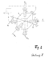
- Figure 1 shows the ball valve once in position I.
- the main current P1, P2 is interrupted and that inflowing medium is transferred from port A to port C passed from there into a valve or pump X1 and back into the ball valve via connection piece F to the nozzle D, which in turn to the central main line P2 leads.
- the ball is swiveled 180 degrees into the Position II gives the following situation:
- the main current P1, P2 is interrupted and is by Port A via port E to the valve or pump X2 headed. From there it comes back via nozzle B. Connection D and thus back into the main power line P2.
- the conveying direction can also change after switching be in the opposite direction.
- the ball valve is at Connection to a pump 10 shown.
- the pump 10 supports constantly in the same direction and depending on the position of the actuator is in one of the ports C and D Direction and in the opposite direction of the Main pipeline promoted.
- the housing can consist of two parts, the Pitch is perpendicular to the axis of rotation 2.
Landscapes
- Engineering & Computer Science (AREA)
- General Engineering & Computer Science (AREA)
- Mechanical Engineering (AREA)
- Multiple-Way Valves (AREA)
- Taps Or Cocks (AREA)
- Fuel-Injection Apparatus (AREA)
- External Artificial Organs (AREA)
- Temperature-Responsive Valves (AREA)
Abstract
Description
Die Erfindung betrifft einen Kugelhahn mit einem im Hahngehäuse gelagerten kugelförmigen Stellglied und Ein- und Auslässen in der Wandung des Gehäuseinnenraumes, der das Stellglied aufnimmt.The invention relates to a ball valve with a Spherical actuator and and outlets in the wall of the housing interior, the the actuator receives.
Aus der DE-A-3 702 598 ist ein derartiger Kugelhahn bekannt, der eine Mehrfachverteilfunktion übernimmt. Die Drehachse des kugelförmigen Stellgliedes verläuft bei diesem Mehrfachverteiler durch eine Auslaßleitung, der aus verschiedenen Einlässen durch Drehung des Stellgliedes Flüssigkeiten oder Gase zugeführt werden können. Hierzu liegen sämtliche Einlaßleitungen auf einer Ebene, die senkrecht zur Drehachse verläuft. Da alle Einlaßleitungen nur eine gemeinsame Auslaßleitung haben, ist die Variabilität dieses Mehrfachverteilers eingeschränkt.Such a ball valve is known from DE-A-3 702 598 known that takes over a multiple distribution function. The The axis of rotation of the spherical actuator runs at this manifold through an outlet line, the from different inlets by rotating the Actuator liquids or gases are supplied can. For this purpose, all inlet lines are on one Plane that is perpendicular to the axis of rotation. Since all Inlet lines only have one common outlet line, is the variability of this multiple distributor limited.
Bei flüssigkeits- und gasfördernden Anlagen, in denen
Pumpen und Armaturen installiert sind, gibt es häufig die
Anforderung, einen ankommenden Förderstrom wechselweise
in eine erste und alternativ dazu, in eine zweite Armatur
oder Pumpe zu leiten und anschließend wieder in die
Hauptleitung zurückzuführen. Üblicherweise wird eine
solche Wechselschaltung konventionell installiert, d.h.
mit zwei Hosenrohren und mehreren Absperreinrichtungen
(in der Regel 4) werden die alternativ einsetzbaren
Armaturen oder Pumpen mit der Hauptrohrleitung verbunden.
Es sind auch Wechselventile bekannt (DD 293 177 A5), die
diesen Installationsaufwand reduzieren helfen. Allerdings
sind diese Ausführungen, wie z.B. Doppelventile oder
Drehschieberventile sehr aufwendig und kostspielig
aufgebaut.
Bei Armaturen, die mit Auskleidungen aus Kunststoffen
versehen sind (z.B. im hochkorrosiven Bereich), sind
solche Doppelventile oder Drehschieberventile technisch
und wirtschaftlich nicht realisierbar.In the case of liquid and gas pumping systems in which pumps and fittings are installed, there is often a requirement to alternately feed an incoming flow into a first fitting or, alternatively, into a second fitting or pump and then return it to the main line. Such a two-way circuit is usually installed conventionally, ie the alternative fittings or pumps are connected to the main pipeline with two downpipes and several shut-off devices (usually 4). Change-over valves are also known (DD 293 177 A5), which help to reduce this installation effort. However, these designs, such as double valves or rotary slide valves, are very complex and costly.
In valves that are lined with plastics (e.g. in the highly corrosive area), such double valves or rotary slide valves are technically and economically not feasible.
Aufgabe der Erfindung ist es, einen Kugelhahn zu schaffen, durch den bei einfacher Konstruktion und Handhabung die unterschiedlichsten Verbindungen zwischen einer hohen Zahl von Anschlüssen schaffbar sind.The object of the invention is to provide a ball valve create through the simple construction and Handling the most diverse connections between a large number of connections can be created.
Diese Aufgabe wird erfindungsgemäß dadurch gelöst, daß die Wandung des Gehäuseinnenraumes mindestens sechs Ein- bzw. Auslässe aufweist und jeder Ein- bzw. Auslaß (a, c, e) mit einem anderen Ein- bzw. Auslaß (b, d, f) fluchtet und die Drehachse, um die das kugelförmige Stellglied drehverstellbar ist, zwischen den Ein- und Auslässen verläuft.This object is achieved in that the wall of the housing interior has at least six or has outlets and each inlet or outlet (a, c, e) is aligned with another inlet or outlet (b, d, f) and the axis of rotation about which the spherical actuator is rotatable between the inlets and outlets runs.
Ein solcher Kugelwechselhahn weist, beispielsweise jeweils 90 Grad versetzt, mehrere, insbesondere 6 Anschlußflansche auf. Die Kugel ist mindestens zu einer Hauptachse im Winkel von ca. 45 Grad drehbar gelagert und weist mindestens einen inneren Kanal, vorzugsweise zwei bis drei innere Kanäle auf, die jeweils zwei Anschlußstutzen verbinden.Such a ball valve has, for example each offset 90 degrees, several, especially 6 Connection flanges. The ball is at least one The main axis can be rotated at an angle of approx. 45 degrees has at least one inner channel, preferably two to three inner channels, two each Connect the connecting piece.
Der Kugelhahn kann das strömende Medium einer Hauptstromleitung alternativ in zwei unterschiedliche Armaturen bzw. Pumpen umlenken und wieder auf die Hauptleitung zurückführen, und zwar in einer Form, daß die nicht im Eingriff befindliche Armatur oder Pumpe von der Hauptstromleitung dicht abgesperrt ist. Diese Funktion wird in einer einzigen Armatur realisiert, was eine sehr große Rationalisierung der Bauteilkosten bei der Installation und bei der eventuellen Automatisierung der Wechsel-Funktion bedeutet.The ball valve can be the flowing medium Main power line alternatively in two different Redirect fittings or pumps and back on the Return main line in a form that the valve or pump from the main power line is sealed off. This Function is realized in a single fitting, what a very large rationalization of component costs installation and possible automation the change function means.
In verschiedenen Installationen ist es notwendig, die Förderrichtung einer Pumpe umzukehren, um somit z.B. über einen bestimmten Zeitraum in einen Behälter, Mischer o.ä. hineinzufördern und anschließend wieder herauszufördern. Aufgrund der Kompliziertheit der Installation werden hierzu häufig zwei separate Pumpen installiert. Mit dem dargestellten Kugelwechselhahn ist es möglich, durch 180 Grad-Verstellung einer einzigen Armatur die Förderrichtung einer Pumpe umzukehren, siehe Figuren 4 und 5.In various installations it is necessary to Reverse the delivery direction of a pump, e.g. about a certain period of time in a container, mixer or similar. convey in and then convey out again. Due to the complexity of the installation often two separate pumps installed. With the Ball valve shown, it is possible to use 180 Degree adjustment of a single fitting Reverse delivery direction of a pump, see Figure 4 and 5.
Vorteilhafte Ausgestaltungen der Erfindung sind in den Unteransprüchen aufgeführt.Advantageous embodiments of the invention are in the Subclaims listed.
Ein Ausführungsbeispiel der Erfindung ist in den Zeichnungen dargestellt und wird im folgenden näher beschrieben. Es zeigen:
- Figur 1:
- Eine perspektivische schematische Darstellung des Kugelventils in einer ersten Hahnstellung.
- Figur 2:
- Das Kugelventil nach Figur 1 in einer zweiten Hahnstellung.
- Figur 3:
- Schnitte durch den Kugelhahn in zwei Stellungen bei schematisch dargstelltem Gehäuse und
Figur 4 und 5 :- zwei schematische Darstellungen des an einer Pumpe angeschlossenen Kugelventils, das durch seine zwei Ventilstellungen zwei unterschiedliche Förderrichtungen erzeugt.
- Figure 1:
- A perspective schematic representation of the ball valve in a first tap position.
- Figure 2:
- The ball valve of Figure 1 in a second tap position.
- Figure 3:
- Cuts through the ball valve in two positions with the housing and shown schematically
- Figure 4 and 5:
- two schematic representations of the ball valve connected to a pump, which generates two different delivery directions due to its two valve positions.
Der Kugelhahn weist ein kugelförmiges Stellglied 1 bzw.
Küken auf, das um eine Achse 2 drehverstellbar in dem
Innenraum 3 eines Hahngehäuses 4 gelagert ist. Die
kugelförmige Innenwand 5 des Innenraums 3 oder nicht
dargestellte Sitzringe liegen direkt an dem Stellglied 1
an. Die Innenwand 5 bildet sechs Ein- bzw. Auslässe a bis
f, an die sechs Anschlußstutzen A bis F sich
anschließen.The ball valve has a spherical actuator 1 or
Chick on which is rotatable about an
Je zwei Ein- bzw. Auslässe a bis f liegen mit ihren
Anschlußstutzen A bis F paarweise auf je einer Achse A1,
A2 und A3, die zueinander jeweils in einem Winkel von 90
Grad stehen und einander im Mittelpunkt 6 des Stellglieds
1 schneiden. Durch den Mittelpunkt 6 verläuft auch die
schräg liegende Drehachse 2 des Stellgliedes. Hierbei
bildet die Drechachse 2 mit den Achsen mindestens einer
Hauptachse (A1, A2, A3) jeweils einen Winkel von 45 Grad.Two inlets and outlets a to f are located with their
Connection pieces A to F in pairs on an axis A1,
A2 and A3, each at an angle of 90
Stand degrees and each other in the center 6 of the actuator
1 cut. Through the center 6 also runs
oblique axis of
Im Innern des Stellglieds 1 sind im Ausführungsbeispiel
nur zwei Verbindungskanäle 8, 9 eingeformt. Jeder dieser
zwei Kanäle 8, 9 ist gekrümmt ausgeführt und verläuft
bogenförmig, so daß ein Kanal niemals zwei Ein- bzw.
Auslässe auf derselben Achse A1, A2, A3 verbindet,
sondern stets einen Ein- bzw. Auslaß einer Achse mit dem
Ein- bzw. Auslaß einer anderen Achse verbindet. Inside the actuator 1 are in the embodiment
only two connecting
Figur 1 zeigt den Kugelwechselhahn einmal in der Stellung I. Hierbei ist der Hauptstrom P1, P2 unterbrochen und das einströmende Medium wird vom Stutzen A auf Stutzen C geleitet, von dort in eine Armatur oder Pumpe X1 und wieder zurück in den Kugelwechselhahn über den Stutzen F zum Stutzen D, der wiederum zur zentralen Hauptleitung P2 führt. Bei einer Schwenkung der Kugel um 180 Grad in die Stellung II ergibt sich folgende Situation:Figure 1 shows the ball valve once in position I. Here, the main current P1, P2 is interrupted and that inflowing medium is transferred from port A to port C passed from there into a valve or pump X1 and back into the ball valve via connection piece F to the nozzle D, which in turn to the central main line P2 leads. When the ball is swiveled 180 degrees into the Position II gives the following situation:
Der Hauptstrom P1, P2 ist unterbrochen und wird von Stutzen A über Stutzen E zur Armatur bzw. Pumpe X2 geleitet. Von dort gelangt er zurück über Stutzen B zu Stutzen D und damit wieder in die Hauptstromleitung P2. Hierbei kann die Förderrichtung nach dem Umschalten auch in entgegengesetzter Richtung sein.The main current P1, P2 is interrupted and is by Port A via port E to the valve or pump X2 headed. From there it comes back via nozzle B. Connection D and thus back into the main power line P2. The conveying direction can also change after switching be in the opposite direction.
In den Figuren 4 und 5 ist der Kugelwechselhahn beim Anschluß an eine Pumpe 10 dargestellt. Die Pumpe 10 fördert ständig in dieselbe Richtung und je nach Stellung des Stellglieds wird über die Stutzen C und D in die eine Richtung und in die entgegengesetzte Richtung der Hauptrohrleitung gefördert.In Figures 4 and 5, the ball valve is at Connection to a pump 10 shown. The pump 10 supports constantly in the same direction and depending on the position of the actuator is in one of the ports C and D Direction and in the opposite direction of the Main pipeline promoted.
Das Gehäuse kann aus zwei Teilen bestehen, deren
Teilungsebene rechtwinklig zur Drehachse 2 liegt.The housing can consist of two parts, the
Pitch is perpendicular to the axis of
Claims (8)
- A ball valve having a spherical plug (1) mounted in the valve casing (4) and also inlets and outlets (a-f) in the wall (5) of the casing inner chamber (3) which receives the plug (1),
characterised in that the wall of the casing inner chamber (3) has at least six inlets/outlets (a-f) and each inlet/outlet (a, c, e) is aligned with another inlet/outlet (b, d, f), and
the axis of rotation (2) around which the spherical plug can be rotatably adjusted extends between the inlets and outlets. - A ball valve according to claim 1,
characterised in that the inlets/outlets (a-f) are disposed in pairs on an axis (A1, A2, A3). - A ball valve according to claims 1 or 2,
characterised in that the three axes (A1, A2, A3) all form an angle of 90°. - A ball valve according to one of the preceding claims,
characterised in that the axis of rotation (2) of the plug lies at an inclination to at least main axis (A1, A2, A3). - A ball valve according to one of the preceding claims,
characterised in that the axis of rotation (2) forms an angle of 45° with at least one main axis (A1, A2, A3). - A ball valve according to one of the preceding claims,
characterised in that disposed in the valve plug (1) are two channels (8, 9) which connect the inlets/outlets (a-f) optionally to one another. - A ball valve according to claim 6,
characterised in that the channels disposed in the valve plug (1) are constructed curved and connect the inlet or outlet lying on one axis to the outlet or inlet lying on another axis. - A ball valve according to one of the preceding claims,
characterised in that the division of the casing lies transversely of the axis of rotation (2).
Applications Claiming Priority (4)
| Application Number | Priority Date | Filing Date | Title |
|---|---|---|---|
| DE4442984 | 1994-12-02 | ||
| DE4442984 | 1994-12-02 | ||
| DE19525062 | 1995-07-10 | ||
| DE19525062A DE19525062A1 (en) | 1994-12-02 | 1995-07-10 | Ball valve |
Publications (2)
| Publication Number | Publication Date |
|---|---|
| EP0715105A1 EP0715105A1 (en) | 1996-06-05 |
| EP0715105B1 true EP0715105B1 (en) | 2000-01-19 |
Family
ID=25942524
Family Applications (1)
| Application Number | Title | Priority Date | Filing Date |
|---|---|---|---|
| EP95117203A Expired - Lifetime EP0715105B1 (en) | 1994-12-02 | 1995-11-02 | Ball valve |
Country Status (3)
| Country | Link |
|---|---|
| EP (1) | EP0715105B1 (en) |
| AT (1) | ATE189045T1 (en) |
| DK (1) | DK0715105T3 (en) |
Families Citing this family (3)
| Publication number | Priority date | Publication date | Assignee | Title |
|---|---|---|---|---|
| KR100867157B1 (en) | 2007-04-30 | 2008-11-06 | 주식회사 금오하이텍 | Energy-saving hot water distribution devic |
| FR2998634B1 (en) * | 2012-11-27 | 2015-10-23 | Ge Energy Products France Snc | SPHERICAL SHUTTER VALVE, IN PARTICULAR FOR GAS TURBINE |
| CN109720667B (en) * | 2019-02-22 | 2020-07-31 | 莱芜职业技术学院 | Automatic change fertilizer filling system |
Family Cites Families (6)
| Publication number | Priority date | Publication date | Assignee | Title |
|---|---|---|---|---|
| US3370612A (en) * | 1964-10-19 | 1968-02-27 | Robert W. Holl | Four-way ball valve |
| US4212321A (en) * | 1979-04-09 | 1980-07-15 | J. R. Butler | Low noise rotary control valve |
| IT1184085B (en) * | 1985-04-16 | 1987-10-22 | Agip Petroli | PERFECTED INTERCEPTION VALVE AND SELECTION OF THE BALL TYPE AND GROUP VALVE USING THE SAME |
| DE3702598A1 (en) * | 1987-01-29 | 1988-08-11 | Em Technik Gmbh Armaturenbau | Multiway distributor cock |
| HU210511B (en) | 1989-02-15 | 1995-04-28 | Viktoria Elsoe Magyar Gabona R | Fitting-set mainly for pipes used at milling industry |
| DE4235723A1 (en) * | 1992-10-23 | 1994-04-28 | Em Technik Gmbh Armaturenbau | Multi-way ball cock for gases and fluids - has two balls connected together rotationally secured by spacer adjoining bore in housing containing balls |
-
1995
- 1995-11-02 EP EP95117203A patent/EP0715105B1/en not_active Expired - Lifetime
- 1995-11-02 AT AT95117203T patent/ATE189045T1/en not_active IP Right Cessation
- 1995-11-02 DK DK95117203T patent/DK0715105T3/en active
Also Published As
| Publication number | Publication date |
|---|---|
| EP0715105A1 (en) | 1996-06-05 |
| ATE189045T1 (en) | 2000-02-15 |
| DK0715105T3 (en) | 2000-06-26 |
Similar Documents
| Publication | Publication Date | Title |
|---|---|---|
| DE69110630T2 (en) | Dispensing devices with multi-way valve. | |
| EP0399344B1 (en) | Valve | |
| DE69605307T2 (en) | DEVICE FOR DISTRIBUTING FLOW | |
| EP2126426B1 (en) | Combination valve | |
| DE69201830T2 (en) | Piggy 3-way flap valve. | |
| DE60128717T2 (en) | FOUR WAY VALVE | |
| DE3826064C2 (en) | ||
| EP0715105B1 (en) | Ball valve | |
| EP1649201B2 (en) | Multiport valve | |
| DE4210659C2 (en) | Multi-way valve with piggable passage | |
| DE19525062A1 (en) | Ball valve | |
| DE19735893A1 (en) | Filter fittings arrangement for drinking water | |
| DE3743052C2 (en) | Turning element for the connections in water fittings | |
| DE19740392A1 (en) | Fourway cock with housing with four inlets or outlets | |
| DE10214242A1 (en) | Multi-path mixer valve for flow medium has inlets and outlets, valve cock in valve housing which is cruciform and has flow ducts in center and ends of arms | |
| DE10007072B4 (en) | Multi-way valve and system with such a multi-way valve | |
| EP0480974A1 (en) | Distributor device. | |
| EP0359901B1 (en) | Mixing device for a hot water heating installation | |
| DE4305694A1 (en) | Distribution unit for heating or cooling systems working with a fluid heat transfer medium | |
| EP0240860B1 (en) | Heating furnace | |
| DD293177A5 (en) | ARMATURFAMILIE, ESPECIALLY FOR PIPES OF THE MUEHLINDUSTRIE | |
| DE1750787A1 (en) | Piggable transfer tube | |
| DE2212763C2 (en) | SWITCHING AND MIXING VALVE | |
| EP1529752B1 (en) | Valve device for mixing beverages | |
| DE69407401T2 (en) | VALVE |
Legal Events
| Date | Code | Title | Description |
|---|---|---|---|
| PUAI | Public reference made under article 153(3) epc to a published international application that has entered the european phase |
Free format text: ORIGINAL CODE: 0009012 |
|
| 17P | Request for examination filed |
Effective date: 19960323 |
|
| AK | Designated contracting states |
Kind code of ref document: A1 Designated state(s): AT BE CH DE DK FR GB IT LI LU NL |
|
| 17Q | First examination report despatched |
Effective date: 19980828 |
|
| GRAG | Despatch of communication of intention to grant |
Free format text: ORIGINAL CODE: EPIDOS AGRA |
|
| GRAG | Despatch of communication of intention to grant |
Free format text: ORIGINAL CODE: EPIDOS AGRA |
|
| GRAH | Despatch of communication of intention to grant a patent |
Free format text: ORIGINAL CODE: EPIDOS IGRA |
|
| GRAH | Despatch of communication of intention to grant a patent |
Free format text: ORIGINAL CODE: EPIDOS IGRA |
|
| GRAA | (expected) grant |
Free format text: ORIGINAL CODE: 0009210 |
|
| AK | Designated contracting states |
Kind code of ref document: B1 Designated state(s): AT BE CH DE DK FR GB IT LI LU NL |
|
| REF | Corresponds to: |
Ref document number: 189045 Country of ref document: AT Date of ref document: 20000215 Kind code of ref document: T |
|
| REG | Reference to a national code |
Ref country code: CH Ref legal event code: NV Representative=s name: SCHMAUDER & PARTNER AG PATENTANWALTSBUERO Ref country code: CH Ref legal event code: EP |
|
| GBT | Gb: translation of ep patent filed (gb section 77(6)(a)/1977) |
Effective date: 20000119 |
|
| REF | Corresponds to: |
Ref document number: 59507644 Country of ref document: DE Date of ref document: 20000224 |
|
| ITF | It: translation for a ep patent filed | ||
| ET | Fr: translation filed | ||
| REG | Reference to a national code |
Ref country code: DK Ref legal event code: T3 |
|
| PLBE | No opposition filed within time limit |
Free format text: ORIGINAL CODE: 0009261 |
|
| STAA | Information on the status of an ep patent application or granted ep patent |
Free format text: STATUS: NO OPPOSITION FILED WITHIN TIME LIMIT |
|
| 26N | No opposition filed | ||
| REG | Reference to a national code |
Ref country code: GB Ref legal event code: IF02 |
|
| PGFP | Annual fee paid to national office [announced via postgrant information from national office to epo] |
Ref country code: NL Payment date: 20051016 Year of fee payment: 11 |
|
| PGFP | Annual fee paid to national office [announced via postgrant information from national office to epo] |
Ref country code: GB Payment date: 20051026 Year of fee payment: 11 |
|
| PGFP | Annual fee paid to national office [announced via postgrant information from national office to epo] |
Ref country code: CH Payment date: 20051125 Year of fee payment: 11 |
|
| PGFP | Annual fee paid to national office [announced via postgrant information from national office to epo] |
Ref country code: DK Payment date: 20051129 Year of fee payment: 11 |
|
| PGFP | Annual fee paid to national office [announced via postgrant information from national office to epo] |
Ref country code: BE Payment date: 20051208 Year of fee payment: 11 |
|
| PGFP | Annual fee paid to national office [announced via postgrant information from national office to epo] |
Ref country code: LU Payment date: 20051229 Year of fee payment: 11 |
|
| PGFP | Annual fee paid to national office [announced via postgrant information from national office to epo] |
Ref country code: AT Payment date: 20061019 Year of fee payment: 12 |
|
| PGFP | Annual fee paid to national office [announced via postgrant information from national office to epo] |
Ref country code: FR Payment date: 20061117 Year of fee payment: 12 |
|
| PG25 | Lapsed in a contracting state [announced via postgrant information from national office to epo] |
Ref country code: LI Free format text: LAPSE BECAUSE OF NON-PAYMENT OF DUE FEES Effective date: 20061130 Ref country code: DK Free format text: LAPSE BECAUSE OF NON-PAYMENT OF DUE FEES Effective date: 20061130 Ref country code: CH Free format text: LAPSE BECAUSE OF NON-PAYMENT OF DUE FEES Effective date: 20061130 Ref country code: BE Free format text: LAPSE BECAUSE OF NON-PAYMENT OF DUE FEES Effective date: 20061130 |
|
| PGFP | Annual fee paid to national office [announced via postgrant information from national office to epo] |
Ref country code: IT Payment date: 20061130 Year of fee payment: 12 |
|
| PG25 | Lapsed in a contracting state [announced via postgrant information from national office to epo] |
Ref country code: NL Free format text: LAPSE BECAUSE OF NON-PAYMENT OF DUE FEES Effective date: 20070601 |
|
| REG | Reference to a national code |
Ref country code: DK Ref legal event code: EBP |
|
| REG | Reference to a national code |
Ref country code: CH Ref legal event code: PL |
|
| GBPC | Gb: european patent ceased through non-payment of renewal fee |
Effective date: 20061102 |
|
| NLV4 | Nl: lapsed or anulled due to non-payment of the annual fee |
Effective date: 20070601 |
|
| PG25 | Lapsed in a contracting state [announced via postgrant information from national office to epo] |
Ref country code: GB Free format text: LAPSE BECAUSE OF NON-PAYMENT OF DUE FEES Effective date: 20061102 |
|
| BERE | Be: lapsed |
Owner name: *ITT RICHTER CHEMIE-TECHNIK G.M.B.H. Effective date: 20061130 |
|
| PG25 | Lapsed in a contracting state [announced via postgrant information from national office to epo] |
Ref country code: LU Free format text: LAPSE BECAUSE OF NON-PAYMENT OF DUE FEES Effective date: 20061102 |
|
| PG25 | Lapsed in a contracting state [announced via postgrant information from national office to epo] |
Ref country code: AT Free format text: LAPSE BECAUSE OF NON-PAYMENT OF DUE FEES Effective date: 20071102 |
|
| REG | Reference to a national code |
Ref country code: FR Ref legal event code: ST Effective date: 20080930 |
|
| PGFP | Annual fee paid to national office [announced via postgrant information from national office to epo] |
Ref country code: DE Payment date: 20081103 Year of fee payment: 14 |
|
| PG25 | Lapsed in a contracting state [announced via postgrant information from national office to epo] |
Ref country code: FR Free format text: LAPSE BECAUSE OF NON-PAYMENT OF DUE FEES Effective date: 20071130 |
|
| PG25 | Lapsed in a contracting state [announced via postgrant information from national office to epo] |
Ref country code: IT Free format text: LAPSE BECAUSE OF NON-PAYMENT OF DUE FEES Effective date: 20071102 |
|
| PG25 | Lapsed in a contracting state [announced via postgrant information from national office to epo] |
Ref country code: DE Free format text: LAPSE BECAUSE OF NON-PAYMENT OF DUE FEES Effective date: 20100601 |