EP0714362B1 - Propulsion system for a lighter-than-air vehicle - Google Patents
Propulsion system for a lighter-than-air vehicle Download PDFInfo
- Publication number
- EP0714362B1 EP0714362B1 EP94924133A EP94924133A EP0714362B1 EP 0714362 B1 EP0714362 B1 EP 0714362B1 EP 94924133 A EP94924133 A EP 94924133A EP 94924133 A EP94924133 A EP 94924133A EP 0714362 B1 EP0714362 B1 EP 0714362B1
- Authority
- EP
- European Patent Office
- Prior art keywords
- pylon
- assembly
- vehicle
- thrust
- combination
- Prior art date
- Legal status (The legal status is an assumption and is not a legal conclusion. Google has not performed a legal analysis and makes no representation as to the accuracy of the status listed.)
- Expired - Lifetime
Links
- 230000005540 biological transmission Effects 0.000 claims description 9
- 230000002441 reversible effect Effects 0.000 claims description 4
- 238000003032 molecular docking Methods 0.000 description 10
- 230000000712 assembly Effects 0.000 description 9
- 238000000429 assembly Methods 0.000 description 9
- 238000013461 design Methods 0.000 description 6
- 230000008901 benefit Effects 0.000 description 2
- 239000007789 gas Substances 0.000 description 2
- 230000007246 mechanism Effects 0.000 description 2
- 238000000034 method Methods 0.000 description 2
- RZVHIXYEVGDQDX-UHFFFAOYSA-N 9,10-anthraquinone Chemical compound C1=CC=C2C(=O)C3=CC=CC=C3C(=O)C2=C1 RZVHIXYEVGDQDX-UHFFFAOYSA-N 0.000 description 1
- 238000013459 approach Methods 0.000 description 1
- 239000000446 fuel Substances 0.000 description 1
- 239000001307 helium Substances 0.000 description 1
- 229910052734 helium Inorganic materials 0.000 description 1
- SWQJXJOGLNCZEY-UHFFFAOYSA-N helium atom Chemical compound [He] SWQJXJOGLNCZEY-UHFFFAOYSA-N 0.000 description 1
- 230000001939 inductive effect Effects 0.000 description 1
- 238000012423 maintenance Methods 0.000 description 1
- 238000012986 modification Methods 0.000 description 1
- 230000004048 modification Effects 0.000 description 1
- 230000008520 organization Effects 0.000 description 1
- 230000008439 repair process Effects 0.000 description 1
Images


Classifications
-
- B—PERFORMING OPERATIONS; TRANSPORTING
- B64—AIRCRAFT; AVIATION; COSMONAUTICS
- B64B—LIGHTER-THAN AIR AIRCRAFT
- B64B1/00—Lighter-than-air aircraft
- B64B1/06—Rigid airships; Semi-rigid airships
- B64B1/24—Arrangement of propulsion plant
- B64B1/30—Arrangement of propellers
-
- B—PERFORMING OPERATIONS; TRANSPORTING
- B64—AIRCRAFT; AVIATION; COSMONAUTICS
- B64B—LIGHTER-THAN AIR AIRCRAFT
- B64B1/00—Lighter-than-air aircraft
- B64B1/06—Rigid airships; Semi-rigid airships
- B64B1/24—Arrangement of propulsion plant
- B64B1/30—Arrangement of propellers
- B64B1/34—Arrangement of propellers of lifting propellers
Definitions
- the invention relates to the field of propulsion systems for lighter-than-air vehicles and, in particular, to a propulsion system that provides maneuvering and thrust vectoring control.
- non-rigid vehicles there are three general types of non-rigid vehicles: those comprising a single gas filled bag; several gasbags joined together in series; and, of course, those having a multiple number gasbags within a non-rigid envelope.
- a particular problem with such non-rigid vehicles is that, because of the lack of rigid structure within the gas bag, the placement of the thrust assemblies is limited to the gondola. Thus, because the gondola is suspended from the bottom of the vehicle, any maneuvering forces generated by the propulsion system can not act through the center of pressure of the vehicle and, therefore, their effectiveness is reduced.
- rigid airships that have an internal structure defining the shape of the vehicle that contain a plurality of gasbags with an aerodynamic cover thereover.
- the propulsion system can be mounted almost anywhere on the rigid structure, they are most often mounted at or near the bottom of the vehicle for ease of access, etc. Thus what is needed is a propulsion system wherein all these control problems are addressed while inducing a minimum weight addition to the vehicle.
- the propulsion system provides for the repositioning of the thrust producing assemblies, such as ducted and unducted fans or propellers, preferably so that side thrust can be provided without exhaust therefrom striking the gasbag of the vehicle.
- the thrust producing assemblies can be positioned so as not to interfere with ground handling equipment when docking.
- the invention relates to a lighter-than-air vehicle, of either the rigid or non-rigid type, having a longitudinal, horizontal and vertical axis, having a propulsion system.
- a lighter-than-air vehicle of either the rigid or non-rigid type, having a longitudinal, horizontal and vertical axis, having a propulsion system.
- the cargo compartment and flight control station are suspended from the gasbag and, therefore, are called a gondola.
- rigid vehicles such structure can be integrated and need not be suspended.
- the cargo compartment and flight station shall be referred to as the "cargo structure".
- Each propulsion system includes a thrust producing assembly that can be a fan, ducted fan, propeller, or ducted propeller.
- ducted fans or propellers are preferred from a safety standpoint for if there is a blade failure, the duct wall would prevent the blade from possibly ripping open the gasbag.
- the thrust assembly could also be a turbofan engine; however, due to the extremely low cruise speed of such vehicles, less than 160 km/h (100 miles per hour), and the need for high fuel efficiency, they are not often used in such applications.
- the thrust assembly is mounted on the end of a pylon that, in the cruise position, extends horizontally outward from the vehicle perpendicular to the longitudinal axis. If the vehicle is a non-rigid type, the pylon is attached to the gondola. On a rigid design, it is possible to attach the pylon to the main support structure; however, even with rigid designs, it is more desirable to attach the thrust producing assemblies on the cargo compartment to provide ease of access for maintenance, repair and removal. This is particularly true if the vehicle is extremely large.
- the thrust assembly is rotatably mounted on the free end of the pylon, rotatable about an axis of rotation in a plane perpendicular to the longitudinal axis of the pylon.
- a lighter-than-air vehicle as described above is disclosed in GB-A-2250007, which has the feature of the preamble of claim 1 set out below.
- the pylon is rotatably mounted to the vehicle such that the thrust assembly can be positioned by a second actuation system upward and downward from the horizontal.
- a second actuation system upward and downward from the horizontal.
- this is a jack screw assembly mounted on the vehicle with the end of the jack screw attached to the pylon.
- Upward positioning is desirable in order to clear ground support equipment when the vehicle is docked.
- the downward position is desirable when the thrust assembly is rotated at ninety degrees to provide side and downward directed thrust.
- the adjusting of the thrust assembly to provide downward thrust in conjunction with the positioning of the pylon in the downward position, allows the exhaust to be directed at an angle so as to miss the gasbag. This is particularly advantageous when the thrust assembly is mounted on the cargo structure below the gasbag and thus positioned well under.
- the rotation of the thrust assembly on the free end of the pylon is such that the thrust assembly is rotatable from a position wherein the thrust is directed forward to a position wherein the thrust is directed backwards, that is rotatable plus or minus one-hundred and eighty (180) degrees.
- thrust can be directed vertically upward, vertically downward and to the rear.
- rotation could be limited to a plus or minus ninety (90) degrees.
- Rotation of the thrust assemblies is accomplished by a first actuation assembly mounted on the end of the pylon.
- a suitable first actuation assembly comprises a ring gear mounted on the thrust assembly engaging a pinon gear attached to the output shaft of a hydraulic or electrical motor mounted on the pylon.
- the use of such a gear assembly allows for the "locking" of the thrust assembly in any selected position; however, other mechanisms can be used.
- the thrust axis of the thrust assemblies can be individually positioned to provide a wide variety of combinations as a further aid in maneuvering the vehicle.
- the power to the thrust assembly is provided by a powerplant mounted on the vehicle, in the case of a non-rigid airship, in the gondola structure.
- the powerplant is coupled to the thrust assembly via drive shafts and universal joints and a transmission assembly so that rotation of the pylon and thrust assembly can be accomplished.
- This is particularly desirable because, since both the pylon and thrust assembly can be rotated, having the powerplant mounted at the end of the pylon could add a significant weight penalty.
- mounting the powerplant in the cargo structure provides much easier access thereto. The advantage of this method of mounting can be readily seen if the vehicle is extremely large. For example in a non-rigid airship having a 450kt (million pound) payload, the vehicle is over (300m) (1000 feet) in length and 80m (260 feet) in diameter. Six ducted fans having 5.5m (18 foot) diameter blades are required with each fan driven by two 150kW (2000 shaft horsepower) diesel engines. Rotating the pylon and/or the ducted fans with the two diesel engines directly attached to the fan would incur an extremely large weight penalty.
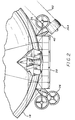
- FIG. 1 and 2 Illustrated in Figures 1 and 2 is a lighter-than-air vehicle and propulsion system according to the invention.
- the vehicle designated by numeral 10, is a non-rigid design having a longitudinal axis 12, vertical axis 14, and horizontal axis 16 and includes a helium bag 18 with a cargo structure 20, in the form of a gondola, mounted at the bottom.
- the propulsion system could also be use on a rigid vehicle design.
- a gondola type cargo compartment (suspended cargo compartment) is necessary on a non-rigid vehicle it is certainly not required on a rigid design.
- a gondola style cargo compartment is also for purposes of illustration only and, again, hereinafter generally referred to as a cargo structure.
- the vehicle 10 includes six separate propulsion systems 24 having thrust producing assemblies, in the form of ducted propellers 26 mounted along the cargo compartment 20, three on each side (only those on the left side are shown in Figure 1).
- thrust producing assemblies in the form of ducted propellers 26 mounted along the cargo compartment 20, three on each side (only those on the left side are shown in Figure 1).
- ducted fans 27, as well as unducted propeller and fans assemblies, 28 and 29, respectively could be substituted and, therefore, the use of ducted propellers, and the number of thrust assemblies for that matter, is for purposes of illustration only.
- propellers or fans can and, preferably, are reversible.
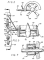
- each propulsion system 24 includes a pair of diesel engines 32A and 32B mounted on the floor 33 of the cargo compartment 20.
- the engines 32A and 32B have drive shafts 34A and 34B on a common centerline 36 that couple to a transmission assembly 38 rotatably mounted to the floor 33.
- a pylon 40 is coupled by its first end 42 to the transmission assembly 38 and by its second end 44 to the ducted propeller 26.
- the pylon 40 is hollow and contains a drive shaft 46 mounted therein that connects from the transmission assembly 38 to the ducted propeller 26 for driving same.
- a sway brace 52 is pivotally mounted by a first end 54 to the cargo compartment 30 on the centerline 36 of the drive shafts 34A and 34B, and by its second end 56 to the pylon 40 for reacting thrust loads on the pylon.
- An actuation assembly in the form of a jack screw 60 is mounted on the cargo compartment 20 having an end 62 of the screw attached to the pylon 40 for rotating the pylon about the centerline 36.
- the ducted propeller 26 includes individual propeller blades 64 rotatably mounted on a centerbody 66.
- the centerbody also supports the duct 68 by means of struts 70.
- the second end 44 of the pylon 40 extends through the duct 68 (the duct is rotatable thereabout) and couples to and supports the centerbody 66 by thrust bearings (not shown).
- the drive shaft 46 couples to a gearbox (not shown) that drives the propeller blades 64.
- Rotation of the ducted propeller is accomplished by a actuation assembly 74 mounted on the pylon that includes a motor 76 having a pinon gear 78 that engages a ring gear 80 attached to the duct 68.
- rotation of the ducted propeller 26 about the pylon 40 can be accomplished regardless of the pylon's position. If the ducted propeller is reversible, it need only rotate plus or minus 90 degrees; if not, it should be rotatable a full 180 degrees.
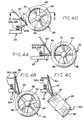
- the pylon 40 in operation, can be rotated from its cruise position 40 ( Figure 4A) to the docking or maneuvering position 40A ( Figure 4B) by actuation of the jack screw 60.
- the ducted propeller 26 can be rotated ninety degrees, indicated by numeral 26A ( Figure 4C), to provide both downward and side thrust or upward and side thrust, as desired.
- the exhaust indicated by numeral 82, misses the gasbag 18.
- the length and the angle of the pylon is rotated should be sufficient to allow the exhaust from the thrust assembly to miss the gasbag, when producing downward directed thrust.
- the pylon 40 When docking lines (not shown) are secured, the pylon 40 can be rotated upward to the docked position 40B ( Figure 4D), wherein the ducted propeller 26 is out of the way of any ground based docking structure (not shown). It should be noted that on the vehicle illustrated in Figure 1, there where six ducted propellers 26 incorporated and by independently adjusting the rotational position of each, as well as pylon 40 position, considerable latitude in thrust vectoring between ducted propellers is possible.
- the propulsion system can be used when the powerplant is integral with the thrust assembly, for example a turbofan engine.
- a pylon 110 having a longitudinal axis 111, is pivotally mounted to the cargo compartment 20 by its first end 112 and by its second end 114 to a turbofan engine 118.
- the actuation assembly 60 is used to rotate the pylon 110 and the actuation assembly 74 (shown in Figure 7 but not shown in Figure 8) is used to rotate the turbofan engine about the longitudinal axis 111 of the pylon 110.
Landscapes
- Engineering & Computer Science (AREA)
- Combustion & Propulsion (AREA)
- Mechanical Engineering (AREA)
- Aviation & Aerospace Engineering (AREA)
- Chemical & Material Sciences (AREA)
- Structures Of Non-Positive Displacement Pumps (AREA)
- Toys (AREA)
- Transmission Devices (AREA)
- Joints Allowing Movement (AREA)
- Pivots And Pivotal Connections (AREA)
- Vehicle Cleaning, Maintenance, Repair, Refitting, And Outriggers (AREA)
- Aiming, Guidance, Guns With A Light Source, Armor, Camouflage, And Targets (AREA)
- Support Of The Bearing (AREA)
- Air-Conditioning For Vehicles (AREA)
Description
Preferably the power to the thrust assembly is provided by a powerplant mounted on the vehicle, in the case of a non-rigid airship, in the gondola structure. The powerplant is coupled to the thrust assembly via drive shafts and universal joints and a transmission assembly so that rotation of the pylon and thrust assembly can be accomplished. This is particularly desirable because, since both the pylon and thrust assembly can be rotated, having the powerplant mounted at the end of the pylon could add a significant weight penalty. Additionally, mounting the powerplant in the cargo structure provides much easier access thereto. The advantage of this method of mounting can be readily seen if the vehicle is extremely large. For example in a non-rigid airship having a 450kt (million pound) payload, the vehicle is over (300m) (1000 feet) in length and 80m (260 feet) in diameter. Six ducted fans having 5.5m (18 foot) diameter blades are required with each fan driven by two 150kW (2000 shaft horsepower) diesel engines. Rotating the pylon and/or the ducted fans with the two diesel engines directly attached to the fan would incur an extremely large weight penalty.
Claims (11)
- A combination of a lighter-than-air vehicle (10) and a propulsion system therefor, the vehicle having a longitudinal axis (12), a horizontal axis (16) and a vertical axis (14), said propulsion system comprising:characterized by:a pylon (40; 110) having a longitudinal axis defined by first and second ends, said first end of said pylon being mounted to the vehicle and said second end extending outward from the vehicle,a thrust producing assembly (26, 27, 28, 29; 118) mounted on the second end of said pylon, said thrust producing assembly being rotatable about an axis of rotation in a plane perpendicular to the longitudinal axis of said pylon (40);said thrust producing assembly (26, 27, 28, 29; 118) being rotatable at least plus or minus ninety degrees in a plane perpendicular to the longitudinal axis of the pylon (40);a powerplant assembly (32A, 32B; 118) coupled to said thrust producing assembly, or integral therewith, to provide power thereto; andfirst means (74, 76, 78, 80) to rotate said thrust producing assembly about said axis of rotation;said pylon (40; 110) being rotatably mounted to the vehicle and being rotatable about said first end in a vertical plane perpendicular to the longitudinal axis of the vehicle in an upward and downward direction; andsecond means (60) to rotate said pylon (40) about said first end.
- The combination as set forth in claim 1, wherein said pylon (40; 110) is rotatable about said first end upward and downward from a plane parallel to the horizontal axis of the vehicle.
- The combination as set forth in claim 2, wherein said thrust producing assembly (26, 27, 28, 29; 118) is selected from the group consisting of fans, ducted fans, propellers and ducted propellers.
- The combination as set forth in claim 3, wherein said powerplant assembly is integral with said thrust producing assembly.
- The combination as set forth in claim 3, wherein said vehicle includes a cargo compartment (30) mounted on the bottom thereof, and wherein in said propulsion system:said powerplant assembly (32A) includes an engine mounted in said cargo compartment (30), said engine having a first output shaft (34A);a transmission assembly (38) is coupled to said first output shaft (34A) and has a second output shaft (46), said transmission assembly being rotatably mounted to the cargo compartment about an axis coincident with said axis of rotation of said pylon (40);said first end of said pylon is attached to said transmission assembly (38); andsaid second output shaft (46) is mounted within said pylon (40) and coupled to said thrust producing assembly (26, 26, 28, 29).
- The combination as set forth in claim 5, wherein:said powerplant assembly includes a second engine (32B) having a third output shaft (32B) having a third output shaft (34B), said second engine being mounted in said cargo compartment in a spaced relationship to said first mentioned engine, such that said first and third output shafts (34A, 34B) are on a common centerline; andsaid transmission assembly 938) is mounted between said first and second engines and also coupled to said third output shaft (34B), such that both engines drive said second output shaft (46) via said transmission.
- The combination as set forth in claim 6, wherein said means to rotate said thrust producing assembly about axis of rotation comprises:a ring gear (80) mounted on said thrust assembly; anda motor (76) mounted on said pylon (40), said pylon having a pinon gear (78) mounted thereon on engagement with said ring gear;such that rotation of said pinon gear by said motor causes said thrust producing assembly to rotate.
- The combination as set forth in claim 6, wherein said second means (60) comprises a jack screw mounted on said vehicle, said jack screw having an output shaft coupled to said pylon (40; 110), such that the extension and retraction of said output shaft causes said pylon to rotate downward and upward about said first end.
- The combination as set forth in claim 6, wherein said first and second engines are diesel engines.
- The combination as set forth in any one of claims 1-9, wherein said thrust producing assembly includes reversible thrust capability.
- The combination as set forth in any one of claims 1-9, wherein said thrust producing assembly is rotatable plus or minus one-hundred and eighty degrees.
Applications Claiming Priority (3)
| Application Number | Priority Date | Filing Date | Title |
|---|---|---|---|
| US08/108,280 US5368256A (en) | 1993-08-19 | 1993-08-19 | Propulsion system for a lighter-than-air vehicle |
| US108280 | 1993-08-19 | ||
| PCT/US1994/008827 WO1995005307A1 (en) | 1993-08-19 | 1994-08-03 | Propulsion system for a lighter-than-air vehicle |
Publications (3)
| Publication Number | Publication Date |
|---|---|
| EP0714362A1 EP0714362A1 (en) | 1996-06-05 |
| EP0714362A4 EP0714362A4 (en) | 1997-02-26 |
| EP0714362B1 true EP0714362B1 (en) | 2001-05-30 |
Family
ID=22321281
Family Applications (1)
| Application Number | Title | Priority Date | Filing Date |
|---|---|---|---|
| EP94924133A Expired - Lifetime EP0714362B1 (en) | 1993-08-19 | 1994-08-03 | Propulsion system for a lighter-than-air vehicle |
Country Status (16)
| Country | Link |
|---|---|
| US (1) | US5368256A (en) |
| EP (1) | EP0714362B1 (en) |
| JP (1) | JP3357059B2 (en) |
| KR (1) | KR100187545B1 (en) |
| CN (1) | CN1050332C (en) |
| AU (1) | AU674780B2 (en) |
| BR (1) | BR9406776A (en) |
| CA (1) | CA2165452C (en) |
| DE (1) | DE69427356T2 (en) |
| IL (1) | IL110469A (en) |
| MY (1) | MY111287A (en) |
| NZ (1) | NZ269748A (en) |
| RU (1) | RU2126341C1 (en) |
| SG (1) | SG55715A1 (en) |
| TW (1) | TW295567B (en) |
| WO (1) | WO1995005307A1 (en) |
Cited By (7)
| Publication number | Priority date | Publication date | Assignee | Title |
|---|---|---|---|---|
| USD583294S1 (en) | 2007-03-07 | 2008-12-23 | Lta Corporation | Airship |
| US7866601B2 (en) | 2006-10-20 | 2011-01-11 | Lta Corporation | Lenticular airship |
| US8297550B2 (en) | 2007-08-09 | 2012-10-30 | Lta Corporation | Lenticular airship and associated controls |
| USD670638S1 (en) | 2010-07-20 | 2012-11-13 | Lta Corporation | Airship |
| US8596571B2 (en) | 2011-03-31 | 2013-12-03 | Lta Corporation | Airship including aerodynamic, floatation, and deployable structures |
| US8894002B2 (en) | 2010-07-20 | 2014-11-25 | Lta Corporation | System and method for solar-powered airship |
| US9802690B2 (en) | 2013-11-04 | 2017-10-31 | Lta Corporation | Cargo airship |
Families Citing this family (22)
| Publication number | Priority date | Publication date | Assignee | Title |
|---|---|---|---|---|
| WO1996023693A1 (en) * | 1995-02-01 | 1996-08-08 | German Viktorovich Demidov | Vehicle with aerodynamic module |
| DE19700182A1 (en) * | 1997-01-04 | 1998-07-09 | Industrieanlagen Betriebsges | Aircraft with a fuselage designed essentially as an aerostatic buoyancy body |
| US6520824B1 (en) * | 1999-09-27 | 2003-02-18 | Toytronix | Balloon toy vehicle |
| KR20020015404A (en) * | 2000-08-22 | 2002-02-28 | 사태형 | Propelling equipment and balloon of airship |
| KR100453114B1 (en) * | 2001-11-27 | 2004-10-15 | 주식회사 한 지아이에스 | Method and device for position control of airship |
| KR100472560B1 (en) * | 2002-08-23 | 2005-03-08 | 한국항공우주연구원 | Thrust Vectoring System of Airship |
| DE102004005737A1 (en) * | 2004-02-05 | 2005-10-20 | Ludwig Bauch | Airship comprises a drive unit formed by a driving gear producing an air stream and supported on a support frame |
| US7540450B2 (en) * | 2004-07-16 | 2009-06-02 | Pratt & Whitney Canada Corp. | Aircraft propulsion system |
| JP2008520478A (en) * | 2004-09-08 | 2008-06-19 | ヤン,ビクター イェック | Solar powered levitation device for all types of vehicles (air, land and sea) |
| US20070102571A1 (en) * | 2005-10-20 | 2007-05-10 | Colting Hokan S | Airship for lifting heavy loads & methods of operation |
| US8322647B2 (en) | 2006-08-24 | 2012-12-04 | American Dynamics Flight Systems, Inc. | High torque aerial lift (HTAL) |
| CA2557893A1 (en) * | 2006-08-29 | 2008-02-29 | Skyhook International Inc. | Hybrid lift air vehicle |
| US7871035B2 (en) * | 2007-04-11 | 2011-01-18 | Hamilton Sundstrand Corporation | Propulsion system for an airship or hybrid aircraft |
| US7891603B2 (en) * | 2007-05-16 | 2011-02-22 | Michael Todd Voorhees | Differential thrust control system |
| US8245966B2 (en) * | 2009-02-04 | 2012-08-21 | 21St Century Airship Technologies Inc. | Airship and vectored propeller drive therefor |
| US8459589B2 (en) * | 2009-05-15 | 2013-06-11 | Lockheed Martin Corporation | External pressurization system for lighter than air vehicles |
| US8695919B2 (en) * | 2010-11-12 | 2014-04-15 | Sky Sapience Ltd. | Aerial unit and method for elevating payloads |
| CN102874400B (en) * | 2012-10-22 | 2015-08-12 | 湖南航天机电设备与特种材料研究所 | A kind of dirigible afterbody vectored thrust device |
| US10469021B2 (en) | 2016-10-17 | 2019-11-05 | Aetherix Corporation | Airborne renewable energy generation and storage |
| CN111114733B (en) * | 2019-12-26 | 2022-07-12 | 中国科学院光电研究院 | A high-altitude airship and its yaw control method |
| JP2022143589A (en) * | 2021-03-17 | 2022-10-03 | 康正 武藤 | Autonomous type flight body, and autonomous control method and autonomous controller therefor |
| WO2023002134A1 (en) * | 2021-07-21 | 2023-01-26 | Flying Whales | Electrically powered, rigid-structure airship and electric-power-generating nacelle equipping said airship |
Family Cites Families (18)
| Publication number | Priority date | Publication date | Assignee | Title |
|---|---|---|---|---|
| US1019635A (en) * | 1910-12-01 | 1912-03-05 | Frank Harlow | Adjustable propeller. |
| GB191502689A (en) * | 1915-02-19 | 1915-09-30 | Frank Henry Mccune | Improvements in Washing Machines. |
| US1277206A (en) * | 1918-01-02 | 1918-08-27 | George Fedchenko | Aeroplane. |
| US1677688A (en) * | 1927-03-22 | 1928-07-17 | Edward A Webb | Aircraft |
| DE505750C (en) * | 1928-11-20 | 1930-08-23 | Johann Schuette Dr | Drive for rigid airships with engines or popellers that can be swiveled into the ship's interior |
| US1879345A (en) * | 1929-04-15 | 1932-09-27 | Alvah H Lawrence | Dirigible air sailing craft |
| US1876153A (en) * | 1930-09-02 | 1932-09-06 | Schuyler O Spurrier | Aerial transportation apparatus |
| US1868976A (en) * | 1931-04-15 | 1932-07-26 | Charles S Hall | Aircraft propelling mechanism |
| FR808456A (en) * | 1935-10-24 | 1937-02-08 | Power lift and propulsion unit and aircraft fitted with this unit | |
| US3179354A (en) * | 1962-04-24 | 1965-04-20 | Alvarez-Calderon Alberto | Convertiplane and apparatus thereof |
| FR1551907A (en) * | 1966-08-11 | 1969-01-03 | ||
| DE1506586A1 (en) * | 1967-06-02 | 1969-10-09 | Entwicklungsring Sued Gmbh | Arrangement and design of extendable multiple jet engines |
| US3614034A (en) * | 1969-07-09 | 1971-10-19 | Fairchild Hiller Corp | V/stol aircraft |
| US4402475A (en) * | 1978-10-19 | 1983-09-06 | Airships International, Inc. | Thrusters for airship control |
| US4891029A (en) * | 1987-02-09 | 1990-01-02 | Hutchinson Jack M | Remote control ligher-than-air toy |
| US5096141A (en) * | 1987-03-27 | 1992-03-17 | Schley Heinz K | Aircrane |
| US5026003A (en) * | 1989-08-28 | 1991-06-25 | Smith William R | Lighter-than-air aircraft |
| JPH04169397A (en) | 1990-10-31 | 1992-06-17 | Sosuke Omiya | Airship |
-
1993
- 1993-08-19 US US08/108,280 patent/US5368256A/en not_active Expired - Fee Related
-
1994
- 1994-05-17 TW TW083104451A patent/TW295567B/zh active
- 1994-07-27 IL IL11046994A patent/IL110469A/en not_active IP Right Cessation
- 1994-08-01 MY MYPI94001996A patent/MY111287A/en unknown
- 1994-08-03 BR BR9406776A patent/BR9406776A/en not_active IP Right Cessation
- 1994-08-03 EP EP94924133A patent/EP0714362B1/en not_active Expired - Lifetime
- 1994-08-03 CA CA002165452A patent/CA2165452C/en not_active Expired - Fee Related
- 1994-08-03 RU RU96105937/28A patent/RU2126341C1/en not_active IP Right Cessation
- 1994-08-03 NZ NZ269748A patent/NZ269748A/en unknown
- 1994-08-03 AU AU74518/94A patent/AU674780B2/en not_active Ceased
- 1994-08-03 JP JP50701495A patent/JP3357059B2/en not_active Expired - Fee Related
- 1994-08-03 SG SG1996002355A patent/SG55715A1/en unknown
- 1994-08-03 WO PCT/US1994/008827 patent/WO1995005307A1/en not_active Ceased
- 1994-08-03 CN CN94193016A patent/CN1050332C/en not_active Expired - Fee Related
- 1994-08-03 DE DE69427356T patent/DE69427356T2/en not_active Expired - Fee Related
- 1994-08-03 KR KR1019960700610A patent/KR100187545B1/en not_active Expired - Fee Related
Cited By (14)
| Publication number | Priority date | Publication date | Assignee | Title |
|---|---|---|---|---|
| US7866601B2 (en) | 2006-10-20 | 2011-01-11 | Lta Corporation | Lenticular airship |
| US8109462B2 (en) | 2006-10-20 | 2012-02-07 | Lta Corporation | Lenticular airship |
| US8418952B2 (en) | 2006-10-20 | 2013-04-16 | Lta Corporation | Lenticular airship |
| USD583294S1 (en) | 2007-03-07 | 2008-12-23 | Lta Corporation | Airship |
| US8297550B2 (en) | 2007-08-09 | 2012-10-30 | Lta Corporation | Lenticular airship and associated controls |
| US9840318B2 (en) | 2007-08-09 | 2017-12-12 | Pierre Balaskovic | Lenticular airship and associated controls |
| US8616503B2 (en) | 2007-08-09 | 2013-12-31 | Lta Corporation | Lenticular airship and associated controls |
| US9828082B2 (en) | 2007-10-18 | 2017-11-28 | Lta Corporation | Airship having a cargo compartment |
| US8899514B2 (en) | 2010-07-20 | 2014-12-02 | Lta Corporation | System and method for varying airship aerostatic buoyancy |
| US8894002B2 (en) | 2010-07-20 | 2014-11-25 | Lta Corporation | System and method for solar-powered airship |
| USD670638S1 (en) | 2010-07-20 | 2012-11-13 | Lta Corporation | Airship |
| US9745042B2 (en) | 2011-03-31 | 2017-08-29 | Lta Corporation | Airship including aerodynamic, floatation, and deployable structures |
| US8596571B2 (en) | 2011-03-31 | 2013-12-03 | Lta Corporation | Airship including aerodynamic, floatation, and deployable structures |
| US9802690B2 (en) | 2013-11-04 | 2017-10-31 | Lta Corporation | Cargo airship |
Also Published As
| Publication number | Publication date |
|---|---|
| KR960703757A (en) | 1996-08-31 |
| DE69427356D1 (en) | 2001-07-05 |
| IL110469A0 (en) | 1994-10-21 |
| RU2126341C1 (en) | 1999-02-20 |
| CN1050332C (en) | 2000-03-15 |
| AU674780B2 (en) | 1997-01-09 |
| JP3357059B2 (en) | 2002-12-16 |
| CN1128522A (en) | 1996-08-07 |
| EP0714362A1 (en) | 1996-06-05 |
| EP0714362A4 (en) | 1997-02-26 |
| TW295567B (en) | 1997-01-11 |
| US5368256A (en) | 1994-11-29 |
| KR100187545B1 (en) | 1999-06-01 |
| AU7451894A (en) | 1995-03-14 |
| BR9406776A (en) | 1996-03-19 |
| CA2165452C (en) | 1999-09-14 |
| MY111287A (en) | 1999-10-30 |
| WO1995005307A1 (en) | 1995-02-23 |
| DE69427356T2 (en) | 2001-10-11 |
| CA2165452A1 (en) | 1995-02-23 |
| NZ269748A (en) | 1996-06-25 |
| IL110469A (en) | 1996-10-31 |
| SG55715A1 (en) | 1999-06-22 |
| JPH09501633A (en) | 1997-02-18 |
Similar Documents
| Publication | Publication Date | Title |
|---|---|---|
| AU674780B2 (en) | Propulsion system for a lighter-than-air vehicle | |
| US5449129A (en) | Propulsion system for a lighter-than-air vehicle | |
| US7472863B2 (en) | Sky hopper | |
| US3976265A (en) | Semibuoyant composite aircraft | |
| US20120273608A1 (en) | hybrid lift air vehicle | |
| JPH06293296A (en) | Pilotless aircraft for effecting vertical take off and landing and level cruise flight | |
| JPH05280B2 (en) | ||
| US5082205A (en) | Semi-buoyant composite aircraft with non-rotating aerostat | |
| US12103697B2 (en) | Aircraft | |
| US3744743A (en) | Helicopter power plant system | |
| US20260035069A1 (en) | Rotor Assembly Deployment Mechanism And Aircraft Using Same | |
| EP0619792B1 (en) | Hybrid aircraft | |
| RU2111151C1 (en) | Multi-purpose light aircraft |
Legal Events
| Date | Code | Title | Description |
|---|---|---|---|
| PUAI | Public reference made under article 153(3) epc to a published international application that has entered the european phase |
Free format text: ORIGINAL CODE: 0009012 |
|
| 17P | Request for examination filed |
Effective date: 19960112 |
|
| AK | Designated contracting states |
Kind code of ref document: A1 Designated state(s): DE FR GB IT |
|
| RAP1 | Party data changed (applicant data changed or rights of an application transferred) |
Owner name: LOCKHEED MARTIN CORPORATION |
|
| A4 | Supplementary search report drawn up and despatched |
Effective date: 19970107 |
|
| AK | Designated contracting states |
Kind code of ref document: A4 Designated state(s): DE FR GB IT |
|
| 17Q | First examination report despatched |
Effective date: 19980831 |
|
| GRAG | Despatch of communication of intention to grant |
Free format text: ORIGINAL CODE: EPIDOS AGRA |
|
| GRAG | Despatch of communication of intention to grant |
Free format text: ORIGINAL CODE: EPIDOS AGRA |
|
| GRAH | Despatch of communication of intention to grant a patent |
Free format text: ORIGINAL CODE: EPIDOS IGRA |
|
| GRAH | Despatch of communication of intention to grant a patent |
Free format text: ORIGINAL CODE: EPIDOS IGRA |
|
| GRAA | (expected) grant |
Free format text: ORIGINAL CODE: 0009210 |
|
| AK | Designated contracting states |
Kind code of ref document: B1 Designated state(s): DE FR GB IT |
|
| REF | Corresponds to: |
Ref document number: 69427356 Country of ref document: DE Date of ref document: 20010705 |
|
| ITF | It: translation for a ep patent filed | ||
| ET | Fr: translation filed | ||
| REG | Reference to a national code |
Ref country code: GB Ref legal event code: IF02 |
|
| PLBE | No opposition filed within time limit |
Free format text: ORIGINAL CODE: 0009261 |
|
| STAA | Information on the status of an ep patent application or granted ep patent |
Free format text: STATUS: NO OPPOSITION FILED WITHIN TIME LIMIT |
|
| 26N | No opposition filed | ||
| PGFP | Annual fee paid to national office [announced via postgrant information from national office to epo] |
Ref country code: GB Payment date: 20030730 Year of fee payment: 10 |
|
| PGFP | Annual fee paid to national office [announced via postgrant information from national office to epo] |
Ref country code: FR Payment date: 20030820 Year of fee payment: 10 |
|
| PGFP | Annual fee paid to national office [announced via postgrant information from national office to epo] |
Ref country code: DE Payment date: 20030930 Year of fee payment: 10 |
|
| PG25 | Lapsed in a contracting state [announced via postgrant information from national office to epo] |
Ref country code: GB Free format text: LAPSE BECAUSE OF NON-PAYMENT OF DUE FEES Effective date: 20040803 |
|
| PG25 | Lapsed in a contracting state [announced via postgrant information from national office to epo] |
Ref country code: DE Free format text: LAPSE BECAUSE OF NON-PAYMENT OF DUE FEES Effective date: 20050301 |
|
| GBPC | Gb: european patent ceased through non-payment of renewal fee |
Effective date: 20040803 |
|
| PG25 | Lapsed in a contracting state [announced via postgrant information from national office to epo] |
Ref country code: FR Free format text: LAPSE BECAUSE OF NON-PAYMENT OF DUE FEES Effective date: 20050429 |
|
| REG | Reference to a national code |
Ref country code: FR Ref legal event code: ST |
|
| PG25 | Lapsed in a contracting state [announced via postgrant information from national office to epo] |
Ref country code: IT Free format text: LAPSE BECAUSE OF NON-PAYMENT OF DUE FEES;WARNING: LAPSES OF ITALIAN PATENTS WITH EFFECTIVE DATE BEFORE 2007 MAY HAVE OCCURRED AT ANY TIME BEFORE 2007. THE CORRECT EFFECTIVE DATE MAY BE DIFFERENT FROM THE ONE RECORDED. Effective date: 20050803 |