EP0714179B1 - Charge utile de satellite à canaux transparents intégrés - Google Patents
Charge utile de satellite à canaux transparents intégrés Download PDFInfo
- Publication number
- EP0714179B1 EP0714179B1 EP95402637A EP95402637A EP0714179B1 EP 0714179 B1 EP0714179 B1 EP 0714179B1 EP 95402637 A EP95402637 A EP 95402637A EP 95402637 A EP95402637 A EP 95402637A EP 0714179 B1 EP0714179 B1 EP 0714179B1
- Authority
- EP
- European Patent Office
- Prior art keywords
- frequency
- channel
- payload
- amplifiers
- conversion
- Prior art date
- Legal status (The legal status is an assumption and is not a legal conclusion. Google has not performed a legal analysis and makes no representation as to the accuracy of the status listed.)
- Expired - Lifetime
Links
Images



Classifications
-
- H—ELECTRICITY
- H04—ELECTRIC COMMUNICATION TECHNIQUE
- H04B—TRANSMISSION
- H04B7/00—Radio transmission systems, i.e. using radiation field
- H04B7/14—Relay systems
- H04B7/15—Active relay systems
- H04B7/185—Space-based or airborne stations; Stations for satellite systems
- H04B7/1851—Systems using a satellite or space-based relay
- H04B7/18515—Transmission equipment in satellites or space-based relays
Definitions
- the field of the invention is that of the satellites of telecommunications. More specifically, the invention relates on-board payloads, which include a plurality transponders capable of receiving and transmitting microwave signals respectively from and to the terrestrial globe.
- payload resources are shared by multiple separate channels that can be assigned to ground users, or one channel per user at least for the duration of its use, either a channel shared between several users, by example according to a time frame (TDMA or multiple access by time distribution), or according to a coding in spread spectrum transmissions (CDMA or multiple access by distribution of codes).
- TDMA time frame
- CDMA coding in spread spectrum transmissions
- a channel is conventionally defined by a frequency center and a bandwidth around this frequency central.
- the transmission frequency is different from the reception frequency for a given channel, so there is at least one frequency transposition between the reception of signals from the earth, and transmission of signals to the earth.
- uplinks are at frequencies around 14 GHz (reception)
- downlinks are at frequencies around 12 GHz.
- each sub-band can serve three conventional 72 MHz wide channels band
- six transposition frequencies must be provided different instead of the two needed in a generation payload.
- These multiple changes of frequency within a single device can give rise to a multiplicity of parasitic mixing lines, which can generate an unacceptable intemodulation rate between channels in some cases, and channels "blocked" by interference from a stray ray in others case.
- Figure 1a we see a first part of a example of a classic design architecture of a payload for a large number of channels (24 channels in the example shown, including 12 from each XPOL polarization, YPOL).
- the figure shows the elements of the payload for polarization only, parallel channels are provided for cross polarization from the blocks of frequency conversion DC1 ... DC8.
- Such a payload includes, very roughly from the receiving antenna (s): a block low noise amplification (Fine, LNA); a block of 16 preset filters (F1, F2, ... F15, F16) for cutting signals received in frequency bands of 250 MHz from bandwidth ; eight blocks with 3 converters each (DC1, ... DC8) for a total of 24 converters frequencies, associated in a 3 to 2 redundancy ring; a second block of 24 channel filters which form a block reception multiplexing (known to those skilled in the art under the acronym IMUX for Input Multiplexer in English); and one second 16 to 12 redundancy ring device.
- a block low noise amplification F1, F2, ... F15, F16
- each converter (DC1, DC2) processes a band of 250 MHz comprising three contiguous channels of 72 MHz band each. These channels being selected by the filter (s) of preselection (F1, F2, F3, F4, ...) of 250 MHz band arranged upstream of the converter.
- the filter (s) of preselection F1, F2, F3, F4, ...) of 250 MHz band arranged upstream of the converter.
- coupling and signal routing means comprising for example redundancy rings (C0, C1, C2, C2 / 3, C3 / 2), waveguides (not referenced), 3dB couplers, S switches, et cetera, in order to allow the signals to transit where they must transit, and to allow a certain robustness of the payload in the event of untimely breakdowns of a certain number of elements system keys by providing redundancies for the latter, as well as switching or coupling means making it possible to implement them if necessary.
- redundancy rings C0, C1, C2, C2 / 3, C3 / 2
- waveguides not referenced
- 3dB couplers 3dB couplers
- S switches et cetera
- Figure la stops at the redundancy ring 12/16 and its sixteen outings.
- the figure is cut at this point according to the marks A-A ', which are connected to the same marks of Figure 1b to continue the description of the art previous with the second part of an example of a classic design architecture of a payload for a high number of channels.
- the invention aims to overcome the drawbacks of prior art.
- the invention proposes a payload architecture for a satellite with d transparent channels chosen from c channels, c ⁇ d at the antenna, each channel having a bandwidth ⁇ , said payload comprising a reception part supplied by at least one receiving antenna and a transmitting part supplying at least one transmitting antenna, said payload further comprising a first plurality g of IMUX bandpass channel filters of width ⁇ which filter signals received by said receiving part; frequency transposition means, a plurality k of channel amplifiers, k ⁇ d ; power amplification means, and a second plurality p of OMUX channel filters which filter the signals amplified by said plurality k of channel amplifiers and said power amplification means, said k channel amplifiers being coupled to said p channel filters by redundant means in order to assign d amplifiers to said d channels; said frequency transposition means comprising at least one mixer and at least one source of a transposition frequency signal, characterized in that said frequency transposition means comprise at least one switch and at least one signal
- said k variable gain channel amplifiers are respectively associated with k frequency transposition devices, each transposition device comprising at least one mixer and at least one source of a transposition frequency signal; the d outputs of said d channel amplifiers being respectively coupled to the d inputs of said frequency translation devices.
- said k frequency transposition devices comprise at least first and second mixers and at least two sources of two transposition frequency signals, so as to carry out at least two frequency transpositions for each channel.
- said at least two frequency sources are correlated local oscillators.
- said correlated local oscillators are local frequency synthesis oscillators allow each to provide a signal at a frequency selected from a plurality c of possible frequencies, and said correlated local frequency synthesis oscillators being controllable from the ground by remote control signals (TC1, ...
- said payload further comprising means for receiving a control signal from the ground, as well as means for applying said control signal to said oscillator (s) correlated local, said at least two correlated local synthesized frequency oscillators being coupled to said source (s) and to said mixers, in order to select a first and a second transposition frequency from said c frequencies and supply them to said mixers.
- a surface acoustic wave filter (SAW1, .. SAW16) is disposed between said at least two mixers and before said variable gain channel amplifier, so that perform channel filtering by said SAW filters before said second mixer.
- each local oscillator can provide a plurality q of transposition frequencies, one of which can be selected using a switch associated with each local oscillator, said switch being configurable on command.
- said payload further comprises means for receiving a signal from control from the ground, as well as means for applying said control signal to said switch (es) in order to order the configuration of the latter.
- said k channel amplifiers are controllable gain amplifiers.
- said k controllable gain amplifiers are arranged and connected by said signal coupling and routing means, to the inputs of said h frequency converters so as to carry out the channel amplification before carrying out said first transposition of frequency.
- said payload further comprises digital signal processing means, comprising in particular a plurality r of analog to digital converters, digital filtering means, and a plurality r of analog to digital converters.
- digital signal processing means comprising in particular a plurality r of analog to digital converters, digital filtering means, and a plurality r of analog to digital converters.
- these digital processing means are arranged and connected by said signal coupling and routing means so as to carry out said digital processing after said first frequency transposition.
- said digital processing means further comprises frequency transposition means able to perform a second frequency transposition before digital to analog conversion by said plurality r of analog to digital converters.
- said j local oscillators are frequency synthesis oscillators.
- the different elements are mechanically integrated by channel, each channel comprising at least one linearizer, one frequency converter, a channel amplifier, and a power amplifier and power supply conditioned electrical power necessary for good functioning of the whole.
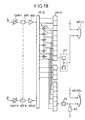
- Figure 2a shows schematically a first part of an example of an architecture according to the invention payload for a large number of channels, which connects to FIG. 2b according to the references B-B ';
- the number of channels to be conveyed is 24 in the example shown, (including 12 of each polarization XPOL, YPOL) to allow a direct comparison with the previous figure.
- the payload of FIG. 2a has, like that of the prior art, reception and emission / reception antennas, which supply radio signals received to the low noise amplification blocks LNA comprising filtering means. entrance, redundancy rings providing redundant pathways, et cetera .
- the input signals are thus channeled into channels by IMUX demultiplexing filters without filtering preset, and at the input frequency before any frequency conversion.
- the number of IMUX filters corresponds to the number of channels for the receiving antenna ANT (R), i.e. 12 for each polarization.
- the number IMUX filter for the transmit / receive antenna is of the half for each polarization, that is to say 6. Des S switches allow you to select which of the two ANT (R), ANT (T / R) antennas will be used for a channel that can be powered by both.
- Figure 2b schematically shows a second part of an example of an architecture according to the invention payload for a large number of channels, which connects to FIG. 2a according to the references B-B '.
- the signals arrive from the redundancy ring 12/16 on 16 channels, which are connected to the inputs of 16 devices frequency converters DCO1, DCO2, ... DCO16.
- these frequency conversion devices are integrated, and can be made for example by MMIC technology.
- Each frequency conversion device includes its own means to generate the transposition frequency, for example a local oscillator (LO1-6).
- Each frequency converter device includes a mixer which allows the signal to be mixed convert to frequency with signal from the local oscillator to transpose frequency.
- each conversion device frequency also includes amplification means, which can be, in a preferred embodiment, integrated with the frequency transposition means (mixer, local oscillator).
- these means amplifiers constitute the channel amplifiers which are required to provide a pre-amplified signal to power amplifiers HPA1, HPA2, ... HPA16.
- a final advantageous characteristic is proposed in Figure 2b: it involves using an oscillator local capable of generating several distinct frequencies, with a switch to choose one.
- a frequency capable of delivering a signal in a very band wide with a switch to choose which frequency of said tape will actually be used for the needs of the system.
- said configurable switches are on the application of an external command of switching. It is enough to provide the payload with the means specific to interpret and then act on commands sent from the ground, and the payload becomes reconfigurable for missions then unknown at the time of the launch of the machine.
- Figure 2b looks like the part corresponding to Figure 1b, according to a design classic. From the frequency converters, the outputs of these DOC1 DOC2, ... DCO16 converters are connected via NRFR1 noise reduction filters, NRF2, ... NRF16, arranged in series, at the inputs of respective power amplifiers HPA1, HPA2, ... HPA16. The power signals from these amplifiers power are then conveyed via a second ring of 16/12 redundancy to 18 OMUX channel filters.
- OMUX filters are powered directly from six redundancy ring outputs 12/16; the other twelve OMUX filters are supplied with from the other six outputs of the redundancy ring 12/16 via six S switches which supply six OMUX filters on the twelve.
- the signals are then routed to the ANT (T) transmitting antenna (s) or ANT transmission / reception (T / R), possibly via other bandpass filters
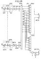
- FIG. 4 shows schematically and partially a another example of an embodiment according to the invention, in which the filtering of the channel is carried out by a filter with surface acoustic waves (SAW1, ... SAW16) arranged within frequency conversion means (DCS1, ... DCS16), comprising means for carrying out two transpositions of frequency.
- SAW1, ... SAW16 surface acoustic waves
- DCS1, ... DCS16 frequency conversion means
- the number of channels to be conveyed is 24 in the example shown, (including 12 of each polarization XPOL, YPOL) to allow a direct comparison with the previous figures.
- the payload of FIG. 4 has, like that of the prior art, reception and transmission / reception antennas, which supply radio signals received to the low noise amplification blocks LNA comprising filtering means. entrance, redundancy rings providing redundant pathways, et cetera.
- the example in Figure 4 includes a filter block of preset (F1, F2, ... F6) to cut the received signals in frequency bands of 250 MHz bandwidth.
- the thus filtered signals are then supplied to dividers power (D1, D2, ... D6) which are connected by switch arrays S at the redundancy ring 12/16.
- the input signals are thus channeled into channels by surface acoustic wave filters (SAW1, ... SAW16) which are within the conversion means of frequency, after a first frequency transposition performed using a first mixer (MS11, ... MS161) and a first local oscillator (OL11, ... OL161).
- SAW filters corresponds to the number of channels for the ANT (R) receiving antenna, i.e. 12 for each polarization, increased by the number of channels of redundancy, i.e. 4 in the example shown.
- the number of IMUX filters for the antenna transmission / reception is half for each polarization, i.e. 6, increased by the number of redundancy channels, i.e. 4 in the example shown.
- redundancy channels can be assigned indifferently to one or the other of the antennas.
- S switches select which of the two antennas ANT (R), ANT (T / R) will be used for a channel which can be powered by both.
- the signals After filtering by SAW filters, the signals are routed, within the 16 converter devices of frequency DCS1, DCS2, ... DCS16.
- Each frequency conversion device includes its own means to generate two transposition frequencies, for example two oscillators premises (OL11, OL12, ... OL161, OL162).
- Each device frequency converter according to Figure 4 includes two mixers that mix the signal to be converted in frequency with the signal from the local oscillator respective to carry out the frequency transposition.
- each device for converting frequency also includes amplification means, which can be, in a preferred embodiment, integrated with the means of a second frequency transposition (mixer, local oscillator) within each device frequency converter (DCS1, ... DCS16).
- these amplification means constitute the channel amplifiers that are needed to provide a pre-amplified signal to power amplifiers (HPA1, HPA2, ... HPA16, not shown in this figure).
- a final advantageous characteristic is proposed in figure 4: it involves using two oscillators correlated premises with frequency synthesis, capable of generating several distinct frequencies, controllable by a remote control from the ground which is applied to the entrance to command (TC1, ... TC16) provided for this purpose to choose two for the first and second transposition of frequency.
- TC1, ... TC16 entrance to command
- said frequency synthesis oscillators are configurable by the application of an external command. Just endow the payload specific means to interpret and then act on commands sent from the ground, and the payload becomes reconfigurable for missions then unknown at the time of the launch.
- Filtering operations can be performed by digital as well, provided that you first perform analog-to-digital conversion. Other treatments digital signals can be considered without going out as much of the scope of the present invention.
- FIG. 1b and 2b A comparison of Figures 1b and 2b shows significant benefits in terms of reductions in complexity, weight and size of the payload the invention compared to a conventional load design useful.
- the filters are already saved preselection. Then we also saved IMUX for channels that are not selected at level switches upstream of the first redundancy ring 12/16.
- the C2 / 3 and C3 / 2 redundancy rings of art previous are not included in the payload according to the invention. Integration of frequency converters with their local oscillators, their amplifiers gain-controlled channel, and their output preamplifiers allows increased compactness and reliability. In realization where the local oscillators are identical, with frequency selection by an associated switch, all the built-in frequency converters become identical, which simplifies their industrial manufacture.
- the performances of the whole are improved because the frequency converters work on a single channel instead of three channels contiguous.
- the parasitic mixing lines are significantly reduced if not eliminated, and equalization signal level in each channel before transposition frequency of each channel individually improves mixer performance.
Landscapes
- Engineering & Computer Science (AREA)
- Physics & Mathematics (AREA)
- Astronomy & Astrophysics (AREA)
- Aviation & Aerospace Engineering (AREA)
- General Physics & Mathematics (AREA)
- Computer Networks & Wireless Communication (AREA)
- Signal Processing (AREA)
- Radio Relay Systems (AREA)
- Input Circuits Of Receivers And Coupling Of Receivers And Audio Equipment (AREA)
- Noise Elimination (AREA)
Description
- la figure 1a, déjà mentionnée, montre schématiquement une première partie d'une architecture de conception classique d'une charge utile pour un nombre de canaux élevé, qui se raccorde à la figure 1b selon les repères A-A' ;
- la figure 1b, déjà mentionnée, montre schématiquement une deuxième partie d'une architecture de conception classique d'une charge utile pour un nombre de canaux élevé , qui se raccorde à la figure 1a selon les repères A-A';
- la figure 2a montre schématiquement une première partie d'un exemple d'une architecture selon l'invention d'une charge utile pour un nombre de canaux élevé , qui se raccorde à la figure 2b selon les repères B-B';
- la figure 2b montre schématiquement une deuxième partie d'un exemple d'une architecture selon l'invention d'une charge utile pour un nombre de canaux élevé , qui se raccorde à la figure 2a selon les repères B-B';
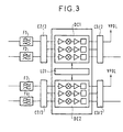
- la figure 3, déjà décrite, montre schématiquement un détail de la figure 1a, comprenant un bloc de convertisseurs de fréquence selon l'art antérieur, avec ses oscillateurs locaux associés ;
- la figure 4, qui montre schématiquement et partiellement un autre exemple d'une réalisation selon l'invention, dans laquelle le filtrage du canal est effectué par un filtre à ondes acoustiques de surface disposé au sein des moyens de conversion de fréquence, comprennant des moyens pour effectuer deux transpositions de fréquence.
Claims (19)
- Charge utile pour satellite à d canaux transparents choisi parmi c canaux, c ≥ d à l'antenne, chaque canal ayant une largeur de bande δ, ladite charge utile comprenant une partie réception alimentée par au moins une antenne de réception et une partie émission alimentant au moins une antenne d'émission, ladite charge utile comprenant en outre une première pluralité g de filtres de canal passe-bande IMUX de largeur δ qui filtrent des signaux reçus par ladite partie réception ; des moyens de transposition de fréquence, une pluralité k d'amplificateurs de canal, k ≥ d ; des moyens d'amplification de puissance, et une deuxième pluralité p de filtres de canal OMUX qui filtrent les signaux amplifiés par ladite pluralité k d'amplificateurs de canal et lesdits moyens d'amplification de puissance, lesdits k amplificateurs de canal étant couplés auxdits p filtres de canal par des moyens de redondance afin d'affecter d amplificateurs auxdits d canaux ; lesdits moyens de transposition de fréquence comprenant au moins un mélangeur et au moins une source d'un signal de fréquence de transposition, caractérisé en ce que lesdits moyens de transposition de fréquence comprennent au moins un commutateur et au moins une source de signaux fournissant q signaux de q fréquences différentes de transposition, ledit commutateur étant couplé auxdite(s) source(s) et audit mélangeur, afin de sélectionner une fréquence de transposition parmi lesdites q fréquences et la fournir audit mélangeur et en ce que ledit au moins un mélangeur est un mélangeur large bande, capable de fonctionner correctement sur toute la bande d'allocation de ladite charge utile, c'est-à-dire sur une largeur de bande ≥ dδ.
- Charge utile pour satellite à d canaux transparents selon la revendication 1, caractérisé en ce que lesdits k amplificateurs de canal à gain variable sont associés respectivement à k dispositifs de transposition de fréquence, chaque dispositif de transposition comprenant au moins un mélangeur et au moins une source d'un signal de fréquence de transposition ; les d sorties desdits d amplificateurs de canal étant couplées respectivement aux d entrées desdits dispositifs de transposition de fréquence.
- Charge utile pour satellite à d canaux transparents selon la revendication 2, caractérisé en ce que lesdits k dispositifs de transposition de fréquence comprennent au moins un premier et un deuxième mélangeurs et au moins deux sources de deux signaux de fréquence de transposition, de manière à effectuer au moins deux transpositions de fréquence pour chaque canal.
- Charge utile pour satellite à d canaux transparents selon la revendication 3, caractérisé en ce que lesdites au moins deux sources de fréquence sont des oscillateurs locaux corrélés.
- Charge utile pour satellite à d canaux transparents selon la revendication 4, caractérisé en ce que lesdits oscillateurs locaux corrélés sont des oscillateurs à synthèse de fréquence.
- Charge utile pour satellite à d canaux transparents selon la revendication 5, caractérisé en ce que lesdits oscillateurs locaux corrélés à synthèse de fréquence permettent de fournir chacun un signal à une fréquence séléctionnée parmi une pluralité c de fréquences possibles, et lesdits oscillateurs locaux corrélés à synthèse de fréquence étant commandables depuis le sol par des signaux de télécommande (TC1,...TC16), ladite charge utile comprennant en outre des moyens pour recevoir un signal de commande depuis le sol, ainsi que des moyens pour appliquer ledit signal de commande au(x)dit(s) oscillateurs locaux corrélés, lesdits au moins deux oscillateurs locaux corrélés à synthèse de fréquence étant couplé(s) auxdite(s) source(s) et auxdits mélangeurs, afin de sélectionner une premiere et une deuxième fréquences de transposition parmi lesdites c fréquences et les fournir auxdits mélangeurs.
- Charge utile pour satellite à d canaux transparents selon l'une quelconque des revendications 3 à 6, caractérisé en ce que un filtre à ondes acoustiques de surface (SAW1,... SAW16) est disposé entre lesdits au moins deux mélangeurs et avant ledit amplificateur de canal à gain variable, de manière à effectuer le filtrage de canal par lesdits filtres SAW avant ladite deuxième mélangeur.
- Charge utile pour satellite de télécommunications pouvant véhiculer un grand nombre d de canaux transparents, ladite charge utile étant apte à recevoir des signaux montants constitués par des ondes radioélectriques dans une première bande de fréquences ayant une première fréquence centrale et une première largeur de bande, et d'émettre des signaux descendants constitués par des ondes radioélectriques dans une deuxième bande de fréquences ayant une deuxième fréquence centrale et une deuxième largeur de bande, ladite deuxième fréquence centrale étant différente de ladite première fréquence centrale ;ladite charge utile comportant :au moins une antenne radioélectrique, ladite au moins une antenne étant apte à recevoir et/ou à émettre des ondes radioélectriques ;une pluralité e de filtres d'entrée,une pluralité f d'amplificateurs faible bruit,une pluralité g de filtres IMUX de démultiplexage,une pluralité h de convertisseurs de fréquences,une pluralité j d'oscillateurs locaux,une pluralité k d'amplificateurs de canal,une pluralité m de filtres de réduction de bruit,une pluralité n d'amplificateurs de puissance,une pluralité p de filtres OMUX, etdes moyens de couplage et d'acheminement des signaux ;les différents éléments énumérés ci-dessus étant disposés et raccordés par lesdits moyens de couplage et d'acheminement des signaux, de manière à effectuer un filtrage de canal sur lesdits signaux par lesdits g filtres IMUX avant d'effectuer une première transposition de fréquence desdits signaux moyennant lesdits h convertisseurs de fréquence, le nombre h de convertisseurs de fréquence étant au moins égal au nombre d de canaux : h ≥ d, caractérisé en ce que lesdits convertisseurs de fréquence comprennent au moins un commutateur et au moins une source de signaux fournissant q signaux de q fréquences différentes de transposition, ledit commutateur étant couplé auxdite(s) source(s) et audit mélangeur, afin de sélectionner une fréquence de transposition parmi lesdites q fréquences et la fournir audit convertisseur, et caractérisé en ce que lesdits convertisseurs de fréquence sont des convertisseurs large bande, pouvant convertir en fréquence n'importe quel canal, depuis n'importe quelle fréquence de canal dans ladite première bande de fréquences vers n'importe quelle fréquence de canal dans ladite deuxième bande de fréquences, moyennant l'application audit convertisseur d'une fréquence de transposition appropriée fournie par un desdits oscillateurs locaux sur commande appliquée audit commutateur associé audit oscillateur local.
- Charge utile pour satellite de télécommunications pouvant véhiculer un grand nombre d de canaux transparents, selon l'une quelconque des revendications 1 à 2, 7 ou 8, caractérisé en ce que chaque oscillateur local peut fournir une pluralité q de fréquences de transposition, dont une peut être sélectionnée à l'aide d'un commutateur associé audit chaque oscillateur local, ledit commutateur étant configurable sur commande.
- Charge utile pour satellite à d canaux transparents selon l'une quelconque des revendications 1 à 2, 7 à 9, caractérisé en ce que ladite charge utile comprend en outre des moyens pour recevoir un signal de commande depuis le sol, ainsi que des moyens pour appliquer ledit signal de commande au(x) dit(s) commutateur(s) afin de commander la configuration de ce(s) dernier(s).
- Charge utile pour satellite à d canaux transparents selon l'une quelconque des revendications 1 à 10, caractérisé en ce que lesdits k amplificateurs de canal sont physiquement associés auxdits h convertisseurs de fréquence, et h = k.
- Charge utile pour satellite à d canaux transparents selon la revendication 11, caractérisé en ce que lesdits k amplificateurs et lesdits h = k convertisseurs de fréquence sont réalisés en MMIC et sont intégrés au sein d'un dispositif amplificateur de canal / convertisseur de fréquence.
- Charge utile pour satellite à d canaux transparents selon l'une quelconque des revendications 1 à 12, caractérisé en ce que lesdits k amplificateurs de canal sont des amplificateurs à gain contrôlable.
- Charge utile pour satellite à d canaux transparents selon la revendication 13, caractérisé en ce que lesdits k amplificateurs à gain contrôlable sont disposés et raccordés par lesdits moyens de couplage et d'acheminement des signaux, aux entrées desdits h convertisseurs de fréquence de manière à effectuer l'amplification de canal avant d'effectuer ladite première transposition de fréquence.
- Charge utile pour satellite à d canaux transparents selon l'une quelconque des revendications 1 à 16, caractérisé en ce que ladite charge utile comporte en outre des moyens de traitement numérique de signal, comprenant notamment une pluralité r de convertisseurs analogique numérique, des moyens de filtrage numérique, et une pluralité r de convertisseurs numérique analogique.
- Charge utile pour satellite à d canaux transparents selon la revendication 15, caractérisé en ce que lesdits moyens de traitement numérique sont disposés et raccordés par lesdits moyens de couplage et d'acheminement de signal de manière à effectuer ledit traitement numérique après ladite première transposition de fréquence.
- Charge utile pour satellite à d canaux transparents selon l'une quelconque des revendications 1 à 16, caractérisé en ce que lesdits moyens de traitement numérique comprennent en outre des moyens de transposition en fréquence aptes à effectuer une deuxième transposition de fréquence avant la conversion numérique analogique par ladite pluralité r de convertisseurs numérique analogique.
- Charge utile pour satellite à d canaux transparents selon l'une quelconque des revendications 1 à 17, caractérisé en ce que lesdits j oscillateurs locaux sont des oscillateurs à synthèse de fréquence.
- Charge utile pour satellite à d canaux transparents selon l'une quelconque des revendications 1 à 18, caractérisé en ce que les différents éléments sont mécaniquement intégrés par canal, chaque canal comportant au moins un linéariseur, un convertisseur de fréquence, un amplificateur de canal, et un amplificateur de puissance ainsi que l'alimentation de puissance électrique conditionnée nécessaire au bon fonctionnement de l'ensemble.
Applications Claiming Priority (2)
| Application Number | Priority Date | Filing Date | Title |
|---|---|---|---|
| FR9414100 | 1994-11-24 | ||
| FR9414100A FR2727590B1 (fr) | 1994-11-24 | 1994-11-24 | Charge utile de satellite a canaux transparents integres |
Publications (2)
| Publication Number | Publication Date |
|---|---|
| EP0714179A1 EP0714179A1 (fr) | 1996-05-29 |
| EP0714179B1 true EP0714179B1 (fr) | 1999-06-23 |
Family
ID=9469119
Family Applications (1)
| Application Number | Title | Priority Date | Filing Date |
|---|---|---|---|
| EP95402637A Expired - Lifetime EP0714179B1 (fr) | 1994-11-24 | 1995-11-22 | Charge utile de satellite à canaux transparents intégrés |
Country Status (6)
| Country | Link |
|---|---|
| US (1) | US5963845A (fr) |
| EP (1) | EP0714179B1 (fr) |
| JP (1) | JP3192361B2 (fr) |
| CA (1) | CA2163406C (fr) |
| DE (1) | DE69510431T2 (fr) |
| FR (1) | FR2727590B1 (fr) |
Families Citing this family (40)
| Publication number | Priority date | Publication date | Assignee | Title |
|---|---|---|---|---|
| US5956620A (en) * | 1997-01-17 | 1999-09-21 | Com Dev Limited | Analog processor for digital satellites |
| US6047162A (en) * | 1997-09-25 | 2000-04-04 | Com Dev Limited | Regional programming in a direct broadcast satellite |
| US6657978B1 (en) * | 1998-04-23 | 2003-12-02 | Transworld Communications (Usa), Inc. | Optimized integrated high capacity digital satellite trunking network |
| US6301465B1 (en) * | 1998-10-12 | 2001-10-09 | Trw Inc. | Adaptive transceiver architecture for real time allocation of communications resources in a satellite based telecommunication system |
| US6438354B2 (en) * | 1998-12-23 | 2002-08-20 | Hughes Electronics Corporation | Reconfigurable satellite and antenna coverage communications backup capabilities |
| US7327698B1 (en) * | 1999-06-03 | 2008-02-05 | The Directv Group, Inc. | Method and system for providing satellite communications using on-orbit payload configuration and reconfiguration |
| US7327775B1 (en) * | 1999-12-23 | 2008-02-05 | Nokia Corporation | CDMA receiver |
| US6665518B1 (en) * | 2000-03-01 | 2003-12-16 | Northrop Gumman Corporation | Asymmetric assignment of space-borne communication system resources |
| US7583728B2 (en) | 2002-10-25 | 2009-09-01 | The Directv Group, Inc. | Equalizers for layered modulated and other signals |
| US7184489B2 (en) | 2001-04-27 | 2007-02-27 | The Directv Group, Inc. | Optimization technique for layered modulation |
| US8005035B2 (en) | 2001-04-27 | 2011-08-23 | The Directv Group, Inc. | Online output multiplexer filter measurement |
| US7639759B2 (en) | 2001-04-27 | 2009-12-29 | The Directv Group, Inc. | Carrier to noise ratio estimations from a received signal |
| US7151807B2 (en) * | 2001-04-27 | 2006-12-19 | The Directv Group, Inc. | Fast acquisition of timing and carrier frequency from received signal |
| US7209524B2 (en) * | 2001-04-27 | 2007-04-24 | The Directv Group, Inc. | Layered modulation for digital signals |
| US7512189B2 (en) | 2001-04-27 | 2009-03-31 | The Directv Group, Inc. | Lower complexity layered modulation signal processor |
| US7471735B2 (en) | 2001-04-27 | 2008-12-30 | The Directv Group, Inc. | Maximizing power and spectral efficiencies for layered and conventional modulations |
| US7483505B2 (en) | 2001-04-27 | 2009-01-27 | The Directv Group, Inc. | Unblind equalizer architecture for digital communication systems |
| US7173981B1 (en) | 2001-04-27 | 2007-02-06 | The Directv Group, Inc. | Dual layer signal processing in a layered modulation digital signal system |
| US7822154B2 (en) | 2001-04-27 | 2010-10-26 | The Directv Group, Inc. | Signal, interference and noise power measurement |
| US7245671B1 (en) | 2001-04-27 | 2007-07-17 | The Directv Group, Inc. | Preprocessing signal layers in a layered modulation digital signal system to use legacy receivers |
| US7423987B2 (en) | 2001-04-27 | 2008-09-09 | The Directv Group, Inc. | Feeder link configurations to support layered modulation for digital signals |
| US7184473B2 (en) * | 2001-04-27 | 2007-02-27 | The Directv Group, Inc. | Equalizers for layered modulated and other signals |
| US7502430B2 (en) | 2001-04-27 | 2009-03-10 | The Directv Group, Inc. | Coherent averaging for measuring traveling wave tube amplifier nonlinearity |
| WO2004004193A2 (fr) | 2002-07-01 | 2004-01-08 | The Directv Group, Inc. | Amelioration de la performance d'un signal 8psk hierarchise |
| ES2604453T3 (es) | 2002-07-03 | 2017-03-07 | The Directv Group, Inc. | Método y aparato para modulación en capas |
| US7463676B2 (en) | 2002-10-25 | 2008-12-09 | The Directv Group, Inc. | On-line phase noise measurement for layered modulation |
| US7474710B2 (en) | 2002-10-25 | 2009-01-06 | The Directv Group, Inc. | Amplitude and phase matching for layered modulation reception |
| US7529312B2 (en) | 2002-10-25 | 2009-05-05 | The Directv Group, Inc. | Layered modulation for terrestrial ATSC applications |
| AU2003282854A1 (en) | 2002-10-25 | 2004-05-25 | The Directv Group, Inc. | Method and apparatus for tailoring carrier power requirements according to availability in layered modulation systems |
| US7230480B2 (en) | 2002-10-25 | 2007-06-12 | The Directv Group, Inc. | Estimating the operating point on a non-linear traveling wave tube amplifier |
| US20040196798A1 (en) * | 2003-04-01 | 2004-10-07 | Abousleman Glen P | System and method for wireless transmission of signals using multiple channels assigned in response to signal type |
| US7502429B2 (en) | 2003-10-10 | 2009-03-10 | The Directv Group, Inc. | Equalization for traveling wave tube amplifier nonlinearity measurements |
| WO2008125876A1 (fr) | 2007-04-16 | 2008-10-23 | Astrium Limited | Acheminement des canaux de liaison descendante dans un satellite de communication |
| FR2968501B1 (fr) * | 2010-12-02 | 2013-04-26 | Astrium Sas | Reseau de commutateurs et charge utile de satellite de telecommunications comportant un reseau de commutateurs |
| US8699982B2 (en) * | 2012-03-27 | 2014-04-15 | Adc Telecommunications, Inc. | Systems and methods for implementing a distributed antenna system in a radio frequency integrated circuit |
| US9596120B2 (en) * | 2013-09-26 | 2017-03-14 | Nec Corporation | Signal transmission apparatus, distortion compensation apparatus, and signal transmission method |
| US9960836B2 (en) | 2014-05-19 | 2018-05-01 | L-3 Technologies, Inc. | Method and system for satellite using multifunctional motherboard |
| FR3055493B1 (fr) * | 2016-08-23 | 2018-09-21 | Thales Sa | Dispositif de conversion de frequences a double oscillateur local et charge utile de satellite comprenant un tel dispositif |
| US10674376B2 (en) * | 2018-01-26 | 2020-06-02 | Lockheed Martin Corporation | Disruptive flexible GEO satellite constellation system |
| DE102020110652B4 (de) | 2020-04-20 | 2022-06-15 | Tesat-Spacecom Gmbh & Co. Kg | Verstärker mit Leistungskombination und interner Redundanz |
Family Cites Families (9)
| Publication number | Priority date | Publication date | Assignee | Title |
|---|---|---|---|---|
| US3810255A (en) * | 1971-06-10 | 1974-05-07 | Communications Satellite Corp | Frequency translation routing communications transponder |
| US4002980A (en) * | 1971-08-04 | 1977-01-11 | Siemens Aktiengesellschaft | Relay station in a telecommunications transmission system |
| US4941200A (en) * | 1987-08-03 | 1990-07-10 | Orion Industries, Inc. | Booster |
| US5287543A (en) * | 1991-10-07 | 1994-02-15 | General Electric Co. | Multichannel communication system with an amplifier in each channel |
| US5317595A (en) * | 1992-06-30 | 1994-05-31 | Nokia Mobile Phones Ltd. | Rapidly adaptable channel equalizer |
| US5594939A (en) * | 1992-11-23 | 1997-01-14 | Hughes Aircraft Company | Synthesizer routing architecture for a switching apparatus |
| JPH06224644A (ja) * | 1993-01-25 | 1994-08-12 | Nec Corp | 半導体装置 |
| US5517685A (en) * | 1993-04-27 | 1996-05-14 | Matsushita Electric Industrial Co., Ltd. | PLL circuit having a multiloop, and FM receiving method and apparatus able to utilize the same |
| US5613197A (en) * | 1994-11-03 | 1997-03-18 | Hughes Aircraft Co. | Multi-channel transponder with channel amplification at a common lower frequency |
-
1994
- 1994-11-24 FR FR9414100A patent/FR2727590B1/fr not_active Expired - Fee Related
-
1995
- 1995-11-21 CA CA002163406A patent/CA2163406C/fr not_active Expired - Fee Related
- 1995-11-21 US US08/561,247 patent/US5963845A/en not_active Expired - Fee Related
- 1995-11-22 DE DE69510431T patent/DE69510431T2/de not_active Expired - Lifetime
- 1995-11-22 EP EP95402637A patent/EP0714179B1/fr not_active Expired - Lifetime
- 1995-11-24 JP JP30625595A patent/JP3192361B2/ja not_active Expired - Fee Related
Also Published As
| Publication number | Publication date |
|---|---|
| DE69510431D1 (de) | 1999-07-29 |
| JPH08223099A (ja) | 1996-08-30 |
| EP0714179A1 (fr) | 1996-05-29 |
| FR2727590A1 (fr) | 1996-05-31 |
| DE69510431T2 (de) | 1999-12-16 |
| US5963845A (en) | 1999-10-05 |
| FR2727590B1 (fr) | 1996-12-27 |
| JP3192361B2 (ja) | 2001-07-23 |
| CA2163406C (fr) | 2001-01-09 |
| CA2163406A1 (fr) | 1996-05-25 |
Similar Documents
| Publication | Publication Date | Title |
|---|---|---|
| CA2163406C (fr) | Charge utile de satellite a canaux transparents integres | |
| EP0584012B1 (fr) | Dispositif de commutation transparente, notamment pour le domaine spatial et charge utile utilisant un tel dispositif | |
| EP2723002B1 (fr) | Système de télécommunication par satellite permettant d'assurer un trafic en étoile et un trafic maillé | |
| EP1014598B1 (fr) | Satellite reconfigurable ayant une couverture d'antenne modifiable et des possibilités de sauvegarde de communications | |
| EP0734093B1 (fr) | Dispositif d'alimentation d'une antenne multisources et multifaisceaux | |
| EP3002825B1 (fr) | Antenne à réflecteur(s) conformé(s) reconfigurable en orbite | |
| EP2337238B1 (fr) | Système d'émission et de réception multi-spots à bord d'un satellite | |
| CA2157209A1 (fr) | Repeteurs pour satellites multifaisceau | |
| EP2050207B1 (fr) | Dispositif d'amplification large bande | |
| FR2811480A1 (fr) | Antenne de telecommunication destinee a couvrir une large zone terrestre | |
| EP2104243B1 (fr) | Réseau de télécommunication | |
| EP2055633B1 (fr) | Procédé d'optimisation de la charge utile d'un satellite de télécommunication multifaisceaux | |
| EP2481171A1 (fr) | Charge utile pour satellite multifaisceaux | |
| EP0118357B1 (fr) | Système d'antenne électronique pour réseau cellulaire de radiotéléphones associant des stations fixes à des postes mobiles et à des postes portatifs | |
| EP1499013B1 (fr) | Dispositif d'amplification pour satellite | |
| EP2876814B1 (fr) | Dispositif d'émission et de réception par satellite à fort taux d'atténuation des multi-trajets, répéteur et satellite équipés d'un tel dispositif | |
| US20190103912A1 (en) | Adaptive satellite channelizer | |
| EP3424156B1 (fr) | Procede de telecommunication dans un systeme a couverture geographique multi-spots, station terrestre et dispositif relais correspondants | |
| FR2864385A1 (fr) | Dispositif de brassage spatio-frequentiel de signaux pour repeteur de telecommunications d'un satellite, repeteur et satellite associes | |
| FR2950496A1 (fr) | Charge utile pour satellite multifaisceaux | |
| FR2969431A1 (fr) | Satellite de diffusion a couverture multifaisceaux et plan de frequence flexible |
Legal Events
| Date | Code | Title | Description |
|---|---|---|---|
| PUAI | Public reference made under article 153(3) epc to a published international application that has entered the european phase |
Free format text: ORIGINAL CODE: 0009012 |
|
| AK | Designated contracting states |
Kind code of ref document: A1 Designated state(s): DE GB IT SE |
|
| 17P | Request for examination filed |
Effective date: 19960521 |
|
| 17Q | First examination report despatched |
Effective date: 19961004 |
|
| GRAG | Despatch of communication of intention to grant |
Free format text: ORIGINAL CODE: EPIDOS AGRA |
|
| GRAG | Despatch of communication of intention to grant |
Free format text: ORIGINAL CODE: EPIDOS AGRA |
|
| GRAH | Despatch of communication of intention to grant a patent |
Free format text: ORIGINAL CODE: EPIDOS IGRA |
|
| GRAH | Despatch of communication of intention to grant a patent |
Free format text: ORIGINAL CODE: EPIDOS IGRA |
|
| RAP1 | Party data changed (applicant data changed or rights of an application transferred) |
Owner name: ALCATEL SPACE INDUSTRIES |
|
| GRAA | (expected) grant |
Free format text: ORIGINAL CODE: 0009210 |
|
| RAP1 | Party data changed (applicant data changed or rights of an application transferred) |
Owner name: ALCATEL |
|
| AK | Designated contracting states |
Kind code of ref document: B1 Designated state(s): DE GB IT SE |
|
| GBT | Gb: translation of ep patent filed (gb section 77(6)(a)/1977) |
Effective date: 19990623 |
|
| REF | Corresponds to: |
Ref document number: 69510431 Country of ref document: DE Date of ref document: 19990729 |
|
| PLBE | No opposition filed within time limit |
Free format text: ORIGINAL CODE: 0009261 |
|
| STAA | Information on the status of an ep patent application or granted ep patent |
Free format text: STATUS: NO OPPOSITION FILED WITHIN TIME LIMIT |
|
| 26N | No opposition filed | ||
| PGFP | Annual fee paid to national office [announced via postgrant information from national office to epo] |
Ref country code: SE Payment date: 20011105 Year of fee payment: 7 |
|
| REG | Reference to a national code |
Ref country code: GB Ref legal event code: IF02 |
|
| PG25 | Lapsed in a contracting state [announced via postgrant information from national office to epo] |
Ref country code: SE Free format text: LAPSE BECAUSE OF NON-PAYMENT OF DUE FEES Effective date: 20021123 |
|
| EUG | Se: european patent has lapsed | ||
| PGFP | Annual fee paid to national office [announced via postgrant information from national office to epo] |
Ref country code: IT Payment date: 20061130 Year of fee payment: 12 |
|
| PG25 | Lapsed in a contracting state [announced via postgrant information from national office to epo] |
Ref country code: IT Free format text: LAPSE BECAUSE OF NON-PAYMENT OF DUE FEES Effective date: 20071122 |
|
| REG | Reference to a national code |
Ref country code: GB Ref legal event code: 732E Free format text: REGISTERED BETWEEN 20090910 AND 20090916 |
|
| PGFP | Annual fee paid to national office [announced via postgrant information from national office to epo] |
Ref country code: DE Payment date: 20111130 Year of fee payment: 17 |
|
| PGFP | Annual fee paid to national office [announced via postgrant information from national office to epo] |
Ref country code: GB Payment date: 20121025 Year of fee payment: 18 |
|
| REG | Reference to a national code |
Ref country code: DE Ref legal event code: R119 Ref document number: 69510431 Country of ref document: DE Effective date: 20130601 |
|
| PG25 | Lapsed in a contracting state [announced via postgrant information from national office to epo] |
Ref country code: DE Free format text: LAPSE BECAUSE OF NON-PAYMENT OF DUE FEES Effective date: 20130601 |
|
| GBPC | Gb: european patent ceased through non-payment of renewal fee |
Effective date: 20131122 |
|
| PG25 | Lapsed in a contracting state [announced via postgrant information from national office to epo] |
Ref country code: GB Free format text: LAPSE BECAUSE OF NON-PAYMENT OF DUE FEES Effective date: 20131122 |