EP0713833B1 - Multi-compartmentalized dumping body with movable floor - Google Patents
Multi-compartmentalized dumping body with movable floor Download PDFInfo
- Publication number
- EP0713833B1 EP0713833B1 EP95460041A EP95460041A EP0713833B1 EP 0713833 B1 EP0713833 B1 EP 0713833B1 EP 95460041 A EP95460041 A EP 95460041A EP 95460041 A EP95460041 A EP 95460041A EP 0713833 B1 EP0713833 B1 EP 0713833B1
- Authority
- EP
- European Patent Office
- Prior art keywords
- walls
- edge portion
- floor
- storage body
- partition
- Prior art date
- Legal status (The legal status is an assumption and is not a legal conclusion. Google has not performed a legal analysis and makes no representation as to the accuracy of the status listed.)
- Expired - Lifetime
Links
- 238000003860 storage Methods 0.000 claims description 168
- 238000005192 partition Methods 0.000 claims description 31
- 238000005056 compaction Methods 0.000 claims description 9
- 238000000638 solvent extraction Methods 0.000 claims description 4
- 230000008878 coupling Effects 0.000 claims 22
- 238000010168 coupling process Methods 0.000 claims 22
- 238000005859 coupling reaction Methods 0.000 claims 22
- 239000002131 composite material Substances 0.000 claims 2
- 238000007599 discharging Methods 0.000 claims 2
- 230000000712 assembly Effects 0.000 description 30
- 238000000429 assembly Methods 0.000 description 30
- 239000000463 material Substances 0.000 description 30
- 230000007246 mechanism Effects 0.000 description 19
- 239000002699 waste material Substances 0.000 description 16
- 229910000831 Steel Inorganic materials 0.000 description 7
- 230000005484 gravity Effects 0.000 description 7
- 239000010959 steel Substances 0.000 description 7
- 229920003023 plastic Polymers 0.000 description 5
- 239000004033 plastic Substances 0.000 description 5
- 239000011521 glass Substances 0.000 description 3
- 238000004064 recycling Methods 0.000 description 3
- 239000000123 paper Substances 0.000 description 2
- 238000005204 segregation Methods 0.000 description 2
- 238000000926 separation method Methods 0.000 description 2
- 230000032258 transport Effects 0.000 description 2
- 229910052782 aluminium Inorganic materials 0.000 description 1
- XAGFODPZIPBFFR-UHFFFAOYSA-N aluminium Chemical compound [Al] XAGFODPZIPBFFR-UHFFFAOYSA-N 0.000 description 1
- 238000013459 approach Methods 0.000 description 1
- 230000005465 channeling Effects 0.000 description 1
- 230000003247 decreasing effect Effects 0.000 description 1
- 239000012530 fluid Substances 0.000 description 1
- 238000004519 manufacturing process Methods 0.000 description 1
- 229910052751 metal Inorganic materials 0.000 description 1
- 239000002184 metal Substances 0.000 description 1
- 238000000034 method Methods 0.000 description 1
- 238000003825 pressing Methods 0.000 description 1
Images





Classifications
-
- B—PERFORMING OPERATIONS; TRANSPORTING
- B65—CONVEYING; PACKING; STORING; HANDLING THIN OR FILAMENTARY MATERIAL
- B65F—GATHERING OR REMOVAL OF DOMESTIC OR LIKE REFUSE
- B65F3/00—Vehicles particularly adapted for collecting refuse
- B65F3/24—Vehicles particularly adapted for collecting refuse with devices for unloading the tank of a refuse vehicle
-
- B—PERFORMING OPERATIONS; TRANSPORTING
- B65—CONVEYING; PACKING; STORING; HANDLING THIN OR FILAMENTARY MATERIAL
- B65F—GATHERING OR REMOVAL OF DOMESTIC OR LIKE REFUSE
- B65F1/00—Refuse receptacles; Accessories therefor
- B65F1/0033—Refuse receptacles; Accessories therefor specially adapted for segregated refuse collecting, e.g. receptacles with several compartments; Combination of receptacles
- B65F1/004—Refuse receptacles; Accessories therefor specially adapted for segregated refuse collecting, e.g. receptacles with several compartments; Combination of receptacles the receptacles being divided in compartments by partitions
-
- B—PERFORMING OPERATIONS; TRANSPORTING
- B65—CONVEYING; PACKING; STORING; HANDLING THIN OR FILAMENTARY MATERIAL
- B65F—GATHERING OR REMOVAL OF DOMESTIC OR LIKE REFUSE
- B65F3/00—Vehicles particularly adapted for collecting refuse
- B65F3/001—Vehicles particularly adapted for collecting refuse for segregated refuse collecting, e.g. vehicles with several compartments
-
- B—PERFORMING OPERATIONS; TRANSPORTING
- B65—CONVEYING; PACKING; STORING; HANDLING THIN OR FILAMENTARY MATERIAL
- B65F—GATHERING OR REMOVAL OF DOMESTIC OR LIKE REFUSE
- B65F3/00—Vehicles particularly adapted for collecting refuse
- B65F3/14—Vehicles particularly adapted for collecting refuse with devices for charging, distributing or compressing refuse in the interior of the tank of a refuse vehicle
- B65F3/20—Vehicles particularly adapted for collecting refuse with devices for charging, distributing or compressing refuse in the interior of the tank of a refuse vehicle with charging pistons, plates, or the like
- B65F3/201—Vehicles particularly adapted for collecting refuse with devices for charging, distributing or compressing refuse in the interior of the tank of a refuse vehicle with charging pistons, plates, or the like the charging pistons, plates or the like moving rectilinearly
-
- B—PERFORMING OPERATIONS; TRANSPORTING
- B65—CONVEYING; PACKING; STORING; HANDLING THIN OR FILAMENTARY MATERIAL
- B65F—GATHERING OR REMOVAL OF DOMESTIC OR LIKE REFUSE
- B65F3/00—Vehicles particularly adapted for collecting refuse
- B65F3/24—Vehicles particularly adapted for collecting refuse with devices for unloading the tank of a refuse vehicle
- B65F3/26—Vehicles particularly adapted for collecting refuse with devices for unloading the tank of a refuse vehicle by tipping the tank
-
- B—PERFORMING OPERATIONS; TRANSPORTING
- B65—CONVEYING; PACKING; STORING; HANDLING THIN OR FILAMENTARY MATERIAL
- B65F—GATHERING OR REMOVAL OF DOMESTIC OR LIKE REFUSE
- B65F3/00—Vehicles particularly adapted for collecting refuse
- B65F3/02—Vehicles particularly adapted for collecting refuse with means for discharging refuse receptacles thereinto
- B65F2003/0263—Constructional features relating to discharging means
- B65F2003/0279—Constructional features relating to discharging means the discharging means mounted at the front of the vehicle
Definitions
- the present invention relates to refuse vehicles for collecting and transporting garbage and recyclable materials from residences or other commercial establishments to a central disposal point such as a dump, incinerator, or recycling facility. More specifically, the present invention relates to a multiple compartment storage body having an upper compartment and a lower compartment separated by a vertically movable partition according to the preamble of claim 1.
- Waste collecting and hauling devices and vehicles typically include a single volume or compartment in which all collected materials are stored and transported. As a result, the collected materials are co-mingled with one another in one large single compartment which is unloaded at a central disposal site.
- recyclable commodities are preferably segregated and contained within different compartments.
- different compartments For example, depending upon local recycling facilities, it is often acceptable to co-mingle glass, plastic and aluminum recyclable commodities with each other. However, these three commodities must be segregated from paper and newsprint.
- special vehicles having multiple compartments are required for collecting recyclable commodities. Because the amount of each commodity may vary from day to day or from site to site, it is also advantageous to provide compartments which have adjustable volumes to provide variable capacities for containing the commodities. Although the multiple compartments allow different commodities to be separated, compartmentalization also reduces the storage volume of the storage body. In addition, because of the increased number of walls and corners within the individual compartments, less material may be compacted and contained within the interior volume of the storage body.
- refuse vehicles typically include rams or compactors for further compacting the refuse within the individual compartments.
- the need for further compacting the refuse material also increases. Compaction of the refuse materials permits larger amounts of refuse material to be contained within the storage body, thereby reducing the number of trips and the total cost associated with collecting the refuse.
- compaction of the refuse material within the storage body also makes unloading the refuse from the vehicle more difficult. As a result, compacted refuse within the storage body must be loosened and uncompacted so that the material may be dumped or pushed from the storage body. Loosening the compacted refuse or recyclable material requires additional time and tools and increases the cost of operating the refuse collection vehicle.
- Unloading the compacted refuse from the storage body is further complicated in storage bodies having hopper discharge openings which narrow towards the opening. Because these discharge openings are generally funnel shaped, compacted refuse material within the storage body actually becomes more compacted as the material approaches the opening. As a result, storage bodies utilizing hopper-shaped discharge openings as part of the floor of the storage body are especially difficult to unload.
- EPO 0 654 424 A was published on May 24, 1995 but has a priority date of November 18, 1993 in the contracting countries of Belgium, Germany and Italy. Accordingly, EPO 0 654 424 A is relevant (as regards novelty - art 54 (3) EPC) only for the countries of Belgium, Germany and Italy.
- EPO 0 654 424 A discloses a modular assembly for selective collection and transport of waste.
- EPO 0 654 414 A discloses a mobile plate 2 which is selectively raised and lowered to compact waste within an upper compartment and lower compartment.
- Reference DE 29 14 532A discloses a storage body having a separating wall 25 which pivots about an axis 23 adjacent to floor of the storage body. Loading and unloading of refuse is inflexible and is more difficult to complete.
- the present invention is an improved multiple compartment storage body for a refuse collection vehicle, as disclosed in claim 1.
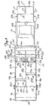
- FIG. 1 is a side elevational view of a refuse collection vehicle, with portions shown in section.
- FIG. 2 is a top view of the refuse collection vehicle of FIG. 1, with portions shown in section.
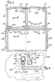
- FIG. 3 is a sectional view as taken along lines 3--3 of FIG. 1.
- FIG. 4 is an enlarged fragmentary sectional view as taken along lines 4--4 of FIG. 3.
- FIG. 5 is a fragmentary side elevational view of a portion of the storage body of the refuse collection vehicle of FIG. 1, showing a locking/release mechanism.
- FIG. 6 is a sectional view of a portion of the storage body of FIG. 1 illustrating adjustable positioning of bulkheads within the storage body.
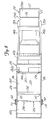
- FIG. 7 is a side elevational view of an alternate embodiment of the inventive refuse collection vehicle, with portions shown in section.
- FIG. 8 is a top view of the refuse collection vehicle of FIG. 7, with portions shown in section.
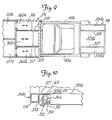
- FIG. 9 is a schematic illustration of an alternate embodiment of the inventive storage body.
- FIG. 10 is a schematic illustration of an alternate embodiment of the inventive storage body.
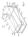
- FIG. 11 is a schematic illustration of an alternate embodiment of the inventive storage body.
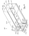
- FIG. 12 is a schematic illustration of an alternate embodiment of the inventive storage body.
- refuse collection vehicle 10 generally includes chassis 12, loading trough or bin 14, lifting apparatus 15, compactor 16 and storage body 18.
- Chassis 12 may have a variety of configurations depending upon the configurations of loading bin 14, compactor 16 and the storage body 18 being used.
- Chassis 12 supports and transports compactor 16 and storage body 18 between material pick up and disposal sites. Chassis 12 further lifts and tips storage body 18 to unload refuse from storage body 18 and includes cab 20, frame 22, lifting jack 23 and wheels 24.
- Cab 20 is positioned forward of compactor 16 and storage body 18.
- Cab 20 houses an engine, drive train and vehicle controls of vehicle 10.
- Frame 22 extends rearwardly from cab 20 and provides a base for supporting compactor 16 and storage body 18.
- frame 22 is pivotally coupled to compactor 16 and storage body 18 at pivot 25.
- Lifting jack 23 preferably is a hydraulic piston-cylinder assembly as is conventionally used for tipping or lifting storage bodies in grain and refuse vehicles.
- Lifting jack 23 is mounted between frame 22 and compactor 16 in storage body 18 towards a front end of chassis 12.
- Lifting jack 23 lifts and tips compactor 16 and storage body 18 near a front end of chassis 12 about pivot 25 so that refuse may be unloaded from a rear end of storage body 18.
- lifting jack 23 may be mounted between frame 22 and a side of either compactor 16 or storage body 18 for tipping the storage body 18 to one side to discharge refuse out a side discharge opening.
- lifting jack 23 may alternatively employ pneumatic or other means for tipping compactor 16 and storage body 18.
- Wheels 24 are rotatably mounted to cab 20 and frame 22 to support cab 20 and frame 22 above the surface.
- Loading bin 14 is a generally rectangular cart or dumpster including a bottom floor 26, a plurality of exterior side walls 27, interior dividing walls 28,29, rollers 30 and lifting lugs 32a (as shown in FIG. 2) and 32b.
- Floor 26 and exterior walls 27 define a storage capacity or volume for loading bin 14.
- Dividing wall 28 extends between floor 26 and exterior walls 27 to divide the storage volume of loading bin 14 into a front half and a back half.
- Dividing wall 29 extends from dividing wall 28 to the forward end of exterior walls 27 to divide the remaining front half of loading bin 14 into two side-by-side compartments.
- dividing walls 28 and 29 in conjunction with floor 26 and exterior wall 27 define three distinct compartments, front right compartment 34a, front left compartment 34b (shown in FIG.
- Each compartment 34 is sized and designed for the reception of garbage and recyclable materials which must be separated.
- rear compartment 34c extends along an entire rear half of loading bin 14 for reception of generally non-recyclable garbage.
- Front right compartment 34a and front left compartment 34b divide the remaining front half of loading bin 14 for the reception of paper and glass or plastic material, respectively.
- Rollers 30 extend downward from floor 26 of bin 14 and support bin 14 above the surface. Rollers 30 permit bin 14 to be detached from vehicle 10 for movement to otherwise inexcessible loading and fill stations.
- Lifting lugs 32a, 32b are preferably cylindrical or tubular shaped and sized for receiving an engaging member of lifting apparatus 15.
- Lifting lugs 32a, 32b are mounted beside portions of exterior walls 27. Preferably, lifting lugs 32a, 32b are located towards a rear portion of loading bin 14. Lifting lugs 32a, 32b permit loading pin 14 to be releasably engaged by lifting apparatus 15 so that loading bin 14 may be lifted above compactor 16 and unloaded into compactor 16 as shown by phantom lines 36.
- loading bin 14 may comprise side-loading bins secured to one or both sides of compactor 16 wherein the compartments are preferably lifted along and adjacent to sides of compactor 16 until above compactor 16 where bin 14 is tipped to dispense the materials from the compartments into compactor 16. As can be appreciated, bin 14 may alternatively be fixedly attached to lifting apparatus 15.
- Lifting apparatus 15 lifts the contents of loading bin 14 above compactor 16 to unload the contents of loading bin 14 into compactor 16 as shown by phantom lines 36.
- lifting apparatus 15 preferably includes a pair of lifting arms or forks 40a and 40b which pivotally extend in front of cab 20.
- Forks 40a, 40b engage and couple with lifting lugs 32a, 32b.
- Forks 40a, 40b are lifted by power devices, preferably hydraulic piston/cylinder assemblies which are hydraulically controlled by control means within cab 20 as is conventionally known in the art.
- refuse collection vehicle 10 is driven up to loading bin 14 so that forks 40a, 40b engage lifting lugs 32a and 32b.
- the power device is then used to lift forks 40a, 40b and loading bin 14 upward and rearward of cab 20 as shown by phantom lines 36 to empty the contents of compartments 34 into compactor 16.
- Compactor 16 is mounted to frame 22 between storage body 18 and cab 20 and includes floor 44, front wall 46, roof 48, side walls 50 (shown in FIG. 2), rear wall 52, forward chute partitioning wall 54, upper chute floor 56, intermediate chute wall 58, and ram assemblies 60a, 60b (shown in FIG. 2) and 60c.
- Floor 44, front wall 46, roof 48, side walls 50 and rear wall 52 house and define compactor 16.
- Forward chute wall 54 extends downward from roof 48 between side walls 50.
- Upper chute floor 56 horizontally extends from rear wall 58 to a lower end of forward chute partitioning wall 54.
- Intermediate chute wall 58 vertically extends between rear wall 52 and forward chute wall 54, from roof 48 to floor 56, intermediate side walls 50.
- Forward chute wall 54, upper chute floor 56 and intermediate chute wall 58 divide compactor 16 into three compaction compartments or chutes 64, rear right compaction chute 64a, rear left compaction chute 64b (shown in FIG. 2) and forward compaction chute 64c.
- Roof 48 includes openings 66a, 66a (shown in FIG. 2) and 66a which communicate with chutes 64a, 64b and 64c, respectively.
- Rear wall 58 also includes openings 68a, 68b (shown in FIG. 2) and 68b in communication with a lower end of chutes 64a, 64b and 64c, respectively. Opening 68c is preferably adjacent floor 50 while opening 68a and 68b are adjacent floor 62 so that openings 68a, 68b and 68b are in alignment with ram assemblies 60a, 60b and 60c, respectively.
- Ram assemblies 60a, 60b and 60c are conventionally known in the field and are provided for pushing and compacting waste and recyclable materials in a pre-selected direction.
- Ram assembly 60c is positioned toward a lower end of chute 64c and includes cover plate 70c and ram 72c.
- Cover plate 70c extends between side walls 50 and is slightly inclined downwardly and rearwardly. Cover plate 70c houses and protects ram 72c while channeling waste and recyclables forwardly of ram 72c when ram 72c is in a retracted position.
- Ram 72c which is schematically shown, is well-known in the art. Ram 72c extends from below cover plate 70c within chute 64c adjacent floor 44 to rear wall 52.
- ram 72c includes a fluid actuated piston and cylinder assembly wherein the piston is coupled to a front blade of the ram to move the ram rearward.
- Ram 72c is preferably controlled through pneumatic or electrical control means which form cab 20 which actuates ram 72c.
- Ram 72c pushes waste and recyclables within chute 64c out opening 68c into storage body 18.
- ram 72c may alternatively be configured such that ram 72c may be extended rearwardly beyond rear wall 52 into storage body 18 to further compact waste and recyclable material.
- Ram assemblies 60a and 60b are similar to ram assembly 60c but are positioned within lower ends of chutes 64a and 64b, respectively.
- Storage body 18 is mounted to frame 22 adjacent rear wall 44 of compactor 16 and includes floor 80, front wall 82, roof 84, side walls 86, tailgate assembly 88, intermediate dividing wall 90, movable bulkheads 92a and 92b (shown in FIG. 2) and drop floor assemblies 94a and 94b (shown in FIG 2).
- Floor 80, front wall 82, roof 84, side walls 86 and tailgate assembly 88 define interior storage space 96 of storage body 18.
- Front wall 82 includes upper right opening 98a, upper left opening 98b (shown in FIG. 2), and lower opening 98c.
- Openings 98a, 98b and 98c are in communication with and preferably aligned with openings 68a, 68b and 68c, respectively so that ram assemblies 66a, 66b and 66c may push and compact waste and recyclables through their respective aligned openings into interior storage space 96.
- sidewalls 86 are shown as being linear from floor 80 to roof 84, sidewalls 86 may alternatively be curved or bowed outwardly between floor 80 and roof 84.
- Tailgate assembly 88 includes wall 100 which has a curved inner surface.
- Wall 100 is pivoted to roof 84 and side walls 86 about pivot 102 and releasably latched to floor 80 and side walls 86 at latch 104.
- Wall 100 encloses the rear portion of interior storage space 96 to retain waste and recyclable commodities within interior storage space 96.
- Hinge 102 and latch 104 permit wall 100 to be lifted to thereby open and define a discharge opening 106 through which the commodities may be emptied from interior storage space 96.
- tailgate assembly 88 is hydraulically operated to lift wall 100 and to open discharge opening 106. Because wall 100 has a curved inner surface, waste and recyclable commodities pushed rearward by ram 72c are lifted along wall 100 to spaces above drop floor assemblies 94.
- wall 100 vertically extends between floor 80 and roof 84 and additionally includes a plate extending between side walls 86 and slanting downward and forwardly (to the right as viewed in FIG. 1) from wall 100 towards floor 80 so that material pushed rearward by ram 72c is lifted above drop floor assemblies 94.
- Intermediate dividing wall 90 extends downward from roof 84 and rearward from front wall 82 to divide upper and forward portions of storage space 96 into left and right halves.
- Intermediate dividing wall 90, movable bulkheads 92a, 92b and drop floor assemblies 94a, 94b divide storage space 96 into three separate distinct compartments (upper right compartment 107a, upper left compartment 107b (shown in FIG. 2), and central compartment 107c). As a result, each compartment is used to contain and separate different commodities.
- Divider wall 90 is preferably positioned in alignment with intermediate chute wall 58 between openings 66a, 98a and 66b, 98b.
- Divider wall 90 includes positioning detents 106, 108.
- Positioning detents 106 extend through or at least partially into dividing wall 90 at selectively spaced positions along a top edge of divider wall 90.
- Positioning detents 108 extend through or at least partially into dividing wall 90 at selectively spaced positions along a bottom edge of divider wall 90.
- positioning detents 106 are spaced 6 inches apart from one another and positioning detents 108 are spaced 6 inches apart from one another.
- the spacing between detents 106 is preferably offset 3 inches from the spacing of detents 108 so that each detent 106 is longitudinally located 3 inches from adjacent corresponding detents 108.
- corresponding positioning holes are provided opposite positioning detents 106, 108 adjacent side walls 86.
- positioning detents 106, 108 and the holes within the side walls 86 allow movable bulkheads 92a and 92b to be selectively positioned at various locations along the longitudinal length of storage space 96 to adjust the length and thereby the volume of upper storage compartments 107a and 107b.
- Movable bulkheads 92a and 92b are located on opposite sides of divider wall 90. Movable bulkhead 92a is located on the right side of divider wall 90 and movable bulkhead 92b is on the left side of divider wall 90. Movable bulkheads 92a and 92b each preferably comprise a square tubular frame having a sheet of sheet steel welded in place within the frame. Alternatively, bulkheads 92a and 92b may be made of rigid high strength plastics which are lighter weight than sheet steel. Each movable bulkhead 92a, 92b further includes positioning members 110 located at each of the four corners on a rear surface of movable bulkheads 92a, 92b.
- Positioning members 110 are sized and carried so as to engage corresponding positioning detents 106, 108 within divider wall 92 and similar positioning holes adjacent side walls 86.
- bulkheads 92a and 92b may be positioned forwardly and rearwardly to decrease or enlarge the volumetric capacity of compartments 107a and 107b, respectively. Because detents 106, 108 are provided on divider wall 90 and because similar aligned corresponding holes are provided adjacent side walls 86, bulkheads 92a, 92b are independently supported and movable with respect to drop floor assemblies 94a, 94b.
- Drop floor assemblies 94a and 94b are preferably positioned on opposite sides of divider wall 90 and include horizontal partitions or floor panels 120a, 120b (shown in FIG. 2), hinges 122a, 122b (shown in FIG. 2), hook latch support cross tube 124 and hook latches 126a, 126b.
- Floor panels 120a, 120b are generally flat, rectangular sheets of sheet steel which act as floors for compartments 107a, 107b, respectively.
- floor panels 120a, 120b may be formed from rigid high strength plastics which are lighter in weight than sheet steel.
- Floor panels 120a, 120b each include opposing edge portions 127, 128. Edge portion 127 of each panel 120a, 120b is preferably tubular and is pivotally coupled to front wall 82 by hinges 122a, 122b, respectively.
- Edge portion 128 of each floor panel 120a, 120b is located opposite edge portion 127 and pivots between a raised position 129 and a lowered position 130 (shown by dashed lines). In the raised position 129, edge portion 128 of either or both floor panels 120a, 120b is releasably supported by hook latch support cross tube 124 and hook latches 126a, 126b. Hinges 122a and 122b (shown in FIG. 2) extend through and engage the edge portion 127 of each floor panel 120a, 120b. Hinges 122a, 122b permit floor panels 120a, 120b to be vertically moved or pivoted so as to increase the volume of compartments 107a, 107b, respectively, in communication with discharge opening 106.
- hinges 122a, 122b are preferably slanted downward from the center so that floor panels 120a, 120b fall to floor 80 with adequate clearance. Consequently, floor panels 120a, 120b are also slightly slanted downward from the center of storage body 18.
- floor panels 120a, 120b are vertically movable, movable bulkheads 92a, 92b, once positioned, may be left in position and do not need to be taken out or moved to discharge commodities from compartments 107a, 107b.
- compartments 107a, 107b in communication with discharge opening 106 may be increased, waste and recyclable commodities within compartments 107a, 107b are less compacted and are easier to unload. Because the resulting flow path between upper and lower compartments does not narrow, commodities do not become more compacted as they fall into the lower compartment. Moreover, because the entire floor may be vertically moved to some extent, there are no horizontal portions or corners to prevent commodities from falling into lower compartments and to prevent the commodities from being completely unloaded out of the upper compartments. As can be appreciated, other mechanisms may alternatively be provided for vertically raising and lowering floor panels 120a, 120b.
- floor panels 120a, 120b could be mechanically, hydraulically or pneumatically raised and lowered about hinges 122a, 122b or by raising and lowering the entire floor panels 120a, 120b so that both opposing sides of the floor panels are lowered while being guided within channels or grooves provided on the side walls 86 and dividing wall 90.
- hinges 122a, 122b may be varied.
- floor panels 120a, 120b alternatively may be hinged to side walls 86 such that floor panels 120a, 120b fall or drop to positions adjacent and parallel to side walls 86.
- Hook latch support cross tube 124 extends between side walls 86 and provides a support structure for supporting hook latches 126a, 126b and ultimately edge portions 128 of floor panels 120a, 120b.
- Hook latches 126a, 126b are pivotally coupled to the lower end of support cross tube 124.
- Each hook latch 126a, 126b includes at least a pair of latches or hooks 132 for engaging tubular ends 128 of floor panels 120a, 120b.
- Hooks 132 support floor panels 120a, 120b in a raised position so that compartments 107a, 107b are separated from compartment 107c. Once 107c is emptied, hooks 132 may be rotated (clockwise as seen in FIG. 4) to release either or both floor panels 120a, 120b so that edge portion 128 of the released floor panel drops to the lowered position 130 (shown by dashed lines in FIG. 1) by the action of gravity for unloading commodities from the above compartment.
- tubular end 128 of either or both floor panels 120a, 120b pivot about hinges 122a, 122b away from floor 80 and towards hooks 132.
- tubular end 128 of either or both floor panels 120a, 120b naturally repositions itself adjacent hooks 132 by the action of gravity.
- repositioning floor panels 120a, 120b simply requires that hooks 132 be rotated counterclockwise so as to re-engage tubular ends 130 of floor panels 120a, 120b.
- hooks 132 Once storage body 18 is lowered into a normal horizontal position, hooks 132 once again support floor panels 120a, 120b. Consequently, expensive and space consuming hydraulic or pneumatic lifting mechanisms are not necessary to reposition floor panels 120a, 120b in a raised position.
- compartments 34a, 34b and 34c of loading bin 14 are each positioned so as to unload or dump into compactor chutes 64a, 64b and 64c, respectively, when bin 14 is lifted above compactor 16 by lifting apparatus 15.
- Arms or forks 40a and 40b are pivotally connected or hinged from compactor 16 by lugs 150 and bolts 152 at a first end of forks 40a, 40b.
- the opposite, second end of forks 40a, 40b are spaced apart from one another as to engage lifting lugs 32a, 32b of loading bin 14.
- lifting apparatus 15 is hydraulically or pneumatically actuated to lift loading bin 14 above compactor 16 to empty commodities into compactor 16.
- upper compactor chutes 64a and 64b open into upper compartments 107a and 107b, respectively, through openings 68a, 98a and 68b, 98b.
- Rams 72a and 72b are accordingly positioned for pressing or compacting commodities dumped from compartments 30a, 30b within loading bin 14 through chutes 76a, 76b into compartments 107a and 107b within storage body 18.
- FIGS. 3 and 4 illustrate movable bulkheads 92a, 92b and drop floor assemblies 94a, 94b in much greater detail.
- side walls 86 include holes or detents 156, 158.
- Detents 156, 158 are spaced in direct alignment with corresponding positioning detents 106, 108, respectively, within dividing wall 90 so that movable bulkheads 92a, 92b may be securely, but releasably, bolted in a selected position with positioning members 110 at various locations along and between side walls 86 and divider wall 90 to adjust the volume of each of the two upper compartments.
- Positioning members 110 are located at each of four corners of movable bulkheads 92a and 92b and include guides 160 and positioning bolts 162.
- Guides 160 are preferably cylindrical tubes fixedly mounted at each of the four corners of each movable bulkhead 92a, 92b.
- Each guide 160 has an inner diameter in alignment with an adjacent detent and is sized for receiving and carrying a positioning bolt 162.
- Positioning bolts 162 are slidably received within guides 160 so that one end of each bolt 162 engages a detent to secure and position the movable bulkhead. At the same time, bolts 162 may be retracted from the detent for repositioning of movable bulkheads 92a, 92b.
- positioning bolts 162 may alternatively be threadably received within guides 160 and may also be spring biased into engagement with corresponding detents.
- an interconnecting linkage or cable may also be provided between members 110 that are adjacent walls 90 and 86 to permit manual actuation of both members 110 at the same time and to allow easier adjustment of bulkheads 92a, 92b.
- hook latches 126a and 126b each include a guide tube 164, latch shaft 166, lever arm 168 and lever guide and lock 170.
- Guide tubes 164 are fixedly secured to a lower end of latch support tube 124.
- Guide tubes 164 receive and guide the rotation of latch shafts 166.
- Latch shafts 166 are elongate cylindrical rods which extend through and rotate within guide tubes 164 and which carry hooks 132 for hooking and releasing ends 128 of floor panels 120.
- latch shaft 166 projects from guide tube 164 at opposite ends of guide tube 164.
- Each end of latch shaft 166 which projects out from guide tube 164 carries a hook 132.
- each latch shaft carries two hooks 132 for engaging edge portion 128 of floor panel 120.
- guide tubes 164 and latch shafts 166 may be modified to carry and support any desired number of hooks 132.
- Latch shafts 166 extend through side walls 86 and are coupled to lever arms 168.
- Lever arms 168 have a first end secured to latch shafts 166 and a second opposite end engaged within lever guide and lock 170. Lever arms 168 enable latch shaft 166 and hooks 132 to be manually rotated outside of side walls 86 to latch either or both floor panels 120a, 120b in a raised position as shown or to release either or both floor panels 120a, 120b as shown by dashed lines. Alternatively, hydraulic, pneumatic or other known power mechanisms may be employed to rotate latch shaft 166 and hooks 132 for releasing and latching floor panels 120a, 120b.
- Lever guide and locks 170a, 170b are shown in detail in FIG. 5 and generally define a track for moving and guiding lever arm 158.
- Locks 160a, 160b further include a locking mechanism (not shown) for locking lever arm 168 in a secured position whereby hook 132 is also locked in the selected position to prevent hook 132 from rotating and accidentally releasing floor panel 120.
- FIG. 4 shows an enlarged fragmentary cross-sectional view of a portion of drop floor assembly 94b and movable bulkhead 92b.
- movable bulkhead 92b, as well as movable bulkhead 92a include a rectangular frame 172 formed by rectangular metal tubing, and plate 174, which carry guides 160 and positioning bolts 162.
- Plate 174 is preferably formed from eleven gauge sheet steel and is preferably welded to edges of rectangular frame 172.
- Frame 172 provides a rigid structure for supporting plate 174 which contains recyclable and waste commodities within compartments 107a, 107b.
- positioning bolts 162 are carried and guided by guides 160.
- Bolts 162 extend through frame 172 and engage positioning holes 156, 158 in side walls 86 as well as positioning detents 106, 108 in divider wall 90 (as shown in FIG. 3). Positioning bolts 162 may be disengaged from the positioning detents 106, 108, 156, 158 and reengaged in an adjacent positioning hole to reposition the movable bulkhead. Accordingly, movable bulkheads 92a and 92b are spaced from roof 84 and floor panels 120 to enable the movable bulkheads 92 to be walked longitudinally between side walls 86 and wall 90 as explained later with respect to FIG. 6.
- FIG. 4 also shows drop floor assembly 94b in greater detail.
- guide tube 164 is preferably welded to a lower surface of hook latch support cross tube 124.
- Guide tube 164 is a hollow tubular member which has an inner diameter sized for receiving and guiding latch shaft 166.
- Latch shaft 166 is rotatably disposed within guide tube 164 so that latch shaft 166 is ultimately supported by support cross tube 124.
- Portions of latch shaft 166 extend out from guide tube 164 and carry hooks 132. Hooks 132 engage edge portion 128 of floor panels 120 to releasably support floor panels 120 in a generally horizontal orientation below movable bulkheads 92.
- latch shaft 166 may be rotated within guide tube 164 so as to rotate hook 132 out of engagement with edge portion 128 of floor panel 120b. Consequently, floor panel 120b is released and is permitted to fall due to force of gravity. Once commodities are unloaded from compartment 107b, floor panel 120b may once again be relatched by hook 132 in its original position.
- FIG. 5 is a side elevational view of a portion of storage body 18 illustrating lever guide and lock 170a.
- Lever guide and lock 170a includes guard 180, quick release pin 182, angle bracket 184, and spring 186.
- Guard 180 is a pair of spaced apart generally flat elongate bars having ends fixedly secured to side wall 86. Guard 180 provides a channel or track between guide 180 and side wall 86 for guiding movement of lever arm 168. Guard 180 is preferably secured to side wall 86 so as to partially surround a lower end of lever arm 168.
- Guide 180 further defines a pair of aligned apertures 188 which extend through both spaced apart bars forming guard 180. Apertures 188 are sized for receiving quick release pin 182.
- Quick release pin 182 is conventionally known and is received within apertures 188 to prevent movement of lever arm 168 within the track defined by guard 180. As a result, hooks 132 of hook latches 126a are also secured in position and cannot be rotated. Manual release of release pin 188 permits movement of lever arm 168 and rotation of hooks 132 to release floor panel 120a.
- Angle bracket 184 is fixedly secured to side wall 86 and captures a first end of spring 186.
- the second end of spring 186 is coupled to lever arm 168.
- Spring 186 biases lever arm 168 in a first position whereby hook 132 is engaged with floor panel 120a (not shown).
- accidental release of floor panel 120a is prevented by both the biasing force of spring 186 and release pin 188.
- removal of release pin 188 permits lever arm 186 to be moved against the biasing force of spring 186 to release floor panel 120a (not shown).
- FIG. 6 illustrates in greater detail the lengthwise adjusting or walking of bulkheads 92 between the front and rear of storage body 18 to adjust the volume of compartments 107a, 107b.
- FIG. 6 shows repositioning of movable bulkhead 92b to adjust the volume of compartment 107b.
- repositioning of movable bulkhead 92a to adjust the volume of 107a is accomplished similarly.
- the row of detents 156 and the row of detents 158 in side walls 86 are offset from one another by one-half the distance separating adjacent detents of either row 156 or 158.
- each detent 156 is spaced from an adjacent detent 156 by about 15,24 cm (6 inches).
- Each detent 158 is spaced from an adjacent detent 158 by about 15.24 cm (6 inches). Accordingly, the row of detents 156 and 158 are offset by about 3 inches from one another so that each detent 158 is positioned between adjacent detents 156.
- the row of detents 156 longitudinally extends just below roof 84.
- the row of detents 158 longitudinally extends just above the horizontal position of floor panel 120b.
- Movable bulkhead 92b has a top edge spaced from roof 84 and a bottom edge spaced above floor panel 120b so that movable bulkhead 92b may be pivoted about detents 156 and 158 as shown in FIG. 6.
- movable bulkhead 92b is repositioned to increase the volume of compartment 107b by pivoting the lower end of bulkhead 92b about detent 156A as indicated by arrow A.
- positioning bolt 162 adjacent the lower end of movable bulkhead 92b is positioned so as to engage detent 158B and positioning bolt 162 adjacent the top end of the movable bulkhead 92b is disengaged from detent 156a to enable the top end of movable bulkhead 92b to be pivoted about detent 158B and pivoted as shown by arrow B.
- This procedure may be repeated as necessary to reposition movable bulkhead 92b in a desired position and to selectively adjust the volume of compartment 107b.
- Movable bulkhead 92b is positioned manually without complex guiding or alignment mechanisms. Thus, it is easy to reposition bulkhead 92b without bulkhead 92b becoming jammed or bound within guiding structures. Furthermore, because tolerance concerns are eliminated with respect to bulkhead 92b, manufacture is less costly.
- FIGS. 7 and 8 illustrate an alternate embodiment (vehicle 200) of refuse collection vehicle 10 shown in FIGS. 1-6.
- FIGS. 7 and 8 illustrate a two compartment refuse collection vehicle 200.
- FIG. 7 shows a side sectional view of vehicle 200 while
- FIG. 8 shows a top sectional view of vehicle 200.
- Those elements of collection vehicle 200 which are the same as corresponding elements of collection vehicle 10 are numbered similarly.
- Refuse collection vehicle 200 is similar to refuse collection vehicle 10 except that loading bin 14 is replaced by loading bin 214, compactor 16 is replaced with compactor 216 and storage body 18 is replaced with storage body 218.
- Loading bin 214 is similar to loading bin 14 except that divider wall 29 of loading bin 214 is omitted.
- divider wall 26 divides the interior volume of loading bin 214 into front compartment 234a and rear compartment 234c. Each compartment may be used to carry refuse and recyclable commodities which must be separated. As can be appreciated, loading bin 214 may alternatively have a multitude of different configurations for containing several different commodities requiring separation. As shown by dashed lines 236, loading bin 214 is lifted by lifting apparatus 15 and emptied into compactor 216.
- Compactor 216 is similar to compactor 16 of refuse collection vehicle 10 except that compactor 216 omits wall 58 and thereby includes only two distinct chutes 264 and 264.
- ram assemblies 60a and 60b of refuse collection vehicle 10 are replaced with ram assembly 260 and openings 66a, 66b and 68a, 68b are replaced with openings 266 and 268, respectively.
- Opening 266 extends between opposing side walls 86 (shown in FIG. 8).
- opening 268 extends between opposing side walls 86 near a lower end of chute 264a.
- Ram assembly 260 is similar to ram assembly 60a except that ram assembly 260a extends between opposing side walls 86 as shown in FIG. 8.
- opening 266 and chute 264 provide a larger area through which material may be unloaded into compactors 16 from compartment 234a of loading bin 214. Commodities may then be pushed and compacted through opening 268a into an upper end of storage body 218. Chute 64c receives commodities from compartment 234c. Ram assembly 60c pushes and compacts commodities through opening 68c into storage body 218.
- Storage body 218 is similar to storage body 18 except that storage body 218 includes a single opening 298 in lieu of side-by-side openings 98a and 98b in storage body 18. Storage body 218 also differs from storage body 18 in that storage body 218 does not include divider wall 90 and includes a single moveable bulkhead 292 and a single drop floor assembly 294.
- Opening 298 extends substantially across storage body 218 between side walls 86 and is in communication with opening 268 of compactor 216. Opening 298 preferably is positioned above drop floor assembly 294 so that compactor 260 compacts material through openings 268 and 298 onto drop floor assembly 294.
- Moveable bulkhead 292 is similar to moveable bulkheads 92a and 92b except that moveable bulkhead 292 extends substantially across storage body 218 between side walls 86. Positioning members 110 of moveable bulkhead 292 engage opposing side walls 86 of storage body 218 to releasably position moveable bulkhead 292 along storage body 218. Moveable bulkhead 292 is adjustable or walkable between the front and rear of storage body 218 similar to the adjusting of moveable bulkheads 92a and 92b as shown in FIG. 6. Consequently, moveable bulkhead 292 permits the volume of upper compartment 207 to be adjusted for containing various amounts of refuse and recyclable commodities.
- Drop floor assembly 294 is similar to drop floor assemblies 94a and 94b except that drop floor assembly 294 includes a single floor panel 320, a single hinge 322 and a single hook latch 326.
- Floor panel 320 is similar to floor panels 120a and 120b except that floor panel 320 extends substantially between side walls 86 to provide a single intermediate floor.
- Hinge 322 is similar to hinges 122a and 122b except that hinge 322 extends substantially between side walls 86.
- hook latch 326 is similar to hook latches 126a and 126b except that hook latch 326 extends substantially between side walls 86. Hook latch 326 preferably includes four hooks instead of two for more stably supporting floor panel 320.
- Hook latch 326 also includes two lever arms 168 and two lever guide and locks 170, each lever arm 168 and lever guide lock 170 extending through opposing side walls 86. As a result, hook latch 326 may be manually actuated for latching or releasing floor panel 320 from either side of storage body 218.
- Storage body 218 permits the volume of compartments 107c and 207 to be adjusted by moving moveable bulkhead 292 forward or rearward. Similar to storage body 18, storage body 218 allows the floor panel to be released to increase the volume of compartment 207 in communication with discharge opening 106. Consequently, refuse and recyclable commodities within compartment 207 are less compacted and are easier to unload.
- floor panel 320 is vertically moveable, moveable bulkhead 292, once positioned, may be left in position and does not need to be taken out or moved to discharge commodities from compartment 207.
- drop floor assembly 294 may be dropped or released under the force of gravity and may also be raised for engagement with hook latch 326 by merely tipping or lifting storage body 218.
- floor panel 320 may be mechanically, hydraulically or pneumatically raised and lowered about hinge 322.
- the location of hinge 322 may also be varied.
- floor panel 320 alternatively may be hinged to side walls 86 such that floor panel 320 falls or drops to positions adjacent and parallel to side walls 86.
- storage body 218 may alternatively be provided with channels or grooves so that both opposing sides of floor panel 320 may be lowered while being guided within the channels or grooves.
- FIG. 9 illustrates an alternate preferred embodiment (bin 314 and compactor 316) of bin 14 and compactor 16 shown in FIGS. 1-8.
- Loading bin 314 is similar to bin 14 except that bin 314 includes two dividing walls 328 and 329 which define three distinct side-by-side compartments 334a, 334b and 334c.
- Each compartment 334 is sized and designed for the reception of garbage and recyclable materials which must be separated.
- compartment 334c which is for the reception of generally non-recyclable garbage, occupies a larger portion of bin 314.
- Compartments 334a and 334b divide the remainder of bin 314 for the reception of paper and glass or plastic material, respectively.
- Compactor 316 is similar to compactor 16 except that compactor 316 includes upper chute floors 356, 357 and intermediate chute walls 358, 359. Chute floors 357 and 358 extend from the front of compactor 316 to the rear of compactor 316 along the sides of compactor 316. Chute walls 358, 359 vertically extend between the roof of compactor 316 to floors 356, 357, respectively.
- Floors 356, 357 and walls 358, 359 divide compactor 316 into three distinct side-by-side chutes, upper right chute 360a, upper left chute 360b and central lower chute 360c. Chutes 360a, 360b and 360c are preferably in alignment with compartments 334a, 334b and 334c, respectively, of bin 314.
- FIG. 10 illustrates an alternative embodiment (drop floor assembly 394b) of drop floor assembly 94b shown in FIG. 4.
- Drop floor assembly 394b includes floor panel 320b and hook latch 326b.
- Floor panel 320b is similar to floor panel 120b except that edge portion 128 of floor panel 320b includes lip member 321.
- Lip member 321 preferably comprises a steel bar welded to a lower end of edge portion 128. Lip 321 protrudes from edge portion 128 for being engaged by hook latch 326b.
- Hook latch 326b is similar to hook latch 126b except that hook latch 326b includes cover plate 327, guide tube 364, latch shaft 366 and hooks 332.
- Cover plate 327 is a flat steel bar preferably welded to support tube 124 so as to horizontally project away from support tube 124 towards floor panel 320b. Preferably, cover plate 327 extends into close tolerance with floor panel 320b at substantially the same horizontal level as the upper surface of floor panel 320b.
- Cover plate 327 supports guide tube 364, latch shaft 366 and hooks 332.
- Cover plate 327 prevents commodities or refuse from being deposited upon and building up on hooks 332 which would otherwise interfere with the functioning of hook latch 326b. At the same time, cover plate 327 does not interfere with commodities from being moved across tube 124 onto floor panel 320b when the movable bulkhead is slid forward.
- Guide tube 364 is similar to guide tube 164 shown in FIG. 4. Guide tube 364 is fixedly coupled to a lower surface of cover plate 327. Guide tube 364 supports latch shaft 366 and guides the rotation of latch shaft 366. Latch shaft 366 is substantially similar to latch shaft 166 shown in FIG. 4. Latch shaft 366 extends through guide tube 364 and rotatably supports hook 332.
- Each hook 332 generally comprises an L-shaped member having a substantially vertical portion 333 and a substantially horizontal portion 334.
- Vertical portion 333 is mounted to latch shaft 366 while horizontal portion 334 horizontally extends from vertical portion 333 towards floor panel 320b.
- Horizontal portion 334 has a width so as to engage lip member 321 of floor panel 320b.
- rotation of latch shaft 366 rotates horizontal portion 334 of each hook 332 in and out of engagement with lip 321 of floor panel 320b to support floor panel 320b in a raised position or to permit floor panel 320b to be lowered.
- hooks 332 are formed from L-shaped members, hooks 332 more easily engage floor panel 320b.
- FIGS. 11-14 schematically illustrate alternative embodiments of storage body 18.
- FIG. 11 shows a schematic view of storage body 418, which is designed for being mounted upon a frame adjacent to a compactor and includes floor 480, front wall 482, roof 484, side wall 486, tail gate assembly 488 and drop floor assembly 494.
- Floor 480, front wall 482, roof 484, side wall 486 and tail gate assembly 488 define interior storage space 496.
- Front wall 482 includes openings 498a and 498b. Openings 498a and 498b are positioned for receiving refuse and recyclable commodities from a compactor (not shown).
- Tail gate assembly 488 encloses the rear portion of interior storage space 496 to retain waste and recyclable commodities within interior storage space 496. Tail gate assembly 488 further defines a discharge opening 506 through which commodities may be emptied from interior storage space 496.
- Drop floor assembly 494 includes floor panel 520, hinge 522, and lifting mechanism 526.
- Floor panel 496 extends between side walls 486 from front wall 482 to the rear wall or tail gate assembly 488.
- Floor panel 520 divides interior storage space 496 into an upper compartment 507a and a lower compartment 507b.
- Floor panel 520 has opposing edge portions 527 and 528 and opposing edge portions 554, 556. Opposing edge portion 527 is preferably hinged to front wall 482 by hinge 522.
- Opposing edge portion 528 is preferably coupled to lifting mechanism 526.
- Lifting mechanism 526 is preferably a hydraulic or pneumatic piston cylinder assembly and includes cylinder assemblies 550a, 550b and a pistons 552a, 552b. Cylinder assemblies 550a, 550b are coupled to side walls 486. Pistons 552a, 552b extend from cylinder assemblies 550a, 550b and are coupled to edge portions 554, 556, respectively, of floor panel 494 near edge portion 528. Actuation of pistons 552 raises and lowers floor panel 494 to decrease or increase the volume of compartment 507a in communication with discharge opening 506. As a result, refuse and commodities within compartment 507 are less compacted and are easier to unload.
- lifting mechanism 526 may alternatively comprise hook latches as shown in Figs. 1 and 2.
- FIG. 12 shows a schematic view of storage body 618, which is designed for being mounted upon a frame adjacent to a compactor and includes floor 680, front wall 682, roof 684, side walls 686, tail gate assembly 688, intermediate dividing wall 690 and drop floor assemblies 692a and 692b.
- Floor 680, front wall 682, roof 684, side walls 686 and tail gate assembly 688 define an interior storage space 696 of storage body 618.
- Front wall 682 includes opening 698a, opening 698b and lower opening 698c. Openings 698a, 698b and 698c are in communication with a compactor (not shown) so that storage body 618 may receive refuse and recycled commodities through openings 698.
- Openings 698 are aligned with openings within the compactor so that ram assemblies (not shown) may push and compact waste and recyclables through openings 698 into interior storage space 696.
- Tail gate assembly 688 serves as a rear wall for enclosing the rear portion of interior storage space 696 to retain refuse and recyclable commodities within storage body 618.
- Tail gate assembly 688 is preferably openable so as to define a discharge opening 706 through which commodities may be emptied from interior storage space 696.
- Intermediate dividing wall 690 extends downward from roof 684 and rearward from front wall 682 to divide upper portions of storage space 696 into left and right halves.
- Dividing wall 690 preferably extends from front wall 682 to tail gate assembly 688 where discharge opening 706 is defined.
- Intermediate dividing wall 690, and drop floor assemblies 694a and 694b divide storage space 696 into three separate and distinct compartments 707a, 707b and 707c. As a result, each compartment may be used to contain and separate different commodities.
- Dividing wall 690 is preferably positioned between openings 698a and 698b.
- Drop floor assemblies 692a and 692b are preferably positioned on opposite sides of divider wall 690 and include floor panels 720a, 720b, hinges 722a, 722b and lifting mechanisms 726a, 726b.
- Floor panels 720a, 720b and hinges 722a, 722b are similar to floor panels 120a, 120b and hinges 122a and 122b of storage body 18 except that floor panels 720a, 720b extend from front wall 682 towards tail gate assembly 688 substantially along the entire length of storage body 618. Consequently, compartments 707a and 707b are larger and are capable of containing a larger quantity of refuse and recyclable commodities.
- Floor panels 720a and 720b each include opposing edge portions 727, 728 and opposing edge portions 754, 756. Opposing edge portions 727 of each floor panel 720a, 720b is hinged to front wall 682 by hinges 722a, 722b, respectively. Opposing edge portion 728 of each floor panel 720a, 720b is coupled to lifting mechanisms 726a, 726b, respectively. As a result, floor panels 720a, 720b may be pivoted about hinges 722a, 722b to be vertically moved so as to increase volume of compartments 707a, 707b in communication with discharge opening 706.
- Lifting mechanisms 726a, 726b are preferably hydraulic or pneumatic piston-cylinder assemblies which include cylinders 750a, 750b and pistons 752a, 752b. Cylinders 750a, 750b are preferably coupled to side walls 686 while pistons 752a, 752b are coupled to edge portions 756 near edge portion 728. Selective actuation of pistons 752 permits floor panels 720a, 720b to be raised and lowered. As can be appreciated, lifting mechanism 726a, 726b may alternatively include hook latches 126 of storage body 18. Because the volume of compartment 707a, 707b in communication with discharge opening 706 may be increased, refuse and recyclable commodities within compartment 707a, 707b are less compacted and are easier to unload. Storage body 618 provides three distinct separate compartments wherein the upper compartments have a larger capacity for adequately storing and containing refuse.
- FIG. 13 schematically illustrates an alternate embodiment (storage body 818) of storage body 618 shown in FIG. 12.
- Storage body 818 is similar to storage body 618 except that storage body 818 includes drop floor assembly 892a, 892b in place of drop floor assemblies 692a, 692b, respectively.
- Drop floor assembly 892a, 892b are preferably positioned on opposite sides of divider wall 690 and include floor panels 920a, 920b, hinges 922a, 922b and lifting mechanisms 926a, 926b.
- Floor panels 920a, 920b include opposing edge portions 927 and 928 and opposing edge portions 954, 956.
- Edge portion 954 of each panel 920a, 920b is pivotally coupled to intermediate wall 690 by hinges 922a, 922b, respectively.
- Edge portion 956 of each floor panel 920a, 920b is located opposite edge portion 954 and pivots between a raised position and a lowered position.
- floor panel 920a is in a raised position while floor 920b is in a lowered position.
- floor panels 920a, 920b and intermediate wall 690 divide interior storage space 996 into three distinct compartments 907a, 907b and 907c.
- interior storage space 896 is divided into two compartments, a left compartment and a right compartment.
- storage body 818 may be used to provide both a three compartment storage body or a two compartment storage body.
- floor panels 920a, 920b are both vertically adjustable, the volume of compartments 907a, 907b in communication with discharge opening 706 may be increased so that waste and recyclable commodities within the compartments are less compacted and are easier to unload.
- floor panels 920a, 920b extend from front wall 682 towards tail gate assembly 688 substantially along the entire length of storage body 818, the capacity or volume of compartments 907a, 907b is large enough to receive a substantial amount of refuse or recyclable commodities.
- Lifting mechanisms 926a, 926b are identical to lifting mechanisms 926a, 926b shown in FIG. 12 and include cylinder assemblies 950a, 950b and in pistons 952a, 952b. Each cylinder assembly 950a, 950b is preferably coupled to front wall 682. Alternatively, cylinder assemblies 950a, 950b may be coupled to side walls 686. Each piston 952 extends from cylinder assembly 850 and has one end coupled to edge portion 956 near edge portion 928 of floor panels 920a, 920b. Hydraulic or pneumatic actuation of piston 952 raises and lowers floor panel 920a, 920b as desired. Alternatively, lifting mechanisms 926a, 926b may include hook latches 126a, 126b as shown in Figs. 1-6.
- FIG. 14 schematically shows another alternate embodiment (storage body 1018) of storage body 618 shown in FIG. 12.
- Storage body 1018 is similar to storage body 618 except that storage body 1018 includes drop floor assemblies 1092a, 1092b in place of drop floor assemblies 692a, 692b.
- Drop floor assemblies 1092a, 1092b include floor panels 1120a, 1120b, hinges 1122a, 1122b and hook latches 1126a, 1126b.
- Floor panels 1120a, 1120b each include opposing edge portions 1127, 1128 and opposing edge portions 1154, 1156.
- Edge portion 1154 of each floor panel 1120a, 1120b is pivotally coupled to side wall 686 by hinges 1122a, 1122b, respectively. As a result, edge portion 1156 may be raised and lowered. In a raised position, each floor panel 1120a, 1120b divides interior storage space 1096 into three compartments 1107a, 1107b, and 1107c. In a lowered position, edge portion 1156 is positioned adjacent side walls 686. Consequently, when both floor panels 1120a, 1120b are in a lowered position, interior storage space 1096 is a single unpartitioned compartment.
- floor panels 1120a, 1120b each preferably have a width between edge portions 1154 and 1156 less than or equal to the height at which floor panels 1120a, 1120b are pivotally coupled to side walls 686, edge portion 1156 may be pivoted into abutment against side walls 686 and does not substantially project into compartment 1107c to interfere with unloading or compaction of materials within compartment 1107c.
- lowering either one or both of floor panels 1127a, 1127b increases the volume of either or both compartments 1107a, 1107b in communication with discharge opening 706. For example, lowering floor panel 1120b (as shown in FIG. 12) allows refuse and recyclable commodities compacted within compartment 1107b to fall down into compartment 1107c and become less compacted. Consequently, unloading is easier.
- Hook latches 1126a, 1126b are similar to hook latches 126a, 126b shown in Figs. 1-6 except that hook latches 1126a, 1126b extend between front wall 682 and tail gate assembly 688 adjacent to divider wall 690.
- each hook latch 1126a, 1126b is coupled to a lower end of divider wall 690.
- hook latches 1126a, 1126b each include hooks 1132 which releasably engage edge portions 1156 of floor panels 1120a, 1120b to hold floor panels 1120a, 1120b in a raised position.
- Hooks 1132 may be rotated by a lever arm (not shown) to release edge portion 1156 of floor panel 1120a, 1120b to allow floor panels 1120b to fall due to the force of gravity into a lowered position floor panel 1120b is shown in a lowered position in FIG. 12. Tipping of storage body 1018 permits floor panels 1120a, 1120b to be easily rotated once again into the raised position at which point hook latches 1126a, 1126b may be once again rotated to releasably secure the floor panels in the raised position.
- the multiple compartment storage body of the present invention provides a multiplicity of compartments for containing refuse and recyclable commodities which may require separation.
- Each compartment has a volume which may be increased or decreased to provide variable capacities for containing refuse and recyclable commodities.
- the movable bulkheads are supported independently from the floors of the upper compartments, the floors are vertically movable and the movable bulkheads do not require complex guiding and positioning structures. Because the floors of the upper compartments may be vertically raised and lowered, the volume of the upper compartments in communication with the discharge opening may be increased to uncompact commodities contained within the upper compartments.
- the floors of the upper compartments are themselves vertically movable, the movable bulkheads between the compartments and the discharge opening do not need to be moved or repositioned for unloading. Consequently, unloading refuse and recyclable commodities from the storage body of the present invention is easier. Because the floors of the upper compartments are preferably hinged at one end to the storage body and releasably supported in a raised position, the floors may be easily raised and lowered utilizing the force of gravity. Thus, space consuming and expensive lifting mechanisms are not necessary. In sum, the storage body of the present invention permits refuse and recyclable commodities to be more easily collected, transported and discharged.
Landscapes
- Engineering & Computer Science (AREA)
- Mechanical Engineering (AREA)
- Refuse-Collection Vehicles (AREA)
- Refuse Collection And Transfer (AREA)
Description
- The present invention relates to refuse vehicles for collecting and transporting garbage and recyclable materials from residences or other commercial establishments to a central disposal point such as a dump, incinerator, or recycling facility. More specifically, the present invention relates to a multiple compartment storage body having an upper compartment and a lower compartment separated by a vertically movable partition according to the preamble of claim 1.
- In recent years, communities and states have developed programs for the segregation and collection of recyclable materials to minimize the consumption of natural resources and the exhaustion of landfills. In several states and communities, recycling programs have been mandated. However, vehicles intended to collect and haul waste or garbage are generally not suitable for collecting and hauling recyclable materials. Waste collecting and hauling devices and vehicles typically include a single volume or compartment in which all collected materials are stored and transported. As a result, the collected materials are co-mingled with one another in one large single compartment which is unloaded at a central disposal site.
- In contrast to general garbage, recyclable commodities are preferably segregated and contained within different compartments. For example, depending upon local recycling facilities, it is often acceptable to co-mingle glass, plastic and aluminum recyclable commodities with each other. However, these three commodities must be segregated from paper and newsprint. As a result, special vehicles having multiple compartments are required for collecting recyclable commodities. Because the amount of each commodity may vary from day to day or from site to site, it is also advantageous to provide compartments which have adjustable volumes to provide variable capacities for containing the commodities. Although the multiple compartments allow different commodities to be separated, compartmentalization also reduces the storage volume of the storage body. In addition, because of the increased number of walls and corners within the individual compartments, less material may be compacted and contained within the interior volume of the storage body. As a result, multiple compartment storage bodies designed for the collection and segregation of recyclable materials are not economical and well suited for the collection of unrecyclable garbage which does not need to be segregated. Consequently, communities may be required to own and operate separate vehicles, a single compartment garbage truck for the sole collection of garbage from one locality and a multiple compartment vehicle for the collection of recyclables and refuse from a different locality. Maintaining and operating separate vehicles for these different functions is costly.
- As refuse is filled within each compartment of multiple compartment vehicles, the refuse tends to become compacted. Moreover, to increase the mass of materials which may be carried and transported within the storage body, refuse vehicles typically include rams or compactors for further compacting the refuse within the individual compartments. As the number of compartments within the storage body increase, the need for further compacting the refuse material also increases. Compaction of the refuse materials permits larger amounts of refuse material to be contained within the storage body, thereby reducing the number of trips and the total cost associated with collecting the refuse. However, compaction of the refuse material within the storage body also makes unloading the refuse from the vehicle more difficult. As a result, compacted refuse within the storage body must be loosened and uncompacted so that the material may be dumped or pushed from the storage body. Loosening the compacted refuse or recyclable material requires additional time and tools and increases the cost of operating the refuse collection vehicle.
- Unloading the compacted refuse from the storage body is further complicated in storage bodies having hopper discharge openings which narrow towards the opening. Because these discharge openings are generally funnel shaped, compacted refuse material within the storage body actually becomes more compacted as the material approaches the opening. As a result, storage bodies utilizing hopper-shaped discharge openings as part of the floor of the storage body are especially difficult to unload.
- Prior refuse collection vehicles have employed storage bodies having an interior storage space divided into a compartment by a movable partition. EPO 0 654 424 A was published on May 24, 1995 but has a priority date of November 18, 1993 in the contracting countries of Belgium, Germany and Italy. Accordingly, EPO 0 654 424 A is relevant (as regards novelty - art 54 (3) EPC) only for the countries of Belgium, Germany and Italy. EPO 0 654 424 A discloses a modular assembly for selective collection and transport of waste. EPO 0 654 414 A discloses a mobile plate 2 which is selectively raised and lowered to compact waste within an upper compartment and lower compartment. Because mobile plate 2 must first be lowered into the volume defined by the lower compartment in order to compact refuse within the upper compartment, refuse within the upper compartment cannot be compacted when the lower compartment is already full of compacted refuse. This limitation of the module is extremely critical in those situations in which the lower compartment is filled first due to an unexpectedly large surge in the quantity of refuse collected and loaded in the lower compartment.
-
Reference DE 29 14 532A discloses a storage body having a separatingwall 25 which pivots about anaxis 23 adjacent to floor of the storage body. Loading and unloading of refuse is inflexible and is more difficult to complete. - The present invention is an improved multiple compartment storage body for a refuse collection vehicle, as disclosed in claim 1.
- FIG. 1 is a side elevational view of a refuse collection vehicle, with portions shown in section.
- FIG. 2 is a top view of the refuse collection vehicle of FIG. 1, with portions shown in section.
- FIG. 3 is a sectional view as taken along
lines 3--3 of FIG. 1. - FIG. 4 is an enlarged fragmentary sectional view as taken along
lines 4--4 of FIG. 3. - FIG. 5 is a fragmentary side elevational view of a portion of the storage body of the refuse collection vehicle of FIG. 1, showing a locking/release mechanism.
- FIG. 6 is a sectional view of a portion of the storage body of FIG. 1 illustrating adjustable positioning of bulkheads within the storage body.
- FIG. 7 is a side elevational view of an alternate embodiment of the inventive refuse collection vehicle, with portions shown in section.
- FIG. 8 is a top view of the refuse collection vehicle of FIG. 7, with portions shown in section.
- FIG. 9 is a schematic illustration of an alternate embodiment of the inventive storage body.
- FIG. 10 is a schematic illustration of an alternate embodiment of the inventive storage body.
- FIG. 11 is a schematic illustration of an alternate embodiment of the inventive storage body.
- FIG. 12 is a schematic illustration of an alternate embodiment of the inventive storage body.
- Throughout the specification of the application, various terms are used such as "top", "bottom", "front", "rear", "left", "right", and the like. These terms denote directions with respect to the drawings and are not limitations of orientation of the present invention. Rather, these terms are provided for clarity in describing the relationship between members and compartments of the refuse collection vehicle. For example, the terms "right" and "left" are used in describing relationships between elements when viewed from the rear end of the refuse collection vehicle.
- The invention is described in detail in connection with the drawings in which:
- As seen in FIG. 1, refuse collection vehicle 10 generally includes
chassis 12, loading trough orbin 14,lifting apparatus 15,compactor 16 andstorage body 18.Chassis 12 may have a variety of configurations depending upon the configurations ofloading bin 14,compactor 16 and thestorage body 18 being used.Chassis 12 supports and transportscompactor 16 andstorage body 18 between material pick up and disposal sites. Chassis 12 further lifts andtips storage body 18 to unload refuse fromstorage body 18 and includescab 20,frame 22,lifting jack 23 andwheels 24.Cab 20 is positioned forward ofcompactor 16 andstorage body 18.Cab 20 houses an engine, drive train and vehicle controls of vehicle 10.Frame 22 extends rearwardly fromcab 20 and provides a base for supportingcompactor 16 andstorage body 18. Preferably,frame 22 is pivotally coupled tocompactor 16 andstorage body 18 atpivot 25. -
Lifting jack 23 preferably is a hydraulic piston-cylinder assembly as is conventionally used for tipping or lifting storage bodies in grain and refuse vehicles.Lifting jack 23 is mounted betweenframe 22 andcompactor 16 instorage body 18 towards a front end ofchassis 12.Lifting jack 23 lifts andtips compactor 16 andstorage body 18 near a front end ofchassis 12 aboutpivot 25 so that refuse may be unloaded from a rear end ofstorage body 18. Alternatively, liftingjack 23 may be mounted betweenframe 22 and a side of eithercompactor 16 orstorage body 18 for tipping thestorage body 18 to one side to discharge refuse out a side discharge opening. As can be appreciated, liftingjack 23 may alternatively employ pneumatic or other means for tippingcompactor 16 andstorage body 18.Wheels 24 are rotatably mounted tocab 20 andframe 22 to supportcab 20 andframe 22 above the surface. -
Loading bin 14 is a generally rectangular cart or dumpster including abottom floor 26, a plurality ofexterior side walls 27,interior dividing walls rollers 30 and liftinglugs 32a (as shown in FIG. 2) and 32b.Floor 26 andexterior walls 27 define a storage capacity or volume for loadingbin 14. Dividingwall 28 extends betweenfloor 26 andexterior walls 27 to divide the storage volume ofloading bin 14 into a front half and a back half. Dividingwall 29 extends from dividingwall 28 to the forward end ofexterior walls 27 to divide the remaining front half ofloading bin 14 into two side-by-side compartments. Overall, dividingwalls floor 26 andexterior wall 27 define three distinct compartments, front right compartment 34a, front left compartment 34b (shown in FIG. 2) and rear compartment 34c. Each compartment 34 is sized and designed for the reception of garbage and recyclable materials which must be separated. Preferably, rear compartment 34c extends along an entire rear half ofloading bin 14 for reception of generally non-recyclable garbage. Front right compartment 34a and front left compartment 34b divide the remaining front half ofloading bin 14 for the reception of paper and glass or plastic material, respectively. -
Rollers 30 extend downward fromfloor 26 ofbin 14 andsupport bin 14 above the surface.Rollers 30permit bin 14 to be detached from vehicle 10 for movement to otherwise inexcessible loading and fill stations. Liftinglugs apparatus 15. - Lifting
lugs exterior walls 27. Preferably, liftinglugs loading bin 14. Liftinglugs permit loading pin 14 to be releasably engaged by liftingapparatus 15 so that loadingbin 14 may be lifted abovecompactor 16 and unloaded intocompactor 16 as shown byphantom lines 36. Alternatively,loading bin 14 may comprise side-loading bins secured to one or both sides ofcompactor 16 wherein the compartments are preferably lifted along and adjacent to sides ofcompactor 16 untilabove compactor 16 wherebin 14 is tipped to dispense the materials from the compartments intocompactor 16. As can be appreciated,bin 14 may alternatively be fixedly attached to liftingapparatus 15. - Lifting
apparatus 15 lifts the contents of loadingbin 14 abovecompactor 16 to unload the contents of loadingbin 14 intocompactor 16 as shown byphantom lines 36. As shown in FIG. 2, liftingapparatus 15 preferably includes a pair of lifting arms orforks 40a and 40b which pivotally extend in front ofcab 20.Forks 40a, 40b engage and couple with liftinglugs Forks 40a, 40b are lifted by power devices, preferably hydraulic piston/cylinder assemblies which are hydraulically controlled by control means withincab 20 as is conventionally known in the art. In operation, refuse collection vehicle 10 is driven up to loadingbin 14 so thatforks 40a, 40b engage liftinglugs forks 40a, 40b andloading bin 14 upward and rearward ofcab 20 as shown byphantom lines 36 to empty the contents of compartments 34 intocompactor 16. -
Compactor 16 is mounted to frame 22 betweenstorage body 18 andcab 20 and includesfloor 44,front wall 46,roof 48, side walls 50 (shown in FIG. 2),rear wall 52, forwardchute partitioning wall 54,upper chute floor 56,intermediate chute wall 58, and ram assemblies 60a, 60b (shown in FIG. 2) and 60c.Floor 44,front wall 46,roof 48,side walls 50 andrear wall 52 house and definecompactor 16.Forward chute wall 54 extends downward fromroof 48 betweenside walls 50.Upper chute floor 56 horizontally extends fromrear wall 58 to a lower end of forwardchute partitioning wall 54.Intermediate chute wall 58 vertically extends betweenrear wall 52 andforward chute wall 54, fromroof 48 tofloor 56,intermediate side walls 50.Forward chute wall 54,upper chute floor 56 andintermediate chute wall 58divide compactor 16 into three compaction compartments or chutes 64, rear right compaction chute 64a, rear left compaction chute 64b (shown in FIG. 2) and forward compaction chute 64c.Roof 48 includes openings 66a, 66a (shown in FIG. 2) and 66a which communicate with chutes 64a, 64b and 64c, respectively.Rear wall 58 also includes openings 68a, 68b (shown in FIG. 2) and 68b in communication with a lower end of chutes 64a, 64b and 64c, respectively.Opening 68c is preferablyadjacent floor 50 while opening 68a and 68b are adjacent floor 62 so that openings 68a, 68b and 68b are in alignment withram assemblies 60a, 60b and 60c, respectively. -
Ram assemblies 60a, 60b and 60c (schematically shown) are conventionally known in the field and are provided for pushing and compacting waste and recyclable materials in a pre-selected direction.Ram assembly 60c is positioned toward a lower end of chute 64c and includescover plate 70c and ram 72c.Cover plate 70c extends betweenside walls 50 and is slightly inclined downwardly and rearwardly.Cover plate 70c houses and protects ram 72c while channeling waste and recyclables forwardly of ram 72c when ram 72c is in a retracted position. Ram 72c, which is schematically shown, is well-known in the art. Ram 72c extends from belowcover plate 70c within chute 64cadjacent floor 44 torear wall 52. In a typical arrangement, ram 72c includes a fluid actuated piston and cylinder assembly wherein the piston is coupled to a front blade of the ram to move the ram rearward. Ram 72c is preferably controlled through pneumatic or electrical control means which formcab 20 which actuates ram 72c. Ram 72c pushes waste and recyclables within chute 64c out opening 68c intostorage body 18. As can be appreciated, ram 72c may alternatively be configured such that ram 72c may be extended rearwardly beyondrear wall 52 intostorage body 18 to further compact waste and recyclable material. Ram assemblies 60a and 60b are similar to ramassembly 60c but are positioned within lower ends of chutes 64a and 64b, respectively. -
Storage body 18 is mounted to frame 22 adjacentrear wall 44 ofcompactor 16 and includesfloor 80,front wall 82,roof 84,side walls 86,tailgate assembly 88,intermediate dividing wall 90, movable bulkheads 92a and 92b (shown in FIG. 2) and dropfloor assemblies 94a and 94b (shown in FIG 2).Floor 80,front wall 82,roof 84,side walls 86 andtailgate assembly 88 defineinterior storage space 96 ofstorage body 18.Front wall 82 includes upper right opening 98a, upper left opening 98b (shown in FIG. 2), andlower opening 98c.Openings 98a, 98b and 98c are in communication with and preferably aligned withopenings 68a, 68b and 68c, respectively so thatram assemblies 66a, 66b and 66c may push and compact waste and recyclables through their respective aligned openings intointerior storage space 96. Although sidewalls 86 are shown as being linear fromfloor 80 toroof 84, sidewalls 86 may alternatively be curved or bowed outwardly betweenfloor 80 androof 84. -
Tailgate assembly 88 includeswall 100 which has a curved inner surface.Wall 100 is pivoted toroof 84 andside walls 86 aboutpivot 102 and releasably latched tofloor 80 andside walls 86 at latch 104.Wall 100 encloses the rear portion ofinterior storage space 96 to retain waste and recyclable commodities withininterior storage space 96.Hinge 102 and latch 104permit wall 100 to be lifted to thereby open and define adischarge opening 106 through which the commodities may be emptied frominterior storage space 96. Preferably,tailgate assembly 88 is hydraulically operated to liftwall 100 and to opendischarge opening 106. Becausewall 100 has a curved inner surface, waste and recyclable commodities pushed rearward by ram 72c are lifted alongwall 100 to spaces above drop floor assemblies 94. Alternatively,wall 100 vertically extends betweenfloor 80 androof 84 and additionally includes a plate extending betweenside walls 86 and slanting downward and forwardly (to the right as viewed in FIG. 1) fromwall 100 towardsfloor 80 so that material pushed rearward by ram 72c is lifted above drop floor assemblies 94. - Intermediate dividing
wall 90 extends downward fromroof 84 and rearward fromfront wall 82 to divide upper and forward portions ofstorage space 96 into left and right halves. Intermediate dividingwall 90, movable bulkheads 92a, 92b and dropfloor assemblies 94a, 94bdivide storage space 96 into three separate distinct compartments (upperright compartment 107a, upperleft compartment 107b (shown in FIG. 2), andcentral compartment 107c). As a result, each compartment is used to contain and separate different commodities.Divider wall 90 is preferably positioned in alignment withintermediate chute wall 58 between openings 66a, 98a and 66b, 98b.Divider wall 90 includespositioning detents detents 106 extend through or at least partially into dividingwall 90 at selectively spaced positions along a top edge ofdivider wall 90. Positioningdetents 108 extend through or at least partially into dividingwall 90 at selectively spaced positions along a bottom edge ofdivider wall 90. In the preferred embodiment, positioningdetents 106 are spaced 6 inches apart from one another andpositioning detents 108 are spaced 6 inches apart from one another. The spacing betweendetents 106 is preferably offset 3 inches from the spacing ofdetents 108 so that eachdetent 106 is longitudinally located 3 inches from adjacentcorresponding detents 108. Similarly, corresponding positioning holes are providedopposite positioning detents adjacent side walls 86. As explained in greater detail later, positioningdetents side walls 86 allow movable bulkheads 92a and 92b to be selectively positioned at various locations along the longitudinal length ofstorage space 96 to adjust the length and thereby the volume ofupper storage compartments - Movable bulkheads 92a and 92b are located on opposite sides of
divider wall 90. Movable bulkhead 92a is located on the right side ofdivider wall 90 and movable bulkhead 92b is on the left side ofdivider wall 90. Movable bulkheads 92a and 92b each preferably comprise a square tubular frame having a sheet of sheet steel welded in place within the frame. Alternatively, bulkheads 92a and 92b may be made of rigid high strength plastics which are lighter weight than sheet steel. Each movable bulkhead 92a, 92b further includes positioningmembers 110 located at each of the four corners on a rear surface of movable bulkheads 92a, 92b. Positioningmembers 110 are sized and carried so as to engagecorresponding positioning detents adjacent side walls 86. As a result, bulkheads 92a and 92b may be positioned forwardly and rearwardly to decrease or enlarge the volumetric capacity ofcompartments detents divider wall 90 and because similar aligned corresponding holes are providedadjacent side walls 86, bulkheads 92a, 92b are independently supported and movable with respect to dropfloor assemblies 94a, 94b. - Drop
floor assemblies 94a and 94b are preferably positioned on opposite sides ofdivider wall 90 and include horizontal partitions orfloor panels support cross tube 124 and hook latches 126a, 126b.Floor panels compartments floor panels Floor panels edge portions 127, 128. Edge portion 127 of eachpanel front wall 82 by hinges 122a, 122b, respectively. -
Edge portion 128 of eachfloor panel edge portion 128 of either or bothfloor panels support cross tube 124 and hook latches 126a, 126b. Hinges 122a and 122b (shown in FIG. 2) extend through and engage the edge portion 127 of eachfloor panel permit floor panels compartments discharge opening 106. In embodiments wherestorage body 18 includes curved or bowed outward sidewalls 86, hinges 122a, 122b are preferably slanted downward from the center so thatfloor panels floor 80 with adequate clearance. Consequently,floor panels storage body 18. In addition, becausefloor panels compartments compartments compartments floor panels floor panels entire floor panels side walls 86 and dividingwall 90. In addition, the location of hinges 122a, 122b may be varied. For example,floor panels side walls 86 such thatfloor panels side walls 86. - Hook latch
support cross tube 124 extends betweenside walls 86 and provides a support structure for supporting hook latches 126a, 126b and ultimately edgeportions 128 offloor panels - Hook latches 126a, 126b (shown in FIG. 2) are pivotally coupled to the lower end of
support cross tube 124. Each hook latch 126a, 126b includes at least a pair of latches or hooks 132 for engaging tubular ends 128 offloor panels Hooks 132support floor panels compartments compartment 107c. Once 107c is emptied, hooks 132 may be rotated (clockwise as seen in FIG. 4) to release either or bothfloor panels edge portion 128 of the released floor panel drops to the lowered position 130 (shown by dashed lines in FIG. 1) by the action of gravity for unloading commodities from the above compartment. - During unloading
storage body 18 andcompactor 16, the forward end ofstorage body 18 is lifted so as to tipstorage body 18. As a result,tubular end 128 of either or bothfloor panels floor 80 and towardshooks 132. Whenstorage body 18 is tipped into a vertical or near vertical position,tubular end 128 of either or bothfloor panels adjacent hooks 132 by the action of gravity. Thus, repositioningfloor panels floor panels storage body 18 is lowered into a normal horizontal position, hooks 132 once again supportfloor panels floor panels - As shown by FIG. 2, compartments 34a, 34b and 34c of
loading bin 14 are each positioned so as to unload or dump into compactor chutes 64a, 64b and 64c, respectively, whenbin 14 is lifted abovecompactor 16 by liftingapparatus 15. Arms orforks 40a and 40b are pivotally connected or hinged fromcompactor 16 by lugs 150 andbolts 152 at a first end offorks 40a, 40b. The opposite, second end offorks 40a, 40b are spaced apart from one another as to engage liftinglugs loading bin 14. Once engaged toloading bin 14, liftingapparatus 15 is hydraulically or pneumatically actuated to liftloading bin 14 abovecompactor 16 to empty commodities intocompactor 16. - As best shown in FIG. 2, upper compactor chutes 64a and 64b open into
upper compartments Rams 72a and 72b are accordingly positioned for pressing or compacting commodities dumped from compartments 30a, 30b withinloading bin 14 through chutes 76a, 76b intocompartments storage body 18. - FIGS. 3 and 4 illustrate movable bulkheads 92a, 92b and drop
floor assemblies 94a, 94b in much greater detail. As shown by FIG. 3,side walls 86 include holes ordetents Detents corresponding positioning detents wall 90 so that movable bulkheads 92a, 92b may be securely, but releasably, bolted in a selected position with positioningmembers 110 at various locations along and betweenside walls 86 anddivider wall 90 to adjust the volume of each of the two upper compartments. - Positioning
members 110 are located at each of four corners of movable bulkheads 92a and 92b and includeguides 160 and positioningbolts 162.Guides 160 are preferably cylindrical tubes fixedly mounted at each of the four corners of each movable bulkhead 92a, 92b. Eachguide 160 has an inner diameter in alignment with an adjacent detent and is sized for receiving and carrying apositioning bolt 162. Positioningbolts 162 are slidably received withinguides 160 so that one end of eachbolt 162 engages a detent to secure and position the movable bulkhead. At the same time,bolts 162 may be retracted from the detent for repositioning of movable bulkheads 92a, 92b. As can be appreciated, positioningbolts 162 may alternatively be threadably received withinguides 160 and may also be spring biased into engagement with corresponding detents. In addition, an interconnecting linkage or cable may also be provided betweenmembers 110 that areadjacent walls members 110 at the same time and to allow easier adjustment of bulkheads 92a, 92b. - As further shown by FIG. 3, hook latches 126a and 126b each include a
guide tube 164,latch shaft 166,lever arm 168 and lever guide and lock 170.Guide tubes 164 are fixedly secured to a lower end oflatch support tube 124.Guide tubes 164 receive and guide the rotation oflatch shafts 166.Latch shafts 166 are elongate cylindrical rods which extend through and rotate withinguide tubes 164 and which carry hooks 132 for hooking and releasingends 128 of floor panels 120. Preferably,latch shaft 166 projects fromguide tube 164 at opposite ends ofguide tube 164. Each end oflatch shaft 166 which projects out fromguide tube 164 carries ahook 132. Consequently each latch shaft carries twohooks 132 for engagingedge portion 128 of floor panel 120. As can be appreciated, guidetubes 164 and latchshafts 166 may be modified to carry and support any desired number ofhooks 132.Latch shafts 166 extend throughside walls 86 and are coupled to leverarms 168. - Lever
arms 168 have a first end secured to latchshafts 166 and a second opposite end engaged within lever guide and lock 170. Leverarms 168 enablelatch shaft 166 and hooks 132 to be manually rotated outside ofside walls 86 to latch either or bothfloor panels floor panels latch shaft 166 and hooks 132 for releasing and latchingfloor panels - Lever guide and
locks 170a, 170b are shown in detail in FIG. 5 and generally define a track for moving and guidinglever arm 158. Locks 160a, 160b further include a locking mechanism (not shown) for lockinglever arm 168 in a secured position wherebyhook 132 is also locked in the selected position to preventhook 132 from rotating and accidentally releasing floor panel 120. - FIG. 4 shows an enlarged fragmentary cross-sectional view of a portion of drop floor assembly 94b and movable bulkhead 92b. As shown by FIG. 4, movable bulkhead 92b, as well as movable bulkhead 92a (not shown), include a
rectangular frame 172 formed by rectangular metal tubing, andplate 174, which carry guides 160 and positioningbolts 162.Plate 174 is preferably formed from eleven gauge sheet steel and is preferably welded to edges ofrectangular frame 172.Frame 172 provides a rigid structure for supportingplate 174 which contains recyclable and waste commodities withincompartments bolts 162 are carried and guided byguides 160.Bolts 162 extend throughframe 172 and engagepositioning holes side walls 86 as well as positioningdetents bolts 162 may be disengaged from the positioningdetents roof 84 and floor panels 120 to enable the movable bulkheads 92 to be walked longitudinally betweenside walls 86 andwall 90 as explained later with respect to FIG. 6. - FIG. 4 also shows drop floor assembly 94b in greater detail. As best shown in FIG. 4, guide
tube 164 is preferably welded to a lower surface of hook latchsupport cross tube 124.Guide tube 164 is a hollow tubular member which has an inner diameter sized for receiving and guidinglatch shaft 166.Latch shaft 166 is rotatably disposed withinguide tube 164 so thatlatch shaft 166 is ultimately supported bysupport cross tube 124. Portions oflatch shaft 166 extend out fromguide tube 164 and carryhooks 132.Hooks 132 engageedge portion 128 of floor panels 120 to releasably support floor panels 120 in a generally horizontal orientation below movable bulkheads 92. As shown by dashedlines 179,latch shaft 166 may be rotated withinguide tube 164 so as to rotatehook 132 out of engagement withedge portion 128 offloor panel 120b. Consequently,floor panel 120b is released and is permitted to fall due to force of gravity. Once commodities are unloaded fromcompartment 107b,floor panel 120b may once again be relatched byhook 132 in its original position. - FIG. 5 is a side elevational view of a portion of
storage body 18 illustrating lever guide and lock 170a. For ease of illustration, only lever guide and lock 170a is shown in detail since lever guide andlock 170b is identical to lever guide and lock 170a. Lever guide and lock 170a includesguard 180,quick release pin 182, angle bracket 184, and spring 186.Guard 180 is a pair of spaced apart generally flat elongate bars having ends fixedly secured toside wall 86.Guard 180 provides a channel or track betweenguide 180 andside wall 86 for guiding movement oflever arm 168.Guard 180 is preferably secured toside wall 86 so as to partially surround a lower end oflever arm 168.Guide 180 further defines a pair of alignedapertures 188 which extend through both spaced apartbars forming guard 180.Apertures 188 are sized for receivingquick release pin 182.Quick release pin 182 is conventionally known and is received withinapertures 188 to prevent movement oflever arm 168 within the track defined byguard 180. As a result, hooks 132 of hook latches 126a are also secured in position and cannot be rotated. Manual release ofrelease pin 188 permits movement oflever arm 168 and rotation ofhooks 132 to releasefloor panel 120a. - Angle bracket 184 is fixedly secured to
side wall 86 and captures a first end of spring 186. The second end of spring 186 is coupled tolever arm 168. Spring 186biases lever arm 168 in a first position wherebyhook 132 is engaged withfloor panel 120a (not shown). As a result, accidental release offloor panel 120a is prevented by both the biasing force of spring 186 andrelease pin 188. At the same time, removal ofrelease pin 188 permits lever arm 186 to be moved against the biasing force of spring 186 to releasefloor panel 120a (not shown). - FIG. 6 illustrates in greater detail the lengthwise adjusting or walking of bulkheads 92 between the front and rear of
storage body 18 to adjust the volume ofcompartments compartment 107b. As can be appreciated, repositioning of movable bulkhead 92a to adjust the volume of 107a is accomplished similarly. As shown by FIG. 6, the row ofdetents 156 and the row ofdetents 158 inside walls 86 are offset from one another by one-half the distance separating adjacent detents of eitherrow detent 156 is spaced from anadjacent detent 156 by about 15,24 cm (6 inches). Eachdetent 158 is spaced from anadjacent detent 158 by about 15.24 cm (6 inches). Accordingly, the row ofdetents detent 158 is positioned betweenadjacent detents 156. The row ofdetents 156 longitudinally extends just belowroof 84. The row ofdetents 158 longitudinally extends just above the horizontal position offloor panel 120b. Movable bulkhead 92b has a top edge spaced fromroof 84 and a bottom edge spaced abovefloor panel 120b so that movable bulkhead 92b may be pivoted aboutdetents - As shown by dashed lines, movable bulkhead 92b is repositioned to increase the volume of
compartment 107b by pivoting the lower end of bulkhead 92b about detent 156A as indicated by arrow A. Next,positioning bolt 162 adjacent the lower end of movable bulkhead 92b is positioned so as to engage detent 158B andpositioning bolt 162 adjacent the top end of the movable bulkhead 92b is disengaged from detent 156a to enable the top end of movable bulkhead 92b to be pivoted about detent 158B and pivoted as shown by arrow B. This procedure may be repeated as necessary to reposition movable bulkhead 92b in a desired position and to selectively adjust the volume ofcompartment 107b. Movable bulkhead 92b is positioned manually without complex guiding or alignment mechanisms. Thus, it is easy to reposition bulkhead 92b without bulkhead 92b becoming jammed or bound within guiding structures. Furthermore, because tolerance concerns are eliminated with respect to bulkhead 92b, manufacture is less costly. - FIGS. 7 and 8 illustrate an alternate embodiment (vehicle 200) of refuse collection vehicle 10 shown in FIGS. 1-6. FIGS. 7 and 8 illustrate a two compartment refuse collection vehicle 200. FIG. 7 shows a side sectional view of vehicle 200 while FIG. 8 shows a top sectional view of vehicle 200. Those elements of collection vehicle 200 which are the same as corresponding elements of collection vehicle 10 are numbered similarly. Refuse collection vehicle 200 is similar to refuse collection vehicle 10 except that
loading bin 14 is replaced by loadingbin 214,compactor 16 is replaced withcompactor 216 andstorage body 18 is replaced withstorage body 218.Loading bin 214 is similar toloading bin 14 except thatdivider wall 29 ofloading bin 214 is omitted. As a result,divider wall 26 divides the interior volume ofloading bin 214 into front compartment 234a and rear compartment 234c. Each compartment may be used to carry refuse and recyclable commodities which must be separated. As can be appreciated,loading bin 214 may alternatively have a multitude of different configurations for containing several different commodities requiring separation. As shown by dashedlines 236,loading bin 214 is lifted by liftingapparatus 15 and emptied intocompactor 216. -
Compactor 216 is similar tocompactor 16 of refuse collection vehicle 10 except thatcompactor 216 omitswall 58 and thereby includes only twodistinct chutes ram assembly 260 and openings 66a, 66b and 68a, 68b are replaced withopenings 266 and 268, respectively. Opening 266 extends between opposing side walls 86 (shown in FIG. 8). Similarly, opening 268 extends between opposingside walls 86 near a lower end of chute 264a.Ram assembly 260 is similar to ram assembly 60a except that ram assembly 260a extends between opposingside walls 86 as shown in FIG. 8. As a result, opening 266 andchute 264 provide a larger area through which material may be unloaded intocompactors 16 from compartment 234a ofloading bin 214. Commodities may then be pushed and compacted through opening 268a into an upper end ofstorage body 218. Chute 64c receives commodities from compartment 234c.Ram assembly 60c pushes and compacts commodities through opening 68c intostorage body 218. -
Storage body 218 is similar tostorage body 18 except thatstorage body 218 includes asingle opening 298 in lieu of side-by-side openings 98a and 98b instorage body 18.Storage body 218 also differs fromstorage body 18 in thatstorage body 218 does not includedivider wall 90 and includes a singlemoveable bulkhead 292 and a singledrop floor assembly 294. -
Opening 298 extends substantially acrossstorage body 218 betweenside walls 86 and is in communication withopening 268 ofcompactor 216. Opening 298 preferably is positioned abovedrop floor assembly 294 so thatcompactor 260 compacts material throughopenings drop floor assembly 294. -
Moveable bulkhead 292 is similar to moveable bulkheads 92a and 92b except thatmoveable bulkhead 292 extends substantially acrossstorage body 218 betweenside walls 86. Positioningmembers 110 ofmoveable bulkhead 292 engage opposingside walls 86 ofstorage body 218 to releasably positionmoveable bulkhead 292 alongstorage body 218.Moveable bulkhead 292 is adjustable or walkable between the front and rear ofstorage body 218 similar to the adjusting of moveable bulkheads 92a and 92b as shown in FIG. 6. Consequently,moveable bulkhead 292 permits the volume ofupper compartment 207 to be adjusted for containing various amounts of refuse and recyclable commodities. - Drop
floor assembly 294 is similar to dropfloor assemblies 94a and 94b except thatdrop floor assembly 294 includes asingle floor panel 320, asingle hinge 322 and asingle hook latch 326.Floor panel 320 is similar tofloor panels floor panel 320 extends substantially betweenside walls 86 to provide a single intermediate floor.Hinge 322 is similar to hinges 122a and 122b except thathinge 322 extends substantially betweenside walls 86. Similarly,hook latch 326 is similar to hook latches 126a and 126b except thathook latch 326 extends substantially betweenside walls 86.Hook latch 326 preferably includes four hooks instead of two for more stably supportingfloor panel 320.Hook latch 326 also includes twolever arms 168 and two lever guide and locks 170, eachlever arm 168 andlever guide lock 170 extending through opposingside walls 86. As a result,hook latch 326 may be manually actuated for latching or releasingfloor panel 320 from either side ofstorage body 218.Storage body 218 permits the volume ofcompartments moveable bulkhead 292 forward or rearward. Similar tostorage body 18,storage body 218 allows the floor panel to be released to increase the volume ofcompartment 207 in communication withdischarge opening 106. Consequently, refuse and recyclable commodities withincompartment 207 are less compacted and are easier to unload. In addition, becausefloor panel 320 is vertically moveable,moveable bulkhead 292, once positioned, may be left in position and does not need to be taken out or moved to discharge commodities fromcompartment 207. As withdrop floor assemblies 94a and 94b, dropfloor assembly 294 may be dropped or released under the force of gravity and may also be raised for engagement withhook latch 326 by merely tipping or liftingstorage body 218. Alternatively,floor panel 320 may be mechanically, hydraulically or pneumatically raised and lowered abouthinge 322. In addition, the location ofhinge 322 may also be varied. For example,floor panel 320 alternatively may be hinged toside walls 86 such thatfloor panel 320 falls or drops to positions adjacent and parallel toside walls 86. In lieu ofhinge 322,storage body 218 may alternatively be provided with channels or grooves so that both opposing sides offloor panel 320 may be lowered while being guided within the channels or grooves. - FIG. 9 illustrates an alternate preferred embodiment (
bin 314 and compactor 316) ofbin 14 andcompactor 16 shown in FIGS. 1-8.Loading bin 314 is similar tobin 14 except thatbin 314 includes two dividingwalls compartment 334 is sized and designed for the reception of garbage and recyclable materials which must be separated. Preferably, compartment 334c, which is for the reception of generally non-recyclable garbage, occupies a larger portion ofbin 314. Compartments 334a and 334b divide the remainder ofbin 314 for the reception of paper and glass or plastic material, respectively. -
Compactor 316 is similar tocompactor 16 except thatcompactor 316 includesupper chute floors intermediate chute walls Chute floors compactor 316 to the rear ofcompactor 316 along the sides ofcompactor 316.Chute walls compactor 316 tofloors Floors walls divide compactor 316 into three distinct side-by-side chutes, upper right chute 360a, upper left chute 360b and centrallower chute 360c.Chutes 360a, 360b and 360c are preferably in alignment with compartments 334a, 334b and 334c, respectively, ofbin 314. As a result, separated garbage withincompartments 334 ofloading bin 314 may be emptied into the separate chutes 360 ofcompactor 316 without the materials commingling with one another. Similar tocompactor 16, materials withinchutes 360a, 360b and 360c are compacted intocompartments storage body 18. - FIG. 10 illustrates an alternative embodiment (drop
floor assembly 394b) of drop floor assembly 94b shown in FIG. 4. For ease of illustration, those elements ofdrop floor assembly 394b which are the same as those elements of drop floor assembly 94b are numbered the same. Dropfloor assembly 394b includesfloor panel 320b and hook latch 326b.Floor panel 320b is similar tofloor panel 120b except thatedge portion 128 offloor panel 320b includeslip member 321.Lip member 321 preferably comprises a steel bar welded to a lower end ofedge portion 128.Lip 321 protrudes fromedge portion 128 for being engaged by hook latch 326b. - Hook latch 326b is similar to hook latch 126b except that hook latch 326b includes cover plate 327, guide tube 364,
latch shaft 366 and hooks 332. Cover plate 327 is a flat steel bar preferably welded to supporttube 124 so as to horizontally project away fromsupport tube 124 towardsfloor panel 320b. Preferably, cover plate 327 extends into close tolerance withfloor panel 320b at substantially the same horizontal level as the upper surface offloor panel 320b. Cover plate 327 supports guide tube 364,latch shaft 366 and hooks 332. Cover plate 327 prevents commodities or refuse from being deposited upon and building up onhooks 332 which would otherwise interfere with the functioning of hook latch 326b. At the same time, cover plate 327 does not interfere with commodities from being moved acrosstube 124 ontofloor panel 320b when the movable bulkhead is slid forward. - Guide tube 364 is similar to guide
tube 164 shown in FIG. 4. Guide tube 364 is fixedly coupled to a lower surface of cover plate 327. Guide tube 364 supports latchshaft 366 and guides the rotation oflatch shaft 366.Latch shaft 366 is substantially similar to latchshaft 166 shown in FIG. 4.Latch shaft 366 extends through guide tube 364 and rotatably supports hook 332. - Each
hook 332 generally comprises an L-shaped member having a substantiallyvertical portion 333 and a substantiallyhorizontal portion 334.Vertical portion 333 is mounted to latchshaft 366 whilehorizontal portion 334 horizontally extends fromvertical portion 333 towardsfloor panel 320b.Horizontal portion 334 has a width so as to engagelip member 321 offloor panel 320b. As a result, rotation oflatch shaft 366 rotateshorizontal portion 334 of eachhook 332 in and out of engagement withlip 321 offloor panel 320b to supportfloor panel 320b in a raised position or to permitfloor panel 320b to be lowered. Moreover, becausehooks 332 are formed from L-shaped members, hooks 332 more easily engagefloor panel 320b. - FIGS. 11-14 schematically illustrate alternative embodiments of
storage body 18. For ease of illustration, those elements in FIGS. 11-14 which are the same are numbered similarly. FIG. 11 shows a schematic view ofstorage body 418, which is designed for being mounted upon a frame adjacent to a compactor and includesfloor 480,front wall 482,roof 484,side wall 486,tail gate assembly 488 and dropfloor assembly 494.Floor 480,front wall 482,roof 484,side wall 486 andtail gate assembly 488 defineinterior storage space 496.Front wall 482 includesopenings 498a and 498b.Openings 498a and 498b are positioned for receiving refuse and recyclable commodities from a compactor (not shown).Tail gate assembly 488 encloses the rear portion ofinterior storage space 496 to retain waste and recyclable commodities withininterior storage space 496.Tail gate assembly 488 further defines adischarge opening 506 through which commodities may be emptied frominterior storage space 496. Dropfloor assembly 494 includesfloor panel 520, hinge 522, andlifting mechanism 526.Floor panel 496 extends betweenside walls 486 fromfront wall 482 to the rear wall ortail gate assembly 488.Floor panel 520 dividesinterior storage space 496 into an upper compartment 507a and alower compartment 507b.Floor panel 520 has opposingedge portions edge portions edge portion 527 is preferably hinged tofront wall 482 byhinge 522. Opposingedge portion 528 is preferably coupled to liftingmechanism 526. -
Lifting mechanism 526 is preferably a hydraulic or pneumatic piston cylinder assembly and includescylinder assemblies pistons 552a, 552b.Cylinder assemblies side walls 486.Pistons 552a, 552b extend fromcylinder assemblies portions floor panel 494 nearedge portion 528. Actuation of pistons 552 raises and lowersfloor panel 494 to decrease or increase the volume of compartment 507a in communication withdischarge opening 506. As a result, refuse and commodities within compartment 507 are less compacted and are easier to unload. Moreover, becausefloor panel 494 extends fromwall 482 to the rear wall ortail gate assembly 488, compartment 507a has a larger volume for containing selected commodities. As can be appreciated,lifting mechanism 526 may alternatively comprise hook latches as shown in Figs. 1 and 2. - FIG. 12 shows a schematic view of
storage body 618, which is designed for being mounted upon a frame adjacent to a compactor and includesfloor 680,front wall 682,roof 684,side walls 686,tail gate assembly 688,intermediate dividing wall 690 and dropfloor assemblies 692a and 692b.Floor 680,front wall 682,roof 684,side walls 686 andtail gate assembly 688 define aninterior storage space 696 ofstorage body 618.Front wall 682 includes opening 698a, opening 698b and lower opening 698c. Openings 698a, 698b and 698c are in communication with a compactor (not shown) so thatstorage body 618 may receive refuse and recycled commodities throughopenings 698.Openings 698 are aligned with openings within the compactor so that ram assemblies (not shown) may push and compact waste and recyclables throughopenings 698 intointerior storage space 696.Tail gate assembly 688 serves as a rear wall for enclosing the rear portion ofinterior storage space 696 to retain refuse and recyclable commodities withinstorage body 618.Tail gate assembly 688 is preferably openable so as to define adischarge opening 706 through which commodities may be emptied frominterior storage space 696. -
Intermediate dividing wall 690 extends downward fromroof 684 and rearward fromfront wall 682 to divide upper portions ofstorage space 696 into left and right halves. Dividingwall 690 preferably extends fromfront wall 682 totail gate assembly 688 wheredischarge opening 706 is defined.Intermediate dividing wall 690, and drop floor assemblies 694a and 694bdivide storage space 696 into three separate anddistinct compartments wall 690 is preferably positioned between openings 698a and 698b. - Drop
floor assemblies 692a and 692b are preferably positioned on opposite sides ofdivider wall 690 and includefloor panels lifting mechanisms 726a, 726b.Floor panels floor panels storage body 18 except thatfloor panels front wall 682 towardstail gate assembly 688 substantially along the entire length ofstorage body 618. Consequently,compartments Floor panels edge portions edge portions edge portions 727 of eachfloor panel front wall 682 byhinges 722a, 722b, respectively. Opposingedge portion 728 of eachfloor panel mechanisms 726a, 726b, respectively. As a result,floor panels hinges 722a, 722b to be vertically moved so as to increase volume ofcompartments discharge opening 706. - Lifting
mechanisms 726a, 726b are preferably hydraulic or pneumatic piston-cylinder assemblies which includecylinders 750a, 750b andpistons 752a, 752b.Cylinders 750a, 750b are preferably coupled toside walls 686 whilepistons 752a, 752b are coupled to edgeportions 756 nearedge portion 728. Selective actuation of pistons 752permits floor panels lifting mechanism 726a, 726b may alternatively include hook latches 126 ofstorage body 18. Because the volume ofcompartment compartment Storage body 618 provides three distinct separate compartments wherein the upper compartments have a larger capacity for adequately storing and containing refuse. - FIG. 13 schematically illustrates an alternate embodiment (storage body 818) of
storage body 618 shown in FIG. 12. For ease of illustration, those elements ofstorage body 618 which are the same as corresponding elements ofstorage body 618 are numbered similarly.Storage body 818 is similar tostorage body 618 except thatstorage body 818 includesdrop floor assembly drop floor assemblies 692a, 692b, respectively. Dropfloor assembly divider wall 690 and includefloor panels 920a, 920b, hinges 922a, 922b andlifting mechanisms 926a, 926b.Floor panels 920a, 920b include opposingedge portions edge portions Edge portion 954 of eachpanel 920a, 920b is pivotally coupled tointermediate wall 690 byhinges Edge portion 956 of eachfloor panel 920a, 920b is locatedopposite edge portion 954 and pivots between a raised position and a lowered position. As shown in FIG. 13,floor panel 920a is in a raised position while floor 920b is in a lowered position. In a raised position,floor panels 920a, 920b andintermediate wall 690 divide interior storage space 996 into threedistinct compartments floor panels 920a, 920b are lowered,interior storage space 896 is divided into two compartments, a left compartment and a right compartment. Consequently,storage body 818 may be used to provide both a three compartment storage body or a two compartment storage body. Moreover, becausefloor panels 920a, 920b are both vertically adjustable, the volume ofcompartments floor panels 920a, 920b extend fromfront wall 682 towardstail gate assembly 688 substantially along the entire length ofstorage body 818, the capacity or volume ofcompartments - Lifting
mechanisms 926a, 926b are identical to liftingmechanisms 926a, 926b shown in FIG. 12 and include cylinder assemblies 950a, 950b and in pistons 952a, 952b. Each cylinder assembly 950a, 950b is preferably coupled tofront wall 682. Alternatively, cylinder assemblies 950a, 950b may be coupled toside walls 686. Eachpiston 952 extends from cylinder assembly 850 and has one end coupled toedge portion 956 nearedge portion 928 offloor panels 920a, 920b. Hydraulic or pneumatic actuation ofpiston 952 raises and lowersfloor panel 920a, 920b as desired. Alternatively, liftingmechanisms 926a, 926b may include hook latches 126a, 126b as shown in Figs. 1-6. - FIG. 14 schematically shows another alternate embodiment (storage body 1018) of
storage body 618 shown in FIG. 12. For ease of illustration, those elements ofstorage body 1018 which are the same as those elements ofstorage body 618 are numbered similarly.Storage body 1018 is similar tostorage body 618 except thatstorage body 1018 includes drop floor assemblies 1092a, 1092b in place ofdrop floor assemblies 692a, 692b. Drop floor assemblies 1092a, 1092b include floor panels 1120a, 1120b, hinges 1122a, 1122b and hook latches 1126a, 1126b. Floor panels 1120a, 1120b each include opposingedge portions 1127, 1128 and opposingedge portions Edge portion 1154 of each floor panel 1120a, 1120b is pivotally coupled toside wall 686 by hinges 1122a, 1122b, respectively. As a result,edge portion 1156 may be raised and lowered. In a raised position, each floor panel 1120a, 1120b divides interior storage space 1096 into three compartments 1107a, 1107b, and 1107c. In a lowered position,edge portion 1156 is positionedadjacent side walls 686. Consequently, when both floor panels 1120a, 1120b are in a lowered position, interior storage space 1096 is a single unpartitioned compartment. Moreover, because floor panels 1120a, 1120b each preferably have a width betweenedge portions side walls 686,edge portion 1156 may be pivoted into abutment againstside walls 686 and does not substantially project into compartment 1107c to interfere with unloading or compaction of materials within compartment 1107c. In addition, lowering either one or both of floor panels 1127a, 1127b increases the volume of either or both compartments 1107a, 1107b in communication withdischarge opening 706. For example, lowering floor panel 1120b (as shown in FIG. 12) allows refuse and recyclable commodities compacted within compartment 1107b to fall down into compartment 1107c and become less compacted. Consequently, unloading is easier. - Hook latches 1126a, 1126b are similar to hook latches 126a, 126b shown in Figs. 1-6 except that hook latches 1126a, 1126b extend between
front wall 682 andtail gate assembly 688 adjacent to dividerwall 690. Preferably, each hook latch 1126a, 1126b is coupled to a lower end ofdivider wall 690. Similar to hook latches 126, hook latches 1126a, 1126b each include hooks 1132 which releasably engageedge portions 1156 of floor panels 1120a, 1120b to hold floor panels 1120a, 1120b in a raised position.Hooks 1132 may be rotated by a lever arm (not shown) to releaseedge portion 1156 of floor panel 1120a, 1120b to allow floor panels 1120b to fall due to the force of gravity into a lowered position floor panel 1120b is shown in a lowered position in FIG. 12. Tipping ofstorage body 1018 permits floor panels 1120a, 1120b to be easily rotated once again into the raised position at which point hook latches 1126a, 1126b may be once again rotated to releasably secure the floor panels in the raised position. - In conclusion, the multiple compartment storage body of the present invention provides a multiplicity of compartments for containing refuse and recyclable commodities which may require separation. Each compartment has a volume which may be increased or decreased to provide variable capacities for containing refuse and recyclable commodities. Because the movable bulkheads are supported independently from the floors of the upper compartments, the floors are vertically movable and the movable bulkheads do not require complex guiding and positioning structures. Because the floors of the upper compartments may be vertically raised and lowered, the volume of the upper compartments in communication with the discharge opening may be increased to uncompact commodities contained within the upper compartments. Furthermore, because the floors of the upper compartments are themselves vertically movable, the movable bulkheads between the compartments and the discharge opening do not need to be moved or repositioned for unloading. Consequently, unloading refuse and recyclable commodities from the storage body of the present invention is easier. Because the floors of the upper compartments are preferably hinged at one end to the storage body and releasably supported in a raised position, the floors may be easily raised and lowered utilizing the force of gravity. Thus, space consuming and expensive lifting mechanisms are not necessary. In sum, the storage body of the present invention permits refuse and recyclable commodities to be more easily collected, transported and discharged.
- Although the present invention has been described with reference to preferred embodiments, workers skilled in the art will recognize that changes may be made in form and detail without departing from the scope of the invention as defined by the apended claims.
Claims (20)
- A multiple compartment storage body (18, 218, 418, 618, 818,10 18), for a refuse collection vehicle having a floor (80, 480, 680), a roof (84, 484, 684), and a plurality of walls (82, 86, 188 ; 482, 486 ; 682, 686) extending between the floor (80, 480, 680) and the roof (84, 484, 684), and a vertically movable partition (120a, 120b ; 320 ; 720a, 720b ; 920a, 920b ; 1120a, 1120b) positioned between the floor (80, 480, 680) and the roof (84, 484, 684), wherein the partition (120a, 120b ; 320 ; 720a, 720b ; 920a, 920b ; 1120a, 1120b) is vertically movable between a first raised position intermediate the floor (80, 480, 680) and the roof (84, 484, 684) and a second lowered position so as to increase the volume of one of the upper and lower compartments in communication with the discharge opening, the plurality of walls (82, 86 ; 482, 486 ; 682, 686) including a front wall (82, 482, 682), a rear wall (88, 48, 688), and side walls (86, 486, 686) between the front and rear wall, wherein the roof (94, 494, 694), floor (90, 490, 680) and walls (82, 86 ; 482, 486; 682, 686) define an interior storage space and wherein the partition (120a, 120b ; 320 ; 720a, 720b ; 920a, 920b ; 1120a, 1120b) divides the interior storage space into an upper compartment having a volume and a lower compartment having a volume and wherein the walls define at least one load opening communicating with the upper and lower compartments for loading refuse into the upper and lower compartment and a discharge opening communicating with at least one of the upper and lower compartments for discharging refuse out of the upper and lower compartments,
Characterized in that:
the partition (1120a, 1120b) extends from a wall opposite the discharge opening towards the discharge opening and includes a forward edge portion and a rearward edge portion, and wherein the forward edge portion has a length pivotally supported adjacent to and along the wall opposite the discharge opening and spaced above the floor to allow the rearward edge portion to be raised and lowered to increase the volume of one of the upper and lower compartments in communication with the discharge opening, and to allow refuse near the wall opposite the discharge opening in one of the upper and lower compartments to become less compact for unloading. - The storage bondy (1018) if claim wherein the partition (1120a, 1120b) includes :
first and second opposing edge portions extending parallel to the side walls, wherein the first edge portion has a length pivotally coupled adjacent to and along one of the side walls to allow the second edge portion to be pivoted between a first raised position above the floor (680) and a second lowered position adjacent the floor (680) to increase the volume of one of the upper and lower compartments in communication with the discharge opening. - The storage body (1018) of claim 1 wherein the partition (1120a, 1120b) includes:
first and second opposing edge portions, wherein the first edge portion has a length pivotally coupled adjacent to and along one of the side walls at a height above the floor (680) and wherein the partition (1120a, 1120b) has a width between the first edge portion and the second edge portion less than or equal to the height so that the second edge portion may be pivoted into abutment against one of the side walls. - The storage body (10 18) of claim 1 wherein the partition (1120a, 1120b) includes:
a plurality of members (1120a, 1120b), each member having first and second opposing edge portions, each first edge portion having a length being pivotally coupled adjacent to and along one of the walls (682, 686) so that the second edge portion may be pivoted into adjacent relationship with another second edge portion to form adjacent composite partitioning platform. - The storage body (18, 218, 418, 618, 818, 1018) of claim 1 including :
a bulkhead (92a, 92b ; 292 ; 690) extending between the walls and positioned between the partition (120a, 120b ; 320 ; 720a, 720b ; 920a, 920b ; 1120a, 1120b) and the roof (84, 484, 684) to define the upper compartment. - The storage body (18, 218) of claim 6 wherein the bulkhead (92a, 92b ; 292) is movable and wherein the storage body (18, 218) includes:
means for releasably coupling the movable bulkhead (92a, 92b ; 292) to the walls (82, 86) at a plurality of selected positions so that the walls (82, 86) independently support the movable bulkhead (92a, 92b ; 292) above the partition (120a, 120b ; 320). - The storage body (18, 218) of claim 7 wherein the means for releasably coupling includes:
a first pair of rows of spaced coupling members for releasably and pivotally coupling opposite end portions of the movable bulkhead (92a, 92b ; 292) to at least one of the walls, wherein the coupling members of each row are in alignment with one another ; and a second pair of rows of spaced coupling members for releasably and pivotally coupling opposite end portions of the movable bulkhead (92a, 92b ; 292) to at least one of the walls, wherein the coupling members of each row are in alignment with one another, and wherein the coupling members of the second pair of rows are offset from the coupling members of the first pair of rows so that opposite end portions of the movable bulkhead (92a, 92b ; 292) may be alternately uncoupled from at least one of the walls and pivoted about the coupling members to walk the movable bulkhead (92a, 92b ; 292) between and along the walls (82, 86) at selected locations. - The storage body (818) of claim 1 including :
an intermediate wall partially extending between the floor (680) and the roof (684) and positioned between the walls (682, 686) to divide the interior storage space into side compartments ; and wherein the partition includes first and second opposing edge portions, wherein the first edge portion has a length pivotally coupled adjacent to and along the intermediate wall to allow the second edge portion to be pivoted to increase the volume of one of the upper and lower compartments in communication with the discharge opening. - The storage body (18, 218) of claim 1 including :
a bulkhead (92a, 92b ; 292) extending between the walls (82, 86) and positioned between the partition (120a, 120b ; 320) and the roof (84) to define the upper compartment, wherein a bottom portion of the bulkhead (92a, 92b ; 292) extends away from the front wall so that the upper compartment is wedge-shaped for relieving compaction pressure during unloading. - A multiple compartment storage body (18, 218, 418, 618, 818, 1018), for a refuse collection vehicle having a floor (80, 480, 680), a roof (84, 484, 684), plurality of walls (82, 86 ; 482, 486 ; 682, 686) extending between the floor (80, 480, 680) and the roof (84, 484, 684), and a vertically movable partition (120a, 120b; 320; 720a, 720b; 920a, 920b; 1120a, 1120b), positioned between the floor (80, 480, 680) and the roof (84, 484, 684), wherein the partition (120a, 120b; 320; 720a, 720b; 920a, 920b; 1120a, 1120b) is vertically movable between a first raised position intermediate the floor (80, 480, 680) and the roof (84, 484, 684) and a second lowered position so as to increase the volume of one of the upper and lower compartments in communication with the discharge opening the plurality of walls (82, 86; 484, 486 ; 682, 686) including a front wall, a rear wall, and side walls between the front wall and the rear wall, wherein the roof (84, 484, 684), floor (80, 480, 680) and walls (82, 86; 482, 486; 682, 686) define an interior storage space and wherein the partition (120a, 120b ; 320 ; 720a, 720b ; 920a, 920b ; 1120a, 1120b) divides the interior storage space into an upper compartment having a volume and a lower compartment having a volume and wherein the walls define at least one load opening communicating with the upper and lower compartments for loading refuse into the upper and lower compartment and a discharge opening communicating with at least one of the upper and lower compartments, for discharging refuse out of the upper and lower compartments characterized in that: the vertically movable partition is supported adjacent to and extends from a wall opposite the discharge opening towards the discharge opening to allow refuse near the wall opposite the discharge opening in one of the upper and lower compartments to become less compact for unloading ; and wherein the body includes:
a substantially horizontally movable compactor ram (60a, 60b; 260a) adjacent the upper compartment so as to compact refuse through the load opening against one of the walls opposite the load opening within the upper compartment. - The storage body (18, 218) of claim 10 wherein the partition (120a, 120b ; 320) includes :
first and second opposing edge portions, wherein the first edge portion has a length pivotally supported adjacent to and along a wall to allow the second edge portion to be pivoted between a first raised position wherein the partition (120a, 120b ; 320) separates the upper compartment from the lower compartment, and a second lowered position to increase the volume of one of the upper and lower compartments in communication with the discharge opening ; first means (126a, 126b ; 326a, 326b ; 1092a, 1092b) for releasably supporting the second edge portion at the first raised position ; and second means (23) for moving the partition from the second lowered position to the first raised position. - The storage body (18, 218, 418, 618, 818, 1018) of claim 10 wherein the partition (120a, 120b ; 320 ; 720a, 720b ; 920a, 920b ; 1120a, 1120b) includes a forward edge portion and a rearward edge portion, and wherein the forward edge portion has a length pivotally supported adjacent to and along the wall opposite the discharge opening and spaced above the floor to allow the rearward edge portion to be raised and lowered to increase the volume of one of the upper and lower compartments in communication with the discharge opening.
- The storage body (1018) of claim 10 wherein the partition (1120a, 1120b) includes:
first and second opposing edge portions extending parallel to the side walls, wherein the first edge portion has a length pivotally coupled adjacent to and along one of the side walls to allow the second edge portion to be pivoted between a first raised position above the floor (680) and a second lowered position adjacent the floor (680) to increase the volume of one of the upper and lower compartments in communication with the discharge opening. - The storage body (1018) of claim 10 wherein the partition (1120a, 1120b) includes:
first and second opposing edge portions, wherein the first edge portion has a length pivotally coupled adjacent to and along one of the side walls at a height above the floor (690) and wherein the partition (1120a, 1120b) has a width between the first edge portion and the second edge portion less than or equal to the height so that the second edge portion may be pivoted into abutment against one of the side walls. - The storage body (10 18) of claim 10 wherein the partition (1120a, 1120b) includes :
a plurality of members (1120a, 1120b), each member having first and second opposing edge portions, each first edge portion having a length being pivotally coupled adjacent to and along one of the walls (682, 686) so that the second edge portion may be pivoted into adjacent relationship with another second edge portion to form a composite partitioning platform. - The storage body (18, 218, 418, 618, 818, 1018) of claim 10 including :
a bulkhead (92a, 92b; 292; 690) extending between the walls and positioned between the partition (120a, 120b; 320; 720a, 720b; 920a, 920b; 1120a, 1120b) and the roof (84, 484, 684) to define the upper compartment. - The storage body (18, 218) of claim 16 wherein the bulkhead (92a, 92b ; 292) is movable and wherein the storage body (18, 218) includes :
means for releasably coupling the movable bulkhead (92a, 92b ; 292) to the walls (82, 86) at a plurality of selected positions so that the walls (82, 86) independently support the movable bulkhead (92a, 92b ; 292) above the partition (120a, 120b ; 320). - The storage body (18, 218) of claim 17 wherein the means for releasably coupling includes:
a first pair of rows of spaced coupling members for releasably and pivotally coupling opposite end portions of the movable bulkhead (92a, 92b ; 292) to at least one of the walls, wherein the coupling members of each row are in alignment with one another ; and a second pair of rows of spaced coupling members for releasably and pivotally coupling opposite end portions of the movable bulkhead (92a, 92b ; 292) to at least one of the walls, wherein the coupling members of each row are in alignment with one another, and wherein the coupling members of the second pair of rows are offset from the coupling members of the first pair of rows so that opposite end portions of the movable bulkhead (92a, 92b ; 292) may be alternately uncoupled from at least one of the walls and pivoted about the coupling members to walk the movable bulkhead (92a, 92b ; 292) between and along the walls (82, 86) at selected locations. - The storage body (818) of claim 10 including :
an intermediate wall partially extending between the floor (680) and the roof (684) and positioned between the walls (682, 686) to divide the interior storage space into side compartments ; and wherein the partition includes first and second opposing edge portions, wherein the first edge portion has a length pivotally coupled adjacent to and along the intermediate wall to allow the second edge portion to be pivoted to increase the volume of one of the upper and lower compartments in communication with the discharge opening. - The storage body (18, 218) of claim 10 including :
a bulkhead (92a, 92b ; 292) extending between the walls (82, 86) and positioned between the partition (120a, 120b ; 320) and the roof (84) to define the upper compartment, wherein a bottom portion of the bulkhead (92a, 92b ; 292) extends away from the front wall so that the upper compartment is wedge-shaped for relieving compaction pressure during unloading.
Applications Claiming Priority (2)
| Application Number | Priority Date | Filing Date | Title |
|---|---|---|---|
| US34494194A | 1994-11-23 | 1994-11-23 | |
| US344941 | 1994-11-23 |
Publications (2)
| Publication Number | Publication Date |
|---|---|
| EP0713833A1 EP0713833A1 (en) | 1996-05-29 |
| EP0713833B1 true EP0713833B1 (en) | 2000-03-29 |
Family
ID=23352766
Family Applications (1)
| Application Number | Title | Priority Date | Filing Date |
|---|---|---|---|
| EP95460041A Expired - Lifetime EP0713833B1 (en) | 1994-11-23 | 1995-11-13 | Multi-compartmentalized dumping body with movable floor |
Country Status (4)
| Country | Link |
|---|---|
| US (1) | US5599071A (en) |
| EP (1) | EP0713833B1 (en) |
| CA (1) | CA2162455C (en) |
| DE (1) | DE69515966T2 (en) |
Families Citing this family (18)
| Publication number | Priority date | Publication date | Assignee | Title |
|---|---|---|---|---|
| US6210094B1 (en) * | 1995-07-31 | 2001-04-03 | Mcneilus Truck And Manufacturing, Inc. | Refuse collection system |
| US5919026A (en) * | 1997-06-02 | 1999-07-06 | Kann Manufacturing Corporation | Carry can discharge floor |
| ATE197440T1 (en) * | 1998-04-28 | 2000-11-11 | Omb Brescia Spa | WASTE COLLECTION BIN FOR SEPARATE COLLECTION OF WASTE WITH VARIABLE CHAMBERS FOR STORING IT |
| ES2151317T3 (en) * | 1998-05-13 | 2000-12-16 | Omb Brescia Spa | HOPPER FOR WASTE COLLECTION VEHICLE FOR SELECTIVE WASTE COLLECTION. |
| US6325587B1 (en) * | 1998-11-30 | 2001-12-04 | Cascade Engineerig, Inc. | Segregated waste collection system |
| US6764138B1 (en) * | 2002-02-28 | 2004-07-20 | David A. Johnas | Automatic actuating baffle for a dump box |
| CA2373724C (en) * | 2002-02-28 | 2009-05-19 | Claude Boivin | Refuse collection vehicle with dual storage chute system |
| US7563066B2 (en) * | 2002-05-15 | 2009-07-21 | Kann Manufacturing Corporation | Refuse body with ejection wall |
| CA2459883A1 (en) * | 2003-03-21 | 2004-09-21 | Fanotech Enviro Inc. | Multiple compartment waste collection container |
| US6945594B1 (en) | 2004-12-08 | 2005-09-20 | Ford Global Technologies, Llc | Vehicle load floor |
| CA2683140A1 (en) * | 2009-09-22 | 2011-03-22 | Rodrique Belzile | Vehicle with revolving driver station |
| US8333434B2 (en) | 2010-11-11 | 2012-12-18 | Mac Trailer Manufacturing, Inc. | Rendering trailer with dump box having a center gate |
| CN103914037B (en) * | 2014-03-14 | 2015-05-06 | 湖南大学 | Intelligent informatization and multi-truck collaborative operation urban garbage collection and transportation system and method |
| CN104743311A (en) * | 2014-07-30 | 2015-07-01 | 印金福 | Double-cavity type anti-corrosion garbage truck compartment |
| CN104760792A (en) * | 2015-04-08 | 2015-07-08 | 南通理工学院 | Garbage transport vehicle |
| CN110282411B (en) * | 2019-06-18 | 2024-06-18 | 宁波市第一医院 | Material storage and discharging mechanism in intelligent blood sampling front equipment |
| US20250136372A1 (en) * | 2023-10-27 | 2025-05-01 | Oshkosh Corporation | Systems and methods for operating a compaction system of a refuse vehicle |
| US20260062203A1 (en) * | 2024-09-03 | 2026-03-05 | Michael W. Patterson | Hauling container and body |
Family Cites Families (56)
| Publication number | Priority date | Publication date | Assignee | Title |
|---|---|---|---|---|
| US938012A (en) * | 1906-02-24 | 1909-10-26 | Conrad Miller | Dumping-vehicle. |
| US1026694A (en) * | 1908-11-12 | 1912-05-21 | Rodger Ballast Car Co | Dump-car. |
| US1180292A (en) * | 1915-07-16 | 1916-04-25 | William W Harris | Combined refuse vehicle-compartment and refuse-receptacle. |
| US1613051A (en) * | 1925-12-11 | 1927-01-04 | Frank L Napier | Road machine |
| US2255758A (en) * | 1940-02-15 | 1941-09-16 | American Smelting Refining | Transport truck |
| US2515334A (en) * | 1948-09-25 | 1950-07-18 | Stanley M Buye | Dump truck |
| US2772919A (en) * | 1952-12-29 | 1956-12-04 | Dempster Brothers Inc | Sump-type containers for transporting and dumping equipment |
| US3083849A (en) * | 1957-03-04 | 1963-04-02 | John H Bruninga | Apparatus for collecting materials |
| US3019949A (en) * | 1958-02-15 | 1962-02-06 | Allard Pierre Jean-Ma Theodore | Hopper capable of being emptied in a regulatable manner |
| US3088383A (en) * | 1959-04-06 | 1963-05-07 | Dean B Ekstrom | Trailer dump truck |
| US3161148A (en) * | 1960-09-14 | 1964-12-15 | Talbot Waggonfab | Tilting section hopper car |
| US3351384A (en) * | 1965-08-09 | 1967-11-07 | Huck William Lee | Chaff trailer |
| US3552659A (en) * | 1968-09-20 | 1971-01-05 | Meyer Products Inc | Spreader hopper for dump truck |
| US3599844A (en) * | 1969-07-22 | 1971-08-17 | Benjamin H Dickson | Straw and chaff saver or buncher |
| US3647251A (en) * | 1970-07-13 | 1972-03-07 | Union Tank Car Co | Latching mechanism |
| CA890260A (en) * | 1971-04-08 | 1972-01-11 | J. Neufeldt Jacob | Side-loading refuse vehicle |
| US3749445A (en) * | 1971-05-10 | 1973-07-31 | A Dalman | Dump box for chaff and the like |
| US3692363A (en) * | 1971-05-18 | 1972-09-19 | Strick Corp | Convertible vehicle body and auxiliaries |
| US3901552A (en) * | 1973-12-10 | 1975-08-26 | Jack C Stone | Granular-floor supported cargo hauling trailer apparatus |
| US3921839A (en) * | 1974-09-20 | 1975-11-25 | Peabody Galion Corp | Packing and ejecting means for a refuse truck |
| DE2435100A1 (en) * | 1974-07-22 | 1976-02-12 | Pfitzenmeier & Rau | Industrial and domestic waste collecting vehicle - with movable floor driven by piston rods from cylinder and swivelling around axis adjacent front wall |
| US3966096A (en) * | 1974-12-26 | 1976-06-29 | Wayne Engineering Corporation | Satellite refuse packer |
| US4096956A (en) * | 1975-07-01 | 1978-06-27 | Raymond Lester Gaskin | Refuse vehicle |
| DE2558433C3 (en) * | 1975-12-23 | 1978-11-02 | Dornier System Gmbh, 7990 Friedrichshafen | Garbage collection and transport system |
| US4092044A (en) * | 1976-02-11 | 1978-05-30 | Hoffman James W | Convertible livestock-grain trailer |
| US4067466A (en) * | 1977-03-25 | 1978-01-10 | Melvin Ray Parks | Refuse ejection door |
| US4067464A (en) * | 1977-03-25 | 1978-01-10 | Melvin Hal Parks | Height adjustable refuse compaction and ejection system |
| US4103608A (en) * | 1977-04-21 | 1978-08-01 | Mid-Equipment, Inc. | Trash compactor |
| AT357106B (en) * | 1978-04-17 | 1980-06-25 | Mut Masch & Transport | VEHICLE FOR TRANSPORTING BULK GOODS, ESPECIALLY MUELL |
| CA1086266A (en) * | 1978-05-10 | 1980-09-23 | Denis St-Gelais | Garbage collecting truck |
| US4425070A (en) * | 1979-06-14 | 1984-01-10 | Recycling & Conservation, Inc. | Separated discards carrier |
| SU1193027A1 (en) * | 1984-07-04 | 1985-11-23 | Всесоюзный Научно-Исследовательский И Проектный Институт По Организации,Экономике И Технологии Материально-Технического Снабжения Сельского Хозяйства | Vehicle for transporting perishable goods |
| US5116184A (en) * | 1989-10-19 | 1992-05-26 | Pellegrini Louis A | Vehicle and method for collecting recyclable waste materials |
| NL8702545A (en) * | 1987-10-26 | 1989-05-16 | Geesink Bv | LOADER WITH MULTIPLE COMPARTMENTS FOR A WASTE TRUCK, AND WASTE TRUCK FITTED WITH SUCH A LOADER. |
| CA1264702A (en) * | 1988-03-23 | 1990-01-23 | Claude Boivin | Recyclable refuse collecting and transport vehicle with side bucket top loading |
| US5074737A (en) * | 1990-01-16 | 1991-12-24 | Pellegrini Louis A | Trash collection vehicle |
| US4840531A (en) * | 1988-06-10 | 1989-06-20 | The Corporation Of The City Of Toronto | Vehicle for curbside collection of source separated recyclable materials |
| US4880342A (en) * | 1988-06-16 | 1989-11-14 | Millis Transfer, Inc. | Movable bulkhead |
| CA1333492C (en) * | 1988-11-08 | 1994-12-13 | Heil Company (The) | Multiple compartment body for waste products and the like |
| US4915570A (en) * | 1989-01-27 | 1990-04-10 | Compro Limited | Body for a trash recycling truck |
| US4981411A (en) * | 1989-03-06 | 1991-01-01 | Rogers Manufacturing Co., Inc. | Self-loading transport body for recyclable waste |
| US4954020A (en) * | 1989-03-13 | 1990-09-04 | The Heil Co. | Apparatus for loading materials into a storage compartment |
| US5035563A (en) * | 1989-03-17 | 1991-07-30 | Mezey Armand G | Waste collection system for segregating solid waste into preselected component materials |
| US4975205A (en) * | 1989-05-03 | 1990-12-04 | Subaqueous Services, Inc. | Apparatus and method for receiving, draining and disposing of dredged material |
| US4978271A (en) * | 1989-07-06 | 1990-12-18 | Western Disposal, Inc. | Recycleable material handling apparatus |
| US5316430A (en) * | 1989-08-04 | 1994-05-31 | Galion Holding Company | Material collecting and hauling apparatus |
| US5288196A (en) * | 1989-08-04 | 1994-02-22 | Galion Holding Company | Collecting, hauling and delivering apparatus and method |
| US5035564A (en) * | 1989-08-08 | 1991-07-30 | Matsumoto Tom T | Truck body construction for separate handling of re-cyclable refuse |
| US4979866A (en) * | 1989-10-10 | 1990-12-25 | Kohlman-Hill, Inc. | Waste collecting vehicles and plastic waste compactors therefor |
| US5094582A (en) * | 1990-07-27 | 1992-03-10 | Fred Molzhon | Waste collection and disposal system |
| US5078567A (en) * | 1990-08-17 | 1992-01-07 | Lombardo Santo J | Truck with multiple storage compartments for separately receiving and discharging recyclable materials |
| USD329829S (en) | 1990-08-20 | 1992-09-29 | Rudolfo Mangino | Recycling unit for waste collection vehicle |
| US5123801A (en) * | 1990-09-27 | 1992-06-23 | Daniel Harold W O | Refuse collecting vehicle |
| US5415086A (en) * | 1991-03-27 | 1995-05-16 | Marathon Equipment Company | Apparatus for storing and compacting recyclable and nonrecyclable waste materials in separate storage compartments, the capacity of which can be readily varied |
| EP0656863A1 (en) * | 1992-09-04 | 1995-06-14 | The Heil Company | Apparatus for packing separated recyclable materials |
| FR2712572B1 (en) * | 1993-11-18 | 1995-12-15 | Sacovad Sarl | Container for selective storage of waste. |
-
1995
- 1995-11-13 EP EP95460041A patent/EP0713833B1/en not_active Expired - Lifetime
- 1995-11-13 DE DE69515966T patent/DE69515966T2/en not_active Expired - Lifetime
- 1995-11-23 CA CA002162455A patent/CA2162455C/en not_active Expired - Fee Related
-
1996
- 1996-04-08 US US08/628,976 patent/US5599071A/en not_active Expired - Lifetime
Also Published As
| Publication number | Publication date |
|---|---|
| EP0713833A1 (en) | 1996-05-29 |
| US5599071A (en) | 1997-02-04 |
| DE69515966T2 (en) | 2000-11-16 |
| CA2162455C (en) | 2003-07-29 |
| DE69515966D1 (en) | 2000-05-04 |
| CA2162455A1 (en) | 1996-05-24 |
Similar Documents
| Publication | Publication Date | Title |
|---|---|---|
| US5599071A (en) | Multi-compartmentalized dumping body with movable floor | |
| US5716103A (en) | Multi-compartmentalized dumping body with segmented bulkhead | |
| US5035563A (en) | Waste collection system for segregating solid waste into preselected component materials | |
| US5163805A (en) | Waste collection system for segregating solid waste into preselected component materials | |
| CA2143852C (en) | Apparatus for packing separated recyclable materials | |
| EP0809594B1 (en) | Multiple compartment body for waste materials | |
| US20250019159A1 (en) | System for lifting and tipping a bin containing solid waste materials in a container body and container assembly having the same | |
| WO1994005570A9 (en) | Apparatus for packing separated recyclable materials | |
| EP2058246A1 (en) | Waste Collection Apparatus | |
| WO1997005045A1 (en) | Multi-compartment side bucket refuse collection system | |
| WO1996025350A9 (en) | Multiple compartment body for waste materials | |
| US5342164A (en) | Waste collection method | |
| US5221173A (en) | Multi-vehicle transport system for bulk materials in confined areas | |
| AU724949B2 (en) | Multi-compartmentalized dumping body with movable floor | |
| US6589002B2 (en) | Material and waste transportation | |
| EP0763487B1 (en) | Refuse collection vehicle | |
| NZ286655A (en) | Refuse collecting vehicle has multi-compartment storage body having a vertically movable partition and a compactor ram | |
| EP1120363B1 (en) | Lorry trailer for use in a material delivery and waste collection system | |
| EP0302866B1 (en) | Monocoque containers and the use thereof in the construction of waste compactors | |
| KR100339281B1 (en) | Storage structure of multiple compartments | |
| JPH09315511A (en) | Multi-compartment dump body with movable floor | |
| US6821077B2 (en) | Waste and recyclable materials compaction and handling apparatus | |
| EP1061012B1 (en) | Material and waste transportation | |
| WO1997006031A1 (en) | Channeling mechanism for multi-compartmentalized refuse collection vehicle body | |
| CN1166441A (en) | Multi-compartmentalized dumping body with movable floor |
Legal Events
| Date | Code | Title | Description |
|---|---|---|---|
| PUAI | Public reference made under article 153(3) epc to a published international application that has entered the european phase |
Free format text: ORIGINAL CODE: 0009012 |
|
| AK | Designated contracting states |
Kind code of ref document: A1 Designated state(s): BE DE FR GB IT NL SE |
|
| 17P | Request for examination filed |
Effective date: 19960903 |
|
| 17Q | First examination report despatched |
Effective date: 19970403 |
|
| GRAG | Despatch of communication of intention to grant |
Free format text: ORIGINAL CODE: EPIDOS AGRA |
|
| GRAG | Despatch of communication of intention to grant |
Free format text: ORIGINAL CODE: EPIDOS AGRA |
|
| GRAH | Despatch of communication of intention to grant a patent |
Free format text: ORIGINAL CODE: EPIDOS IGRA |
|
| GRAH | Despatch of communication of intention to grant a patent |
Free format text: ORIGINAL CODE: EPIDOS IGRA |
|
| GRAA | (expected) grant |
Free format text: ORIGINAL CODE: 0009210 |
|
| AK | Designated contracting states |
Kind code of ref document: B1 Designated state(s): BE DE FR GB IT NL SE |
|
| PG25 | Lapsed in a contracting state [announced via postgrant information from national office to epo] |
Ref country code: SE Free format text: THE PATENT HAS BEEN ANNULLED BY A DECISION OF A NATIONAL AUTHORITY Effective date: 20000329 Ref country code: IT Free format text: LAPSE BECAUSE OF FAILURE TO SUBMIT A TRANSLATION OF THE DESCRIPTION OR TO PAY THE FEE WITHIN THE PRE;WARNING: LAPSES OF ITALIAN PATENTS WITH EFFECTIVE DATE BEFORE 2007 MAY HAVE OCCURRED AT ANY TIME BEFORE 2007. THE CORRECT EFFECTIVE DATE MAY BE DIFFERENT FROM THE ONE RECORDED.SCRIBED TIME-LIMIT Effective date: 20000329 Ref country code: BE Free format text: LAPSE BECAUSE OF FAILURE TO SUBMIT A TRANSLATION OF THE DESCRIPTION OR TO PAY THE FEE WITHIN THE PRESCRIBED TIME-LIMIT Effective date: 20000329 |
|
| REF | Corresponds to: |
Ref document number: 69515966 Country of ref document: DE Date of ref document: 20000504 |
|
| ET | Fr: translation filed | ||
| PLBE | No opposition filed within time limit |
Free format text: ORIGINAL CODE: 0009261 |
|
| STAA | Information on the status of an ep patent application or granted ep patent |
Free format text: STATUS: NO OPPOSITION FILED WITHIN TIME LIMIT |
|
| 26N | No opposition filed | ||
| REG | Reference to a national code |
Ref country code: GB Ref legal event code: IF02 |
|
| PGFP | Annual fee paid to national office [announced via postgrant information from national office to epo] |
Ref country code: NL Payment date: 20101111 Year of fee payment: 16 Ref country code: FR Payment date: 20101130 Year of fee payment: 16 |
|
| PGFP | Annual fee paid to national office [announced via postgrant information from national office to epo] |
Ref country code: DE Payment date: 20101119 Year of fee payment: 16 |
|
| PGFP | Annual fee paid to national office [announced via postgrant information from national office to epo] |
Ref country code: GB Payment date: 20101118 Year of fee payment: 16 |
|
| REG | Reference to a national code |
Ref country code: NL Ref legal event code: V1 Effective date: 20120601 |
|
| GBPC | Gb: european patent ceased through non-payment of renewal fee |
Effective date: 20111113 |
|
| PG25 | Lapsed in a contracting state [announced via postgrant information from national office to epo] |
Ref country code: NL Free format text: LAPSE BECAUSE OF NON-PAYMENT OF DUE FEES Effective date: 20120601 |
|
| REG | Reference to a national code |
Ref country code: FR Ref legal event code: ST Effective date: 20120731 |
|
| REG | Reference to a national code |
Ref country code: DE Ref legal event code: R119 Ref document number: 69515966 Country of ref document: DE Effective date: 20120601 |
|
| PG25 | Lapsed in a contracting state [announced via postgrant information from national office to epo] |
Ref country code: GB Free format text: LAPSE BECAUSE OF NON-PAYMENT OF DUE FEES Effective date: 20111113 |
|
| PG25 | Lapsed in a contracting state [announced via postgrant information from national office to epo] |
Ref country code: FR Free format text: LAPSE BECAUSE OF NON-PAYMENT OF DUE FEES Effective date: 20111130 |
|
| PG25 | Lapsed in a contracting state [announced via postgrant information from national office to epo] |
Ref country code: DE Free format text: LAPSE BECAUSE OF NON-PAYMENT OF DUE FEES Effective date: 20120601 |