EP0713301A2 - Verfahren und Vorrichtung zur Übertragung von zusätzlichen Datensignalen als unhörbare Tonsignale in einem Tonsignal - Google Patents
Verfahren und Vorrichtung zur Übertragung von zusätzlichen Datensignalen als unhörbare Tonsignale in einem Tonsignal Download PDFInfo
- Publication number
- EP0713301A2 EP0713301A2 EP19950308292 EP95308292A EP0713301A2 EP 0713301 A2 EP0713301 A2 EP 0713301A2 EP 19950308292 EP19950308292 EP 19950308292 EP 95308292 A EP95308292 A EP 95308292A EP 0713301 A2 EP0713301 A2 EP 0713301A2
- Authority
- EP
- European Patent Office
- Prior art keywords
- data
- signal
- digital data
- receiver
- extracting
- Prior art date
- Legal status (The legal status is an assumption and is not a legal conclusion. Google has not performed a legal analysis and makes no representation as to the accuracy of the status listed.)
- Withdrawn
Links
- 230000005236 sound signal Effects 0.000 title claims abstract description 36
- 238000000034 method Methods 0.000 title description 2
- 238000004321 preservation Methods 0.000 claims description 4
- 239000000284 extract Substances 0.000 claims 1
- 238000010586 diagram Methods 0.000 description 12
- 230000001360 synchronised effect Effects 0.000 description 5
- 230000004048 modification Effects 0.000 description 4
- 238000012986 modification Methods 0.000 description 4
- 230000005540 biological transmission Effects 0.000 description 3
- 239000000969 carrier Substances 0.000 description 2
- 230000008859 change Effects 0.000 description 2
- 238000006243 chemical reaction Methods 0.000 description 1
- 238000010276 construction Methods 0.000 description 1
- 230000008030 elimination Effects 0.000 description 1
- 238000003379 elimination reaction Methods 0.000 description 1
- 230000006872 improvement Effects 0.000 description 1
- 238000003780 insertion Methods 0.000 description 1
- 230000037431 insertion Effects 0.000 description 1
- 239000004973 liquid crystal related substance Substances 0.000 description 1
- 230000007257 malfunction Effects 0.000 description 1
- 239000000463 material Substances 0.000 description 1
- 230000003287 optical effect Effects 0.000 description 1
- 230000010363 phase shift Effects 0.000 description 1
- 230000008569 process Effects 0.000 description 1
- 230000004044 response Effects 0.000 description 1
- 239000004065 semiconductor Substances 0.000 description 1
- 230000035945 sensitivity Effects 0.000 description 1
Images

Classifications
-
- H—ELECTRICITY
- H04—ELECTRIC COMMUNICATION TECHNIQUE
- H04H—BROADCAST COMMUNICATION
- H04H20/00—Arrangements for broadcast or for distribution combined with broadcast
- H04H20/28—Arrangements for simultaneous broadcast of plural pieces of information
- H04H20/30—Arrangements for simultaneous broadcast of plural pieces of information by a single channel
- H04H20/31—Arrangements for simultaneous broadcast of plural pieces of information by a single channel using in-band signals, e.g. subsonic or cue signal
Definitions
- the present invention relates to a signal transmitter and a receiver, and more particularly to a signal transmitter which transmits digital data by multiplexing them on a transmitting signal and a receiver for receiving the digital data.
- USP 4.807.031 transmits a television signal and digital data simultaneously by multiplexing a the digital data with the television signal and transmitting and receiving them.
- a principle of the digital data transmitting receiving system is that, for example, it transmits the data by distinguishing "0" or "1", in accordance with when the luminance modulation is performed to a raster forming a horizontal scanning line at every lines mutually in a scanning field of the video signal. 0 and 1 is for when the luminance modulation is not performed.
- the data are distinguished if the raster luminance is modulated or not by using a photo diode.
- FIGURE 1 A block diagram of the data receiving apparatus is shown in FIGURE 1.
- the data receiving apparatus comprises a converter 1016 for detecting a raster brightness from the television and a receiving circuit 1056 for demodulating the detected signal to the digital data.
- the raster luminance modulated signal is detected in a photo-diode 1018 in the converter 1016, and amplified in an amplifier 1058.
- the amplified signal draws out the energy in the brightness modulating frequency 7.867 kHz band by bandpass filters 1060 and 1062, and smoothed in a total frequency rectifier 1064.
- a level comparator 1066 demodulates the digital data by comparing the smoothed signal with the reference voltage.
- the received digital data is again modulated in an IR modulator 1068 to emit IR energies 1032a, 1032b and 1032c by IREDs 1026, 1028 and 1030 for providing signals to other apparatus in a wireless manner.
- the above mentioned system has several drawbacks to obtain a data at the data receiver.
- the data representation at the receiver is performed by the change of raster luminance the data receiving sensitivity is affected by adjustment condition of the luminance or an ambient light, and it results a high rate of the data error.
- the receiver itself is affected by an ambient light such as a fluorescent lighting to result a high rate of the received data error or a malfunction.
- the system modulates the raster luminance it is impossible to be adapted for liquid crystal displays.
- Such a system for transmitting a specified service information must be constructed so as that a viewer is prohibited watches or listens a broadcast program or a CM (commercial message) is not received without being any person there when the information is transmitted. However, it was not considered so far.
- the data service system using the conventional broadcasting system there are an emergency broadcasting at a natural diameter using a audio sub-channel of a television sound multiplexing broadcasting or a news, a stock and a weather forecast using a teletext.
- the data was able to received without watching a broadcast program or a CM with which the digital data is multiplexed, and a privilege which should be given to only people having watched a specified broadcast program or a CM was able to obtain unfairnessly.
- an object of the present invention to provide a signal transmitter and receiver which is able to realize simply and inexpensively and have a high reliance for obtaining the data without an improvement of the conventional receiver itself.
- the present invention has an object to provide a signal transmitter and receiver which is able to transmit and receive a digital data effectively without giving any interference or regulation to the conventional transmitted signal.
- a signal transmitter and receiver includes a transmitter for transmitting at least an audio signal and a receiver for receiving the transmitted signal transmitted from the transmitter, has means for multiplexing a digital signal on a part of an audio frequency band in the transmitter and for extracting the digital data signal from the reproduced audio signal in the receiver.
- the present invention has an object to provide a signal receiving apparatus which prohibits the data reception in the absence of the viewer's positive reaction in response to specified data transmitted by multiplexing on a broadcast program or a CM.
- the second aspect of the present invention for storing the data only when the indication for preserving the data is shown when the digital data is received, it is possible to receive the data only when the viewer stays around the signal receiver.
- FIGURES 2 to 5 a first aspect of the signal transmitter and receiver according to the present invention will be described in detail.
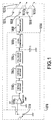
- FIGURE 2 shows a whole construction of the signal transmitter and receiver according to the once embodiment of the present invention.
- An audio signal which is supplied to an input terminal 11 is supplied with a limited 7 KHz band for example in a band elimination filter (BEF) 12.
- An output of the BEF 12 is applied to a multiplexer (MPX) 13.
- the audio signal and a digital data (mentioned after) are multiplexed in the MPX 13 and the multiplex signal is output from an output terminal 14.
- a digital data to be transmitted is applied to an input terminal 15 and a carrier is modulated in a modulator 16.
- the digital data signal output from the modulator 16 is limited its frequency band in a bandpass filter (BPF) 17 (BEF) and supplied to the MPX 13.
- BPF bandpass filter
- the carrier used in the modulator 16 is supplied from an input terminal via a gate 23.
- the gate 23 gates ON or OFF the passing of the carrier by a gate pulse GP supplied to an input terminal 22.
- the circuit makes it pass by each 0.5 sec. at 1 to 3 sec. intervals. Accordingly, the carrier is supplied to the modulator 16 by being a burst shape.
- the embodiment is using the burst state carrier, but it is needless to say that it can use a continuous carrier. Though a lot of variation will be possible as a gate pulse, the point is that the signal does not have a bad influence on other signals. Further, the BEF 12 limits a specified frequency region of the audio signal (the region where the digital data signal is multiplexed), however, it can depress only the period when the digital data signal is multiplexed by synchronizing with a timing of the gate pulse.
- the television channel audio signal multiplexed with the digital data in the audio frequency band is transmitted with a television signal through a process of the television transmitter.
- the digital data signal is extracted from the reproduced audio signal at the receiver.
- a demodulated audio signal is output from a loudspeaker of a television receiver 31.
- the digital data signal is multiplexed on the demodulated audio signal frequency band.
- the demodulated audio signal is picked up by a microphone 41, amplified in an amplifier 42 and then extracted by a bandpass filter (BPF) 43.
- BPF bandpass filter
- the extracted digital data signal is applied to a decoder 44.
- the decoder 44 carries out a demodulation by using a regenerated carrier.
- the demodulated data is supplied to an output terminal 45.
- the regenerated carrier is obtained as described hereinafter.
- An output of the bandpass filter 43 is applied to a synchronous separator 46, where the carrier is detected, that is the timing of the gate pulse is detected, and then a switch 47 is controlled to turn ON or OFF.
- a modulation signal is supplied into a phase locked loop circuit (PLL) 48 from the bandpass filter 43.
- the phase locked loop circuit 48 compares the phase of the regenerated carrier which is generated continuously in the circuit with the modulation signal supplied there, and locks the phase of the regenerated carrier to the carrier of the modulation signal.
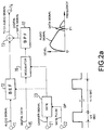
- FIGURE 3 shows a concrete embodiment of this invention.
- a PSK (phase shift keying) system is used for modulating and demodulating the digital data.
- An audio signal is supplied to an input terminal 11
- a digital data is supplied to an input terminal 15
- a gate pulse is supplied to an input terminal 22.
- a PSK modulator 121 comprises an oscillator 122 and a switch 123.
- the oscillator 122 outputs two carriers which reverse each other.
- the switch 123 selects one of the inverted phase carrier or non-inverted phase carrier according to whether the digital data is "0" or "1".
- the digital data signal output from the PSK modulator 121 is applied to the MPX 13 via a switch 125 which is turned ON by the gate pulse and a bandpass filter 126. Accordingly the multiplex signal of the digital data signal and the audio signal as shown in FIGURE 2 is able to be output from the output terminal 14.
- the signal is transmitted with a television signal, reproduced at a television receiver, output from a loudspeaker and picked up by a microphone.
- An output of a microphone 41 is amplified in an amplifier 42 and applied to a bandpass filter 43.
- the bandpass filter 43 By the bandpass filter 43 the digital data signal mentioned above (PSK modulated wave) is extracted.
- the digital data signal is supplied to a synchronous separator 46 and a switch 131.
- a gate pulse with a regular period is reproduced in the synchronous separator 46.
- the switch 131 is controlled by the gate pulse. According to this, a PSK modulation component (digital data signal) is provided from the switch 131, and applied to a PSK demodulator 132.
- the PSK demodulator 132 comprises a carrier regenerator 133 and the MPX 134.
- the digital data is demodulated in and output from the multiplier 134 and supplied to a latch 135.
- the latch 135 latches a data reproduced in the period which synchronizes the gate pulse.
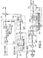
- FIGURE 4 shows another example of a concrete embodiment of this invention.
- a FSK frequency shift keying system is used for modulating and demodulation the digital data.
- the FSK modulator 140 comprises oscillators 141 and 142 having different oscillating frequencies and a switch 143 which select one of the outputs of these oscillators 141 and 142.
- the switch 143 selects one of the carriers output from the oscillators 141 and 142 according to whether the digital data is "0" or "1".
- the output (the digital data signal) of the FSK modulator 140 is applied to the MPX 13 via a switch 125 turned ON by the gate pulse and a bandpass filter 126. Accordingly, the multiplex signal of the digital data signal and the audio signal as explained in FIGURE 2 is able to obtained from the output terminal 14.
- the signal is transmitted with a television signal, reproduced at a television receiver, output from a loudspeaker and picked up by a microphone.
- An output of a microphone 41 is amplified in an amplifier 42 and applied to a bandpass filter 43.
- the bandpass filter 43 By the bandpass filter 43 the digital data signal mentioned above (FSK modulated wave) is extracted.
- the digital data signal is supplied to a synchronous separator 46 and a switch 131.
- a gate pulse with a regular period is reproduced in the synchronous separator 46.
- the switch 131 is controlled by the gate pulse. According to this, a FSK modulation component (digital data signal) is provided from the switch 131, and applied to a FSK demodulator 145.
- the FSK demodulator 145 comprises a delay unit 146, and output of the delay unit 146 and an exclusive OR gate 147.
- a demodulating data output from the FSK demodulator 145 is supplied to a latch 135.
- the latch 135 latches a data reproduced in the period which synchronizes the gate pulse.
- the modulation index of the FSK modulation is changed to 0.5 will be an MSK modulation. Since the frequency band of the modulated wave can be narrow ideally by using the MSK modulation it is possible to make obstruction to an audio signal smaller.
- the digital data receiver can be provided outside the television receiver, or it can also be provided in the television receiver. Further, the embodiment mentioned above uses the audio signal transmitting system of the television receiver, however, it is needless to say that it can be easily applied to the audio signal transmitting system of the radio.
- the audio signal for the data demodulation is picked up by the microphone 41, however, the present invention is not limited to this, it is also needless to say that the audio signal can be obtained by inserting a jack to an audio output line.
- the television receiver itself does not have to changed, and also it never limits the audio channel of the sound multiplex broadcast. Further, it never impair the reliability of receiving the data by suffering a surrounding disturbance to the transmitting medium at the receiver such as a data transmitting and receiving system by the raster modulation.
- a special information from a broadcast program sponsor can be mentioned as a case of the transmission of the digital data mentioned above.
- the broadcast program sponsor transmits a code for discounting a specified commodity (coupon code) in a commercial time
- an audience receives the coupon code as watching the commercial. That is, the fact that the coupon code was received indicates that the viewers have watched or listened the commercial.
- the viewers watch the coupon code on a display and take a note or make a memory to store the fact so as to be able to receive a discount service for commodities by presenting the coupon to a salesperson when they want to purchase the specified commodity.
- an information from a broadcasting station can be also mentioned as an example of the service data.
- a scheduled time for broadcasting the broadcast program or a subscription for a recording are changed the changed data are transmitted. Further it is possible to transmit a data for a time signal with information (time set for VTR e.g.). It also be possible to transmit information about a disaster, earthquake, typhoon, and a tsunami wave to general viewers.
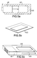
- FIGURES 5a to 5c are drawings showing a data processor for processing the demodulated data obtained in the receiver.
- FIGURE 5a shows that a receiver 401 explained in FIGURES 2 to 4 is provided in a housing 400, where a card shaped recording medium 402 for recording an output data is provided.
- the demodulation data is housed in the recording medium 402 when only a power supply of the system is put.
- FIGURE 5b shows a state that the recording medium 402 is drawn out of the receiver.
- the recording medium 402 is also used as a credit card at the salesperson.
- the discount code of the commodity is recorded there so that the consumer can demand the discount of the commodity when they purchase the commodity.
- FIGURE 5c shows an example that the receiver 401 is provided in the housing 400, the card shaped recording medium 402 has a slit 420 for allowing the insertion or withdrawal of the medium 402, and a display 430 is defined.
- the receiver displays the coupon code recorded in the recording medium 402 on the display 430 by inserting the card shaped recording medium 402 in the receiver and push a read-key 431. According to this the viewers can know what coupon they have.
- the viewers receive a discount service by presenting the recording medium 402 to a salesperson when they buy the commodities, after that the coupon code in the recording medium 402 is eliminated by the salesperson. So the salesperson has an apparatus to eliminate the coupon code in the recording medium.
- the present invention can transmit the digital data effectively without giving any interference or regulation to the transmitted signal and also can receive the data accurately.
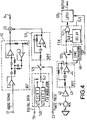
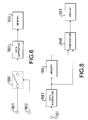
- FIGURE 6 is a circuit diagram for showing a first embodiment of this invention.
- a transmitting signal with which a digital data is multiplexed is supplied to an input terminal 1001 and applied to a data extractor 1003 via a switch 1005.
- the digital data is extracted from the transmitted signal in the data extractor 1003 and stored in a memory 1004.
- a control signal with an indication for preserving a data or not is supplied to an input terminal 1002 and it controls the switch 1005.
- the signal with which the digital data is multiplexed is applied to the data extractor 1003 so as to extract the data and stored in the memory 1004, when the indication to store the data is not shown, the signal is not supplied to the data extractor 1003.
- the digital data multiplexed with the transmitting signal is able to be extracted and stored only when the indication to preserve the data is shown.
- the switch 5 is located between the input terminal 1 and the data extractor 3.
- the memory 4 is not limited to be a semiconductor, but it can be any non-volatile memory means such as a magnetic recording medium.
- FIGURE 7 Another embodiment of the second aspect of the present invention will be explained hereinafter referring to a circuit diagram in FIGURE 7.
- the same components as these shown in FIGURE 6 are assigned with the same reference numerals.
- FIGURE 7 a transmitting signal with which a digital data is multiplexed is supplied to an input terminal 1001, the data is applied to a data extractor 1003.
- the digital data extracted in the data extractor 1003 is stored in a memory 1004.
- the time counting unit 1007 counts a specific time since the data output form the data extractor 1003 is started to be stored in the memory 1004.
- the deleting signal generating unit 1006 generates a deleting signal for deleting the digital data stored in the memory after a specific time since the data is stored in the memory 1004 by a signal from the time counting unit 1007.
- the deleting signal is supplied to the memory 1004 via a switch 1005.
- a control signal for showing whether it has an indication for preserving the data or not is supplied to so as to control the switch 1005. Accordingly, when the indication for storing the data for the specific time since the data is stored in the memory 1004 is not shown the deleting signal is supplied to the memory 1004 to delete the data. When the indication for storing the data is shown the deleting signal is not supplied to the memory 1004 so that the data is preserved as it is.
- the switch is located between the deleting signal generating means 1006 and the memory 1004 in this embodiment. However, it can be located the time counting unit 1007 and the deleting signal generating unit 1006. Further the digital data extracted after that can be superscripted instead of deleting the digital data stored in the memory 1004.
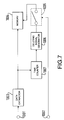
- FIGURE 8 A third embodiment of the second aspect of the present invention will be explained hereinafter referring to a circuit diagram in FIGURE 8.
- a transmitting signal with which the digital data is multiplexed is supplied to an input terminal 1001, the data is applied to a data extractor 1003.
- the digital data extracted in the data extractor 1003 is stored in a memory 1004.
- a comparator 1008 compares the digital data output from the data extractor 1003 with the data stored in the memory 1004. When these data are different they are displayed in a display device 1009.
- the same digital data is transmitted repeatedly in the same broadcast program or CM, other data is also transmitted repeatedly when the broadcast program or CM are changed. Transmitting the same data repeatedly is to receive the data whenever it fails the receiving in the receiver or in the broadcast program or CM.
- the data is always received and stored in the receiver and if the another data is received it is displayed in the display device, it is possible to let the viewer know about the change of the broadcast program or CM. and press the indication to preserve the data.
- the display device 1009 is not limited its display means. It can be also be adapted to LED display device, a code display to an audio or display part or a character display.
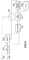
- FIGURE 9 A fourth embodiment of the second aspect of the present invention will be explained hereinafter referring to a circuit diagram in FIGURE 9.
- a transmitting signal with which the digital data is multiplexed is supplied to an input terminal 1001, the data is applied to a data extractor 1003.
- the digital data extracted in the data extractor 1003 is stored in a memory 1004.
- a comparator 1008 compares the digital data extracted in the data extractor 1003 with the data stored in the memory 1004.
- a time counting unit 1007 counts a specific time since the different data are applied to the comparator 1008, and displays a message to a display device 1009 in the meantime.
- a deleting signal generator 1006 generates a deleting signal for deleting the digital data stored in the memory 1004 by a signal from the time counting unit 1007 after a specific time since the different data are input. The deleting signal is supplied to the memory 1004 via a switch 1005.
- a control signal for showing whether it has an indication for preserving the data or not is supplied to, so as to control the switch 1005.
- the indication for preserving the data for the specific time since the different data are stored in the memory 4 is not shown the data is deleted and when the indication is shown the data is preserved as it is.
- the present invention can press the viewer for attention that if the data is preserved or not at the receiver, and it is possible to preserve the digital data only when the indication for preserving the data is shown.
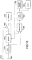
- FIGURE 10 is a circuit diagram for explaining a fifth embodiment of the second aspect of the present invention.
- a transmitting signal with which the digital data is multiplexed is supplied to an input terminal 1001, the data is applied to a data extractor 1003.
- the digital data extracted in the data extractor 1003 is stored in a memory 1010 through a switch 1005.
- a comparator 1008 compares the digital data extracted in the data extractor 1003 with the data stored in the memory 1004.
- a time counting unit 1007 counts a specific time since the different data are applied to the comparator 1008, and displays a message to a display device 1009 in the meantime.
- a deleting signal generator 1008 generates a deleting signal for deleting the digital data stored in the memory 1004 by a signal from the time counting unit 1007 after a specific time since the different data are input. The deleting signal is supplied to the memory 1004.
- a control signal for showing whether it has an indication for preserving the data or not is supplied to, so as to control the switch 5.
- the present invention can preserve the digital data stored in the memory 1004 to the memory 1010 only when the indication for preserving the data is shown for a specific time since the different data are applied to the comparator 1008.
- the present invention can press the viewer for attention that if the data is preserved or not at the receiver, and it is possible to preserve the digital data only when the indication for preserving the data is shown.
- the sponsor of the broadcast program transmits a code (coupon code) for discounting a specific commodity in the CM time by superposing with the CM viewer receives the coupon code as watching the CM. That the viewer received the coupon code proves that the viewer watched or listened the CM.
- the viewer is able to receive discount services by presenting the coupon code to the salesperson when the viewer buys the specific commodity by preserving the coupon code in the memory.
- the data cannot received without any person there when the data multiplexed with the broadcast program or CM is received, so that the present invention can prevent that viewer who did not watch the broadcast program or CM with which the data is multiplexed can receive the data or receive a privilege unfairnessly which is to be given to the person who watch the broadcast program or CM.
- the present invention can provide an extremely preferable signal transmitter and receiver.
Landscapes
- Engineering & Computer Science (AREA)
- Signal Processing (AREA)
- Television Systems (AREA)
Applications Claiming Priority (4)
| Application Number | Priority Date | Filing Date | Title |
|---|---|---|---|
| JP285363/94 | 1994-11-18 | ||
| JP6285363A JPH08149163A (ja) | 1994-11-18 | 1994-11-18 | 信号伝送装置及び受信装置及び方法 |
| JP222037/95 | 1995-08-30 | ||
| JP22203795A JPH0969820A (ja) | 1995-08-30 | 1995-08-30 | データ受信装置 |
Publications (1)
| Publication Number | Publication Date |
|---|---|
| EP0713301A2 true EP0713301A2 (de) | 1996-05-22 |
Family
ID=26524647
Family Applications (1)
| Application Number | Title | Priority Date | Filing Date |
|---|---|---|---|
| EP19950308292 Withdrawn EP0713301A2 (de) | 1994-11-18 | 1995-11-20 | Verfahren und Vorrichtung zur Übertragung von zusätzlichen Datensignalen als unhörbare Tonsignale in einem Tonsignal |
Country Status (2)
| Country | Link |
|---|---|
| EP (1) | EP0713301A2 (de) |
| KR (1) | KR960020437A (de) |
Cited By (4)
| Publication number | Priority date | Publication date | Assignee | Title |
|---|---|---|---|---|
| FR2759231A1 (fr) * | 1997-02-06 | 1998-08-07 | Info Tekcom | Procedes d'insertion et de decodage d'un message numerique dans un signal sonore, par exemple un morceau de musique, et dispositifs correspondants |
| FR2780228A1 (fr) * | 1998-06-18 | 1999-12-24 | Yves Cognet | Dispositif de transmission d'informations audio et video |
| WO2001082554A3 (en) * | 2000-04-27 | 2002-09-12 | Qualcomm Inc | System and method for extracting, decoding, and utilizing hidden data embedded in audio signals |
| WO2003007610A3 (en) * | 2001-07-13 | 2004-06-17 | Gemstar Dev Ltd | A television system with acoustic back-link |
Families Citing this family (1)
| Publication number | Priority date | Publication date | Assignee | Title |
|---|---|---|---|---|
| JP4534387B2 (ja) * | 2001-03-19 | 2010-09-01 | ソニー株式会社 | 記録装置および方法、再生装置および方法、記録媒体、プログラム、並びにディスク媒体 |
Citations (1)
| Publication number | Priority date | Publication date | Assignee | Title |
|---|---|---|---|---|
| US4807031A (en) | 1987-10-20 | 1989-02-21 | Interactive Systems, Incorporated | Interactive video method and apparatus |
-
1995
- 1995-11-17 KR KR1019950041832A patent/KR960020437A/ko not_active Ceased
- 1995-11-20 EP EP19950308292 patent/EP0713301A2/de not_active Withdrawn
Patent Citations (1)
| Publication number | Priority date | Publication date | Assignee | Title |
|---|---|---|---|---|
| US4807031A (en) | 1987-10-20 | 1989-02-21 | Interactive Systems, Incorporated | Interactive video method and apparatus |
Cited By (7)
| Publication number | Priority date | Publication date | Assignee | Title |
|---|---|---|---|---|
| FR2759231A1 (fr) * | 1997-02-06 | 1998-08-07 | Info Tekcom | Procedes d'insertion et de decodage d'un message numerique dans un signal sonore, par exemple un morceau de musique, et dispositifs correspondants |
| FR2780228A1 (fr) * | 1998-06-18 | 1999-12-24 | Yves Cognet | Dispositif de transmission d'informations audio et video |
| WO2001082554A3 (en) * | 2000-04-27 | 2002-09-12 | Qualcomm Inc | System and method for extracting, decoding, and utilizing hidden data embedded in audio signals |
| KR100766762B1 (ko) | 2000-04-27 | 2007-10-17 | 퀄컴 인코포레이티드 | 오디오 신호에 삽입된 은닉 데이터를 추출, 디코딩, 및 이용하기 위한 시스템 및 방법 |
| KR100770187B1 (ko) | 2000-04-27 | 2007-10-25 | 퀄컴 인코포레이티드 | 오디오 신호에 삽입된 은닉 데이터를 추출, 디코딩, 및이용하기 위한 시스템 및 방법 |
| US8462950B2 (en) | 2000-04-27 | 2013-06-11 | Qualcomm Incorporated | System and method for extracting, decoding, and utilizing hidden data embedded in audio signals |
| WO2003007610A3 (en) * | 2001-07-13 | 2004-06-17 | Gemstar Dev Ltd | A television system with acoustic back-link |
Also Published As
| Publication number | Publication date |
|---|---|
| KR960020437A (ko) | 1996-06-17 |
Similar Documents
| Publication | Publication Date | Title |
|---|---|---|
| US5663766A (en) | Digital data encoding in video signals using data modulated carrier signals at non-peaks in video spectra | |
| US4310854A (en) | Television captioning system | |
| KR970002962B1 (ko) | 대화식 비데오 방법 및 그 장치 | |
| US4605973A (en) | System, apparatus and method for recording and editing broadcast transmissions | |
| US6771316B1 (en) | Method and apparatus for selectively altering a televised video signal in real-time | |
| US4225967A (en) | Broadcast acknowledgement method and system | |
| US3492577A (en) | Audience rating system | |
| AU663087B2 (en) | Proadcast verification system | |
| US4520404A (en) | System, apparatus and method for recording and editing broadcast transmissions | |
| US4398216A (en) | Multiple signal transmission method and system, particularly for television | |
| CA2195037C (en) | System and method for encoding digital information in a television signal | |
| KR960002504B1 (ko) | 코드 삽입 영상신호 송수신회로 및 방법 | |
| GB2098833A (en) | Public alert and assistance systems | |
| JP2007181221A (ja) | 準備情報を伝送およびダウンロードするための方法及びその装置 | |
| KR20040106516A (ko) | 비상 경보 신호를 수신할 수 있는 텔레비전 신호 수신기 | |
| GB2232031A (en) | CATV display with superimposed character information | |
| EP0831606A2 (de) | Verfahren für die Übertragung eines Rundfunksignals, wie zum Beispiel ein Fernsehprogramm, mit einem Hauptprogramm und einem Zusatzprogramm für eine beschränkte Region, sowie Funksende- und -empfangsgerät für dieses Verfahren | |
| JPS61269596A (ja) | テレビジヨン視聴率調査方法および装置 | |
| EP0713301A2 (de) | Verfahren und Vorrichtung zur Übertragung von zusätzlichen Datensignalen als unhörbare Tonsignale in einem Tonsignal | |
| US5579391A (en) | TV scramble system for preventing illegal reception | |
| JPH1188280A (ja) | 放送サービスの案内システム | |
| US5612789A (en) | Video signal recorder and video apparatus with internal clock index signal | |
| JPH08149163A (ja) | 信号伝送装置及び受信装置及び方法 | |
| KR100308013B1 (ko) | 캡션을이용한광고시스템 | |
| US7185242B2 (en) | Digital display apparatus supporting error compensation and method thereof |
Legal Events
| Date | Code | Title | Description |
|---|---|---|---|
| PUAI | Public reference made under article 153(3) epc to a published international application that has entered the european phase |
Free format text: ORIGINAL CODE: 0009012 |
|
| 17P | Request for examination filed |
Effective date: 19951211 |
|
| AK | Designated contracting states |
Kind code of ref document: A2 Designated state(s): DE FR GB |
|
| STAA | Information on the status of an ep patent application or granted ep patent |
Free format text: STATUS: THE APPLICATION HAS BEEN WITHDRAWN |
|
| 18W | Application withdrawn |
Withdrawal date: 19970527 |