EP0713104A2 - Bohrlochtiefekorrelation und Rechnungsgerät und Verfahren zur Kombination von mehrere Bohrlochmessungen - Google Patents
Bohrlochtiefekorrelation und Rechnungsgerät und Verfahren zur Kombination von mehrere Bohrlochmessungen Download PDFInfo
- Publication number
- EP0713104A2 EP0713104A2 EP95116517A EP95116517A EP0713104A2 EP 0713104 A2 EP0713104 A2 EP 0713104A2 EP 95116517 A EP95116517 A EP 95116517A EP 95116517 A EP95116517 A EP 95116517A EP 0713104 A2 EP0713104 A2 EP 0713104A2
- Authority
- EP
- European Patent Office
- Prior art keywords
- downhole
- sensors
- sensor
- parameters
- depth
- Prior art date
- Legal status (The legal status is an assumption and is not a legal conclusion. Google has not performed a legal analysis and makes no representation as to the accuracy of the status listed.)
- Granted
Links
- 238000005259 measurement Methods 0.000 title claims abstract description 54
- 238000000034 method Methods 0.000 title claims abstract description 46
- 230000004044 response Effects 0.000 claims abstract description 110
- 230000002596 correlated effect Effects 0.000 claims description 26
- 239000000872 buffer Substances 0.000 claims description 19
- 230000007613 environmental effect Effects 0.000 claims description 7
- 230000001747 exhibiting effect Effects 0.000 claims description 5
- 238000013500 data storage Methods 0.000 claims description 3
- 230000001131 transforming effect Effects 0.000 claims 1
- 238000005553 drilling Methods 0.000 abstract description 28
- 230000006870 function Effects 0.000 abstract description 21
- 239000004020 conductor Substances 0.000 abstract description 6
- 230000008569 process Effects 0.000 abstract description 4
- 230000015572 biosynthetic process Effects 0.000 description 46
- 238000005755 formation reaction Methods 0.000 description 46
- 238000012545 processing Methods 0.000 description 14
- 230000008901 benefit Effects 0.000 description 10
- 230000000875 corresponding effect Effects 0.000 description 7
- 230000005540 biological transmission Effects 0.000 description 5
- 238000004891 communication Methods 0.000 description 5
- 238000011156 evaluation Methods 0.000 description 5
- 230000005251 gamma ray Effects 0.000 description 5
- 230000008859 change Effects 0.000 description 4
- 238000005516 engineering process Methods 0.000 description 4
- 230000035515 penetration Effects 0.000 description 4
- 238000003491 array Methods 0.000 description 2
- 238000001739 density measurement Methods 0.000 description 2
- 238000010586 diagram Methods 0.000 description 2
- 238000003672 processing method Methods 0.000 description 2
- 230000005855 radiation Effects 0.000 description 2
- 150000003839 salts Chemical class 0.000 description 2
- 239000004576 sand Substances 0.000 description 2
- 230000002269 spontaneous effect Effects 0.000 description 2
- 238000004441 surface measurement Methods 0.000 description 2
- XLYOFNOQVPJJNP-UHFFFAOYSA-N water Substances O XLYOFNOQVPJJNP-UHFFFAOYSA-N 0.000 description 2
- 238000012935 Averaging Methods 0.000 description 1
- 239000004215 Carbon black (E152) Substances 0.000 description 1
- 230000003044 adaptive effect Effects 0.000 description 1
- 230000002411 adverse Effects 0.000 description 1
- 230000000712 assembly Effects 0.000 description 1
- 238000000429 assembly Methods 0.000 description 1
- 238000006243 chemical reaction Methods 0.000 description 1
- 238000012937 correction Methods 0.000 description 1
- 230000007423 decrease Effects 0.000 description 1
- 238000013461 design Methods 0.000 description 1
- 238000013213 extrapolation Methods 0.000 description 1
- 239000000835 fiber Substances 0.000 description 1
- 238000001914 filtration Methods 0.000 description 1
- 239000012530 fluid Substances 0.000 description 1
- 238000000084 gamma-ray spectrum Methods 0.000 description 1
- 230000036541 health Effects 0.000 description 1
- 229930195733 hydrocarbon Natural products 0.000 description 1
- 125000001183 hydrocarbyl group Chemical group 0.000 description 1
- 229910052500 inorganic mineral Inorganic materials 0.000 description 1
- 238000007726 management method Methods 0.000 description 1
- 238000000691 measurement method Methods 0.000 description 1
- 239000011707 mineral Substances 0.000 description 1
- 238000010606 normalization Methods 0.000 description 1
- 230000000149 penetrating effect Effects 0.000 description 1
- 230000000704 physical effect Effects 0.000 description 1
- 239000002243 precursor Substances 0.000 description 1
- 230000000644 propagated effect Effects 0.000 description 1
- 238000000926 separation method Methods 0.000 description 1
- 239000012536 storage buffer Substances 0.000 description 1
- 238000012360 testing method Methods 0.000 description 1
- 238000012546 transfer Methods 0.000 description 1
Images


Classifications
-
- G—PHYSICS
- G01—MEASURING; TESTING
- G01V—GEOPHYSICS; GRAVITATIONAL MEASUREMENTS; DETECTING MASSES OR OBJECTS; TAGS
- G01V11/00—Prospecting or detecting by methods combining techniques covered by two or more of main groups G01V1/00 - G01V9/00
-
- G—PHYSICS
- G01—MEASURING; TESTING
- G01V—GEOPHYSICS; GRAVITATIONAL MEASUREMENTS; DETECTING MASSES OR OBJECTS; TAGS
- G01V3/00—Electric or magnetic prospecting or detecting; Measuring magnetic field characteristics of the earth, e.g. declination, deviation
- G01V3/38—Processing data, e.g. for analysis, for interpretation, for correction
Definitions
- This disclosure is directed in general toward the determination of geophysical and other parameters of interest by combining multiple sensor measurements obtained from within a borehole.
- Alternate embodiments of the invention include wireline operations in which telemetry capacity may be limited.
- the sensors are preferably axially spaced within a downhole subassembly which is located near the drill bit and is conveyed within the borehole with the drill string.
- Sensor responses are first correlated to a common depth reference and vertical resolution values, and then combined to obtain parameters of interest using downhole computing means.
- This disclosure is directed more specifically toward methods of depth correlation of multiple axially spaced sensors, vertical resolution matching of these sensors, and the combination of multiple sensor responses to obtain downhole computations of parameters of interest.
- computations are controlled for changing formation and borehole environmental conditions using commands from the surface.
- Computed parameters of interest are then telemetered to the surface in real time or stored downhole for subsequent retrieval.
- downhole depth correlation and resolution matching is a necessary precursor to meaningful downhole computations involving multiple sensor responses.
- U.S. Patent No. 3,638,484 to Maurice P. Tixier teaches the combination of neutron porosity, formation density, acoustic travel time, natural gamma radiation, spontaneous potential and resistivity wireline logs to obtain even more formation information including effective and shale fraction porosity.
- the first such combining "combination" logs were generated from individual logs, each being made with a given type of downhole sensor and an individual pass within the borehole. As the technology matured, multiple sensors of different types were combined within a single downhole instrument thereby allowing the input parameters of the combination log to be measured in a single pass within the borehole. This advancement provided advantages in that drilling rig time devoted to logging was reduced.
- MWD sensors are comparable to their wireline counterparts in spite of the harsh environment experienced in using such sensors in the drilling environment. It is feasible, at least in principle, to utilize multiple sensor, data intensive, combination logging methods developed for wireline tools to obtain new and improved parametric measurements while drilling. Furthermore, it is feasible, in principle, to utilize additional sensors responding to drilling related parameters simultaneously with formation evaluation type sensors. In practice, however, the combination of multiple sensor response techniques, comparable in sophistication to corresponding wireline applications, is limited by current MWD telemetry rates and downhole storage capacities. The simultaneous transmission of drilling dynamics sensor information such as directional information, weight on the drill bit, and other non-formation evaluation type measurements further overloads current MWD telemetry transmission rates which are of the order of 2 to 60 bits per second.
- MWD means for making formation evaluation combination logs comparable to current wireline logs require the computation of the desired parameters downhole, and the transfer of the computed parameters of interest to the surface.
- the transmission requirements are reduced by orders of magnitude in that only "answers" are telemetered, or alternately stored, rather than raw data.
- This type of downhole computation is also applicable to other types of non formation evaluation type measurements such as signals indicative of the operational characteristics of the downhole equipment as well as measurements indicative of drilling direction and efficiency.
- downhole processing is applicable to wireline systems with limited telemetry capacity.
- Nuclear detectors such as thermal neutron devices and scatter gamma ray devices used to obtain porosity and density measurements comprise a nuclear source and one or more radiation detector spaced axially from the source. The sensors respond primarily to formation between the source and the one or more detectors. The effective measure point is, therefore between the source and detectors.
- electromagnetic and acoustic sensors often comprise multiple, axially spaced, transmitters and receivers with the effective measure point lying within the axial within the axial array. Even electromagnetic sensors comprising a single transmitter and a single receiver with the transmitter operating at multiple frequencies can exhibit different effective measure points within a given formation.
- the effective measure point is not usually at the mid point of the axial array and, in fact, can vary with the type of intervening formation and/or the environmental conditions of the borehole such as the mud weight.
- the depth reference point is defined as the depth within the borehole at which the common reference point of the subassembly is positioned.
- Vertical resolutions of all sensors are also normalized to a common value as will be detailed in subsequent sections of this disclosure. If the effective measure points and vertical resolutions of the sensors are not properly correlated to a common reference, erroneous combination logs will result especially in the regions of bed boundaries where one or more sensors may be responding to one formation and the remaining sensors may be responding to different formations.
- the depth of the downhole subassembly or logging "sonde” is determined by passing the logging cable over a calibrated measure wheel at the surface of known circumference.
- the stretch of the cable is compensated for by the use of a microprocessor which uses as an input the length of cable in the borehole, the weight of the cable in the borehole, the weight of the sonde and even the history of the cable whose stretch characteristics can change with usage.
- Logging speed is also determined by the rate of rotation of the calibrated measure wheel.
- the depth and rate of penetration of the downhole subassembly is determined from a calibrated measure wheel which contacts the drill string at the surface. If logging sondes and downhole MWD subassemblies were conveyed smoothly along the borehole, multiple sensor responses could be correlated, at least to a first order of approximation, by simply shifting all sensor responses measured as a function of depth to a common reference point using the known physical spacings of the sensors and an assumed or computed effective measure point of each sensor. In practice, however, logging sondes and downhole MWD assemblies are not conveyed smoothly along the borehole.
- the lower sensor is in a thin formation bed and the upper sensor is in a relatively thick formation bed. If the sensors sporadically drops within the borehole, the upper sensor could move past the thin bed at an abnormally high velocity and obtain an abnormally small number of measurements within the this bed. The upper sensor could conceivably drop through the thin bed and obtain no measurements within the thin bed. If the surface measurement indicates a constant sensor array velocity, the log produced by the second sensor will indicate an abnormally thin formation bed or, conceivably indicate no bed if the second scenario is encountered. Any combination log computed from the combination of the two sensors responses would obviously be erroneous in the vicinity of the thin bed unless depth correlation methods are designed to handle such situations.
- the methods of wireline sensor correlation can be applied to the response of multiple MWD sensors.
- the application of these wireline techniques to MWD measurements has been prevented, however, by limited telemetry and downhole data storage capacity of current MWD systems, Using current MWD telemetry and storage capacity, raw sensor measurements exhibiting suitable vertical resolution can not be telemetered to the surface for correlation or, alternately, stored downhole for subsequent retrieval and processing.
- This disclosure is directed toward overcoming these problems so that MWD multiple sensor measurements can be properly correlated downhole n order to provide combination logs of maximum accuracy, precision and vertical resolution.
- the current invention is directed toward the use of a downhole computer and buffer storage within a MWD downhole subassembly to process data from the response of a plurality of sensors of different type.
- Alternate embodiments of the invention include wireline operations in which telemetry band width is limited by components such as a single conductor logging cable.
- Classes or types of sensors applicable to the invention include, but are not limited to, electromagnetic, acoustic, and nuclear.
- Sensor measurements are made essentially simultaneously.
- the sensor responses are correlated to a common reference point and reference vertical resolution. This correlation is performed using downhole models of the sensor responses stored within a first downhole storage means along with downhole computing means.
- response models are computed theoretically or are determined from sensor responses measured in test facilities with known environmental conditions. These sensor response models are initially stored within the first downhole storage means.
- sensor response models are calculated while drilling using the downhole computer and sensor responses in portions of the borehole where conditions are known. These models are then stored in the first downhole storage means and subsequently used for correlation in the portions of the borehole in which conditions are unknown.
- the depth and resolution correlated sensor responses are then processed, using combination sensor response models stored within the first storage means along with downhole computing means to obtain logs of formation parameters of interest as a function of depth within the borehole which is preferably a depth reference point.
- These computed log parameters are then transmitted to the surface by a suitable MWD telemetry system such as a mud pulsed system.
- the computed logs are stored in a second downhole data storage means of the MWD system for subsequent retrieval at the surface when the drill string is removed or "tripped" from the borehole.
- the answers are both telemetered to the surface and simultaneously stored within the second downhole storage means.
- a down link communication system is used to update parameters of the sensor response models and combination sensor response models based upon telemetered formation parameters telemetered to the surface.
- changes in borehole conditions such as increases or decreases in mud weight are telemetered to the downhole subassembly thereby updating sensor response and combination sensor response models for these changes in borehole conditions.
- the computer, buffer storage, first storage means, and second storage means are located within a MWD subassembly which is preferably located in the general vicinity of the drill bit.
- Sensors are also preferably located within the downhole subassembly as well as power supplies to furnish power to the computer, sensors, and control circuitry.
- the sensors are axially spaced along the axis of the downhole subassembly which is parallel to the axis of the borehole.
- the downhole subassembly is preferably a drill collar.
- the term "sensor" includes both the transmitter and receiver components for acoustic and electromagnetic sensors and nuclear source and detector for induced nuclear sensors.
- Raw responses from each sensor are collected over a relatively short depth interval which might be five to ten feet of borehole. These data are stored temporarily as a function of depth within the buffer storage and then retrieved and correlated, using the stored sensor response models and downhole computer, to a common depth and resolution reference point using sensor response models initially stored, or calculated downhole and subsequently stored, within a first downhole storage means and suitable correlation techniques. Correlated sensor data are next combined using the stored combination response model and the downhole computer to obtain the computed log parameters of interest. The resulting computed log parameters of interest are then telemetered to the surface where they are recorded as a function of the reference measure point of the sensor array. Alternately, the parameters of interest are stored within downhole memory as a function of depth for subsequent retrieval at the surface. The entire process is repeated sequentially as the sensor array is conveyed along the borehole. That is, the data array stored within the buffer is continually updated by the addition of new measurements while the least current elements of the array are discarded.
- the MWD systems acquires data as a function of time rather than depth using the embodiment with no down link communication between the surface and downhole subassemblies to transmit previously discussed depth measurements acquired at the surface.
- the correlation of raw sensor measurements and the computation of parameters of interest must be performed in the time domain and then converted to the depth domain when the parameters of interest are transferred to the surface either by telemetry or storage and subsequent retrieval, Alternately, raw sensor response can be collected and processed in the depth domain as originally described. This requires the use of a two way MWD telemetry system disclosed in a copending patent application filed and assigned to the assignee of the current disclosure.
- Depth and rate of penetration information measured at the surface is telemetered to the downhole subassembly thereby allowing the conversion of data processing from the time to the depth domain.
- the down link communication system can be used to update sensor response model parameters and sensor combination model parameters thereby improving the combination logs.
- depth correlation of multiple sensor responses not only involves depth shifting to a common measure point but also requires vertical resolution matching of responses either resulting from sporadic movement of the sensors along the borehole or from inherent differences in vertical resolution of the sensors.
- extrapolation techniques must be used or synthetic data must be generated. Synthetic data are generated from the combination of stored response models of the sensors which obtained no measurements within the bed and response models of the sensors which obtained measurements within the bed.
- An alternate solution to the latter problem is simply to indicate that no combination parameters could be computed in the bed with missing data. Such missing data is denoted as "no record" in seismology.
- One advantage is that raw data from a plurality of sensors can be correlated downhole to a reference point by using downhole buffer storage and computational means.
- Raw data can be depth correlated to a resolution approaching the inherent resolution of the sensors thereby greatly improving the accuracy and precision of subsequently computed combination logs. This feature is especially important in working in formations with thinly bedded zones.
- Prior art systems require that raw data be either telemetered to the surface for correlation or stored downhole for subsequent retrieval and correlation. Because of limited telemetry and storage capacity of current MWD systems, the vertical resolution of the telemetered or stored raw sensor data must be much coarser than the inherent vertical resolutions of the sensors. As a result, much vertical resolution is lost in subsequently computed combination logs.
- a further advantage of the current invention is that the downhole computational means can be used to directly compute the parameters of interest of the combination logs from downhole correlated raw sensor responses. Since the number of computed parameters or "answers" per unit depth of borehole is much smaller than the corresponding amount of raw sensor data used in the computation, usage of limited telemetry and storage capacity is further optimized by transferring only "answers" rather than raw data to the surface. When operating in the telemetry mode, the current invention can provide more computed log parameters with vastly improved vertical resolution. This feature is very important when the formations of interest comprise thinly laminated beds such as hydrocarbon bearing sand-shale sequences.
- a further advantage of the current invention is that additional parameters can be telemetered to the surface in real time since previously discussed downhole correlation and computational means conserve available telemetry capacity. These additional parameters might include drilling dynamics measurements or the operational status or "health" of all downhole measuring systems. This reduces drilling costs and insures that measured data and resulting computations are valid.
- a still further advantage of the current invention is that, when embodied with down link telemetry, changes such as variation in mud weight can be used to update sensor response model and combination sensor model parameters yielding more accurate combination logs with maximized vertical resolution.
- a further advantage of the current invention is that it is applicable to wireline systems which have limited telemetry band width such as those employing a single conductor logging cable. Additional advantages of the current invention will be defined and become apparent in following sections of this disclosure.
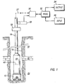
- Fig. 1 depicts the invention in a MWD embodiment
- the downhole subassembly 20 is suspended within borehole 14 by the drill string 16.
- the subassembly 20 is position as close as practical to the drill bit 12.
- the drill string is rotated by a kelly depicted by the numeral 26.
- the power source to drive the kelly as well as many other components of the surface drilling rig are not shown in order to clearly disclose the key elements of the invention.
- Data are telemetered from the downhole subassembly to an uphole telemetry element 30.
- the telemetry system can comprise one or more types of drilling fluid or "mud" pulse systems which are well known in the art.
- the data telemetry path is indicated by the broken line 27.
- Data from the downhole subassembly 20 are received by the up hole telemetry element 30 and passed to a surface processor 32.
- the processor controls the output 34 such that the parameters of interest are recorded and displayed in the desired manner which is usually a plot of the parameters of interest as a function of depth within the borehole at which they are determined.
- the processor 32 also receives data from the input element 36 which is telemetered downhole to subassembly 20 as will be discussed in subsequent sections.
- the processor 32 also receives depth information from the depth measure wheel and associated circuitry depicted by the numeral 28.
- the borehole 14 is shown as penetrating relatively thick formations 18 and 24 on either side of a relatively thin zone 22. This situation has been discussed earlier as well as the problems associated with measurements computed from multiple sensor responses should the sensors pass sporadically across such bedding.
- the effective measure point of the subassembly 20, as defined previously, is indicated by the numeral 40.
- Fig. 2 illustrates in block diagram form the major elements of the downhole subassembly 20 and further illustrated with arrows the paths of cooperation between the various elements. It should be understood that Fig. 2 illustrates only one physical arrangement of the elements and one system for cooperation between the elements. Other equally effective arrangements can be utilized to successfully practice the invention.
- a plurality of m sensors of one or more types arranged axially within the subassembly are identified by the numeral 52.
- a predetermined number of discrete data points output from the sensors 52 are stored within a buffer which, in Fig 2, is included as a partitioned portion of the memory capacity of the computer 50.
- the buffer storage means can comprise a separate memory element (not shown).
- the sensor response relationships or "models" are stored within memory means 48.
- the responses from sensors 52 are transformed into parameters of interest within the computer 50 using methods which will be detailed in the following section.
- the parameters of interest are then passed to the down hole portion of the telemetry system 42 and subsequently telemetered to the surface as illustrated generally by the broken line 27.
- the power sources 44 supply power to the telemetry element 42, the computer 50, the memory modules 46 and 48 and associated control circuits (not shown), and the sensors 52 and associated control circuits (not shown).
- Depth shifting will first be addressed and then resolution matching. Depth shifting accomplishes two purposes which are (1) the alignment of measure points of axially spaced sensors such that the sensor responses can be properly combined to obtain parameters of interest and (2) the measure of rate of penetration (ROP) of the bit 12 using only data obtained and processed downhole. Excursions of sensor responses to varying environmental conditions are a necessary condition for depth correlation. Responses of different types of sensors can be used in some situations for correlation, as will be subsequently illustrated. Correlation is, however, not possible if one sensor responds to a change in geophysical conditions while another sensor does not.
- the response of a gamma ray sensor would not change appreciably in crossing an oil/salt water interface within a sand of constant porosity.
- the response of a resistivity sensor would, however, vary significantly when crossing the interface. As a result, there would be no correlation across the oil/water interface.
- the crossing of a sand/shale interface by the two types of sensors would, in all probability, yield excellent excursions of both types of sensors.
- Fig. 3A depicts a portion of the downhole subassembly 20 comprising two electromagnetics sensors with each further comprising a transmitter and a receiver.
- the transmitter 140 and the receiver 144 comprise the first sensor with a measure point illustrated by the arrow 134.
- the transmitter 142 and the receiver 146 comprise the second sensor with a measure point illustrated by the arrow 134.
- the transmitter-receiver spacings for both sensors are the same for purposed of illustration.
- the separation of the two sensor measure points is defined as DD and is identified by the numeral 130.
- the response, r i of the first sensor array is plotted as a function of time in Fig. 3B.
- the response is depicted as a curve 150 with excursions identified by the numerals 157 and 155.
- Data over N discrete time intervals Dt, illustrated by the numeral 156, are collected and stored within the previously defined buffer storage means.
- the data r i are, therefore, discrete measures represented by the points 152 plotted at the mid point of each corresponding time interval Dt. In the illustrated example, Dt represents a time interval of 100 seconds.
- the response q i of the second sensor is shown in Fig. 3C as curve 160 plotted as a function of time.
- the curve 160 is actually an array N of discrete measurements 162 over time intervals Dt depicted by the numeral 162 and are likewise stored within the buffer memory. Excursions 167 and 165 correspond to the excursions 157 and 155 of curve 150, but occur at earlier times since the subassembly 20 is moving downhole during drilling and the second sensor "leads" the first sensor. For purposes of illustration, it will be assumed the N and Dt are the same for both the first and the second electromagnetic sensors although this is not a necessary condition for processing data according to the methods of the invention. Because of the different measure points 134 and 132 of the first and second sensors, respectively, all excursions of curve 150 will be displaced from corresponding excursions on curve 160 by a time differential DT, assuming that the ROP is constant over the correlated interval.
- the next step in the data processing sequence is to correlate the responses of the two electromagnetic sensors which, in this particular illustration, are still recorded in the time domain.
- Many correlation techniques can be used but the well known cross correlation technique is presented as the preferred embodiment.
- the N incremental measurements r i and q j are recalled from the buffer and C(j) is computed for each possible combination.
- DT 505 seconds.
- the computer 50 is programmed to automatically vary N and Dt based upon downhole computations of Dv without commands from the surface.
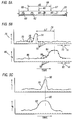
- Fig. 5A depicts a portion of the downhole subassembly comprising a nuclear sensor and an electromagnetic sensor. Only two sensors are used to illustrate this step of data processing although it should be understood that the techniques to be described are applicable to any number of sensor responses.
- the nuclear sensor comprises a nuclear source 60 and a nuclear detector 62.
- the effective measure point of the nuclear sensor array is denoted by the arrow 65.
- the electromagnetic sensor used in the example comprises a single transmitter 66 and a single receiver 64.
- the effective measure point for the electromagnetic sensor array is denoted by the arrow 67.
- the two effective measure points are displaced axially along subassembly 20 by the known distance, again defined as DD identified by the numeral 68.
- the response, r i of the nuclear sensor is plotted as a function of time in Fig. 5B.
- the response is depicted as a curve 70 with a major excursion 74 induced possibly by a thin formation 22 as illustrated in Fig. 1.
- Data over N discrete time intervals Dt, where Dts are illustrated by the numeral 72, are collected and stored within the previously defined buffer storage means.
- the data r i are again discrete measures represented by the points 76 plotted at the mid point of each corresponding time interval Dt.
- the response q i of the electromagnetic sensor is likewise shown in Fig 5B as curve 80 plotted as a function of time.
- An excursion 84 is depicted which exhibits poorer vertical resolution than the nuclear sensor across the same geological feature.
- the curve 80 like curve 70, is actually an array N of discrete measurements 85 over time intervals Dt depicted by the numeral 82 and are likewise stored within the buffer memory.
- N and Dt are the same for both the nuclear and electromagnetic sensors although this is not a necessary condition for processing data according to the methods of the invention.
- the excursions 74 and 84 are displaced by a time differential DT denoted by the numeral 79.
- the next step in the data processing sequence is to depth shift the responses of the nuclear and electromagnetic sensors using the cross correlation described in the previous example. Results of depth shifting are illustrated in Fig 5C where the line 90 denotes a time which corresponds to the effective measure point of the combine sensor array in the depth domain.
- Absolute depth can be supplied to the downhole computer at several stages of the drilling operation. As examples, absolute depth can be supplied each time the mud pump is cycled, or each time the drill bit is tripped, or both. The preferred method is to supply absolute depth information each time the mud pump is cycled which, of course, occurs each time a joint of drill pipe is added to the drill string and possibly more often. Subsequent incremental depth commands based upon the readings of the surface depth indicator 28 are telemetered down to the computer by means of the computer down link element 30.
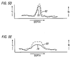
- Fig. 5D illustrates the nuclear and electromagnetic sensor data which have been resolution matched by using a response model of the electromagnetic sensor, stored within memory module 48, to "sharpen” the resolution of the electromagnetic sensor as depicted by curve 82 to match the resolution of the nuclear sensor, identified again by the numeral 70.
- the response of the nuclear sensor is smeared by averaging a subset of u elements within the larger set N using the relationship and plotting the smeared response r' i at the mid point of depth increment u.
- the result of this type of resolution matching is shown in Fig 5E where the vertical resolution of the response of the nuclear sensor 74 has been degraded to match the resolution of the electromagnetic sensor as depicted by curve 80.
- Geophysical, drilling dynamics and other parameters of interest are now determined by combining these responses using combination sensor response models which are stored either internally within the computer 50 or within an additional memory module (not shown) contained within the downhole subassembly 20.
- the computed parameters of interest are telemetered to the surface by means of the telemetry element 42 cooperating with telemetry element 30.
- Computed parameters of interest are displayed in an appropriate form as a function of depth by output element 34.
- the parameters of interest can be stored downhole within memory module 46 for subsequent retrieval at the surface when the drill string is tripped.
- An additional option is to both telemeter to the surface and store either all or portions of the computed parameters of interest.
- step 100 the known spacings between the effective points of a plurality of sensors, the number of data points N from each sensor to be stored in the storage buffer, and the incremental time intervals over which raw data will be accumulated are stored in the downhole computer 50.
- N data points are acquired for each sensor as depicted at step 102.
- step 104 a decision is made whether to convert the N raw data points into engineering units prior to correlation or whether to correlate raw data.
- an "engineering unit" is defined by example using the response of a epithermal neutron porosity sensor.
- Raw data from the sensor would be counting rate which would exhibit excursions as the formation parameters vary.
- Apparent formation porosity computed from measured counting rate using a predetermined calibration relationship (i.e. the sensor response model) between counting rate and porosity, is defined as the sensor response in "engineering" units. Apparent porosity will also yield correlatable excursions. If the decision is made to correlate raw data, which is preferred in that less computing capacity is required, correlation is made at step 106. The correlated data are converted from the time to depth domain at step 108. Sensor resolution is matched at step 110. At step 112, raw sensor data for the N/2 depth point in buffer storage are converted to corresponding engineering units using sensor response model stored in memory module 48.
- step 112 is omitted and raw sensor data are combined directly to obtain the parameters of interest. Parameters are telemetered to the surface or alternately stored downhole for subsequent retrieval at step 116.
- step 118 the arrays of N elements for each sensor are updated as the sensors move along the borehole by discarding the "oldest" measurements and adding the most recent measurements. The process is repeated sequentially again starting at step 102. If, at step 104, the decision is made to correlate sensor response in engineering units, sensor responses are converted at step 120 to the corresponding engineering units for each set of N data points in buffer storage. Correlation is performed at step 122 in the time domain and the correlated data are converted to the depth domain at step 124. Sensor resolution is matched at step 126 and the steps depicted in blocks 114 through 118 have been described previously.
Landscapes
- Life Sciences & Earth Sciences (AREA)
- Physics & Mathematics (AREA)
- General Life Sciences & Earth Sciences (AREA)
- General Physics & Mathematics (AREA)
- Geophysics (AREA)
- Engineering & Computer Science (AREA)
- Environmental & Geological Engineering (AREA)
- Geology (AREA)
- Remote Sensing (AREA)
- Geophysics And Detection Of Objects (AREA)
Applications Claiming Priority (2)
| Application Number | Priority Date | Filing Date | Title |
|---|---|---|---|
| US08/326,829 US5581024A (en) | 1994-10-20 | 1994-10-20 | Downhole depth correlation and computation apparatus and methods for combining multiple borehole measurements |
| US326829 | 1994-10-20 |
Publications (3)
| Publication Number | Publication Date |
|---|---|
| EP0713104A2 true EP0713104A2 (de) | 1996-05-22 |
| EP0713104A3 EP0713104A3 (de) | 1998-05-06 |
| EP0713104B1 EP0713104B1 (de) | 2002-08-28 |
Family
ID=23273892
Family Applications (1)
| Application Number | Title | Priority Date | Filing Date |
|---|---|---|---|
| EP95116517A Expired - Lifetime EP0713104B1 (de) | 1994-10-20 | 1995-10-19 | Bohrlochtiefekorrelation- und -Rechnungsgerät und Verfahren zur Kombination von mehreren Bohrlochmessungen |
Country Status (4)
| Country | Link |
|---|---|
| US (1) | US5581024A (de) |
| EP (1) | EP0713104B1 (de) |
| CA (1) | CA2160968C (de) |
| NO (1) | NO316345B1 (de) |
Cited By (8)
| Publication number | Priority date | Publication date | Assignee | Title |
|---|---|---|---|---|
| WO1998017894A3 (en) * | 1996-10-22 | 1998-07-16 | Baker Hughes Inc | Drilling system with integrated bottom hole assembly |
| GB2317406B (en) * | 1996-09-23 | 1999-07-14 | Baker Hughes Inc | Well control systems employing downhole network |
| GB2334108A (en) * | 1996-10-22 | 1999-08-11 | Baker Hughes Inc | Drilling system with integrated bottom hole assembly |
| WO2003096075A1 (en) * | 2002-05-13 | 2003-11-20 | Camco International (Uk) Limited | Recalibration of downhole sensors |
| EP1306694A3 (de) * | 2001-10-26 | 2004-07-21 | Statoil ASA | Verfahren zum Kombinieren von räumlichen Modellen |
| EP1718994A4 (de) * | 2004-02-24 | 2015-07-08 | Kjt Entpr Inc | Kombiniertes elektromagnetisches messsystem für oberflächen und bohrlöcher sowie system und verfahren zur bestimmung der formationsflüssigkeitseigenschaften |
| WO2018101842A1 (en) * | 2016-12-02 | 2018-06-07 | Statoil Petroleum As | Sensor for a downhole tool |
| WO2018195010A1 (en) * | 2017-04-17 | 2018-10-25 | Schlumberger Technology Corporation | Method for movement measurement of an instrument in a wellbore |
Families Citing this family (72)
| Publication number | Priority date | Publication date | Assignee | Title |
|---|---|---|---|---|
| US5812068A (en) * | 1994-12-12 | 1998-09-22 | Baker Hughes Incorporated | Drilling system with downhole apparatus for determining parameters of interest and for adjusting drilling direction in response thereto |
| US6088294A (en) * | 1995-01-12 | 2000-07-11 | Baker Hughes Incorporated | Drilling system with an acoustic measurement-while-driving system for determining parameters of interest and controlling the drilling direction |
| DE59609594D1 (de) * | 1996-06-07 | 2002-10-02 | Baker Hughes Inc | Verfahren und Vorrichtung zur unterirdischen Erfassung der Teufe einer Bohrung |
| FR2750159B1 (fr) * | 1996-06-24 | 1998-08-07 | Inst Francais Du Petrole | Methode et systeme d'estimation en temps reel d'au moins un parametre lie au comportement d'un outil de fond de puits |
| FR2750160B1 (fr) * | 1996-06-24 | 1998-08-07 | Inst Francais Du Petrole | Methode et systeme d'estimation en temps reel d'au moins un parametre lie au deplacement d'un outil de forage |
| US6691779B1 (en) | 1997-06-02 | 2004-02-17 | Schlumberger Technology Corporation | Wellbore antennae system and method |
| US6693553B1 (en) * | 1997-06-02 | 2004-02-17 | Schlumberger Technology Corporation | Reservoir management system and method |
| US6176323B1 (en) | 1997-06-27 | 2001-01-23 | Baker Hughes Incorporated | Drilling systems with sensors for determining properties of drilling fluid downhole |
| US6237404B1 (en) * | 1998-02-27 | 2001-05-29 | Schlumberger Technology Corporation | Apparatus and method for determining a drilling mode to optimize formation evaluation measurements |
| FR2788135B1 (fr) * | 1998-12-30 | 2001-03-23 | Schlumberger Services Petrol | Procede d'obtention d'une image bidimensionnelle developpee de la paroi d'un forage |
| US7407006B2 (en) | 1999-01-04 | 2008-08-05 | Weatherford/Lamb, Inc. | System for logging formations surrounding a wellbore |
| US6736210B2 (en) * | 2001-02-06 | 2004-05-18 | Weatherford/Lamb, Inc. | Apparatus and methods for placing downhole tools in a wellbore |
| US7513305B2 (en) | 1999-01-04 | 2009-04-07 | Weatherford/Lamb, Inc. | Apparatus and methods for operating a tool in a wellbore |
| US6151961A (en) * | 1999-03-08 | 2000-11-28 | Schlumberger Technology Corporation | Downhole depth correlation |
| GB9913356D0 (en) * | 1999-06-08 | 1999-08-11 | Schlumberger Holdings | Methods of identifying fluid types of underground formations |
| US6344746B1 (en) * | 1999-12-03 | 2002-02-05 | Baker Hughes Incorporated | Method for processing the lapse measurements |
| GB2357097A (en) * | 1999-12-08 | 2001-06-13 | Norske Stats Oljeselskap | Method of assessing positional uncertainty in drilling a well |
| US6543280B2 (en) * | 2000-07-07 | 2003-04-08 | Inertial Response, Inc. | Remote sensing and measurement of distances along a borehole |
| US6703837B1 (en) | 2000-09-15 | 2004-03-09 | Precision Drilling Technology Services Group, Inc. | Wellbore resistivity tool with simultaneous multiple frequencies |
| US6516663B2 (en) * | 2001-02-06 | 2003-02-11 | Weatherford/Lamb, Inc. | Downhole electromagnetic logging into place tool |
| US6467341B1 (en) | 2001-04-24 | 2002-10-22 | Schlumberger Technology Corporation | Accelerometer caliper while drilling |
| US6557630B2 (en) | 2001-08-29 | 2003-05-06 | Sensor Highway Limited | Method and apparatus for determining the temperature of subterranean wells using fiber optic cable |
| US6909667B2 (en) * | 2002-02-13 | 2005-06-21 | Halliburton Energy Services, Inc. | Dual channel downhole telemetry |
| US6833706B2 (en) * | 2002-04-01 | 2004-12-21 | Schlumberger Technology Corporation | Hole displacement measuring system and method using a magnetic field |
| US8612193B2 (en) * | 2002-05-21 | 2013-12-17 | Schlumberger Technology Center | Processing and interpretation of real-time data from downhole and surface sensors |
| GB2385923B (en) * | 2002-05-24 | 2004-07-28 | Statoil Asa | System and method for electromagnetic wavefield resolution |
| EP1429157B1 (de) * | 2002-12-13 | 2009-10-14 | Service Pétroliers Schlumberger | Verfahren und Vorrichtung zur verbesserten Tiefenanpassung von Bohrlochbildern oder Probenbildern |
| US6885942B2 (en) * | 2003-01-09 | 2005-04-26 | Schlumberger Technology Corporation | Method to detect and visualize changes in formation parameters and borehole condition |
| US6876721B2 (en) * | 2003-01-22 | 2005-04-05 | Saudi Arabian Oil Company | Method for depth-matching using computerized tomography |
| GB2399640B (en) | 2003-03-17 | 2007-02-21 | Statoil Asa | Method and apparatus for determining the nature of submarine reservoirs |
| US7020557B2 (en) * | 2003-12-31 | 2006-03-28 | Schlumberger Technology Corporation | Method and apparatus for correcting the depth index for well-log data using pressure measurements |
| GB2409900B (en) | 2004-01-09 | 2006-05-24 | Statoil Asa | Processing seismic data representing a physical system |
| US9441476B2 (en) | 2004-03-04 | 2016-09-13 | Halliburton Energy Services, Inc. | Multiple distributed pressure measurements |
| WO2005091019A1 (en) * | 2004-03-04 | 2005-09-29 | Halliburton Energy Services, Inc. | Multiple distributed force measurements |
| US20060180349A1 (en) * | 2005-02-16 | 2006-08-17 | Baker Hughes Incorporated | Time and depth correction of MWD and wireline measurements using correlation of surface and downhole measurements |
| US7649169B2 (en) * | 2005-03-21 | 2010-01-19 | Baker Hughes Incorporated | Method for determining shale bed boundaries and gamma ray activity with gamma ray instrument |
| GB2434868B (en) | 2006-02-06 | 2010-05-12 | Statoil Asa | Method of conducting a seismic survey |
| GB2435693A (en) | 2006-02-09 | 2007-09-05 | Electromagnetic Geoservices As | Seabed electromagnetic surveying |
| GB2439378B (en) | 2006-06-09 | 2011-03-16 | Electromagnetic Geoservices As | Instrument for measuring electromagnetic signals |
| US8528637B2 (en) | 2006-09-20 | 2013-09-10 | Baker Hughes Incorporated | Downhole depth computation methods and related system |
| US8122954B2 (en) * | 2006-09-20 | 2012-02-28 | Baker Hughes Incorporated | Downhole depth computation methods and related system |
| US8899322B2 (en) * | 2006-09-20 | 2014-12-02 | Baker Hughes Incorporated | Autonomous downhole control methods and devices |
| GB2442749B (en) | 2006-10-12 | 2010-05-19 | Electromagnetic Geoservices As | Positioning system |
| US7654341B2 (en) * | 2006-10-26 | 2010-02-02 | Tt Technologies, Inc. | Drill stem coupling and method for a directional drill |
| US8902695B2 (en) * | 2006-12-06 | 2014-12-02 | Baker Hughes Incorporated | Apparatus and method for clock shift correction for measurement-while-drilling measurements |
| GB2445582A (en) | 2007-01-09 | 2008-07-16 | Statoil Asa | Method for analysing data from an electromagnetic survey |
| US20080180322A1 (en) * | 2007-01-26 | 2008-07-31 | Mohammad Mojahedul Islam | Method and system for wireless tracking of utility assets |
| US9638022B2 (en) * | 2007-03-27 | 2017-05-02 | Halliburton Energy Services, Inc. | Systems and methods for displaying logging data |
| US7610960B2 (en) * | 2007-04-25 | 2009-11-03 | Baker Hughes Incorporated | Depth correlation device for fiber optic line |
| BRPI0908566B1 (pt) * | 2008-03-03 | 2021-05-25 | Intelliserv International Holding, Ltd | Método de monitoramento das condições de furo abaixo em um furo de sondagem penetrando uma formação subterrânea |
| US7823658B2 (en) * | 2008-05-09 | 2010-11-02 | Baker Hughes Incorporated | Analyzing resistivity images for determining downhole events and removing image artifacts |
| GB2468224B (en) | 2008-08-21 | 2012-07-18 | Halliburton Energy Serv Inc | Automated log quality monitoring systems and methods |
| US8312320B2 (en) * | 2008-08-25 | 2012-11-13 | Saudi Arabian Oil Company | Intelligent field oil and gas field data acquisition, delivery, control, and retention based apparatus, program product and related methods |
| BRPI0822365B1 (pt) * | 2008-11-19 | 2019-04-24 | Halliburton Energy Services Inc. | Conjunto de ferramenta de fundo de furo, e, método para perfilar |
| US10041343B2 (en) | 2009-06-02 | 2018-08-07 | Halliburton Energy Services, Inc. | Micro-sonic density imaging while drilling systems and methods |
| US9238958B2 (en) * | 2009-09-10 | 2016-01-19 | Baker Hughes Incorporated | Drill bit with rate of penetration sensor |
| US20110203805A1 (en) * | 2010-02-23 | 2011-08-25 | Baker Hughes Incorporated | Valving Device and Method of Valving |
| US8481920B2 (en) * | 2011-07-19 | 2013-07-09 | Baker Hughes Incorporated | Apparatus and method for determining formation density from nuclear density measurements made using sensors at more than one location |
| US9500762B2 (en) | 2011-09-19 | 2016-11-22 | Precision Energy Services, Inc. | Borehole resistivity imager using discrete energy pulsing |
| GB2500584B (en) | 2012-03-23 | 2014-02-26 | Reeves Wireline Tech Ltd | Improvements in or relating to log inversion |
| WO2014194305A1 (en) * | 2013-05-31 | 2014-12-04 | Kongsberg Oil & Gas Technologies Inc. | System and method for combining curves in oilfield drilling and production operations |
| CA2931182C (en) | 2013-12-23 | 2019-01-15 | Halliburton Energy Services, Inc. | Wellbore tubular length determination using pulse-echo measurements |
| US10801315B2 (en) | 2015-10-28 | 2020-10-13 | Halliburton Energy Services, Inc. | Degradable isolation devices with data recorders |
| US10197695B2 (en) * | 2016-02-17 | 2019-02-05 | Baker Hughes, A Ge Company, Llc | Method and apparatus for estimating formation properties using transient electromagnetic measurements while drilling |
| US10156655B2 (en) | 2016-03-08 | 2018-12-18 | Baker Hughes, A Ge Company, Llc | Method and apparatus for measurement of pipe signals for downhole transient electromagnetic processing |
| US10261210B2 (en) | 2016-03-09 | 2019-04-16 | Baker Hughes, A Ge Company, Llc | Method and apparatus for active suppression of pipe signals in transient electromagnetic measurements |
| US10162076B2 (en) | 2016-03-14 | 2018-12-25 | Baker Hughes, A Ge Company, Llc | Method and apparatus for correction of transient electromagnetic signals to remove a pipe response |
| WO2019157242A1 (en) | 2018-02-08 | 2019-08-15 | Schlumberger Technology Corporation | Ultrasonic acoustic sensors for measuring formation velocities |
| CN111742243B (zh) | 2018-02-08 | 2024-06-04 | 斯伦贝谢技术有限公司 | 用于测量地层速度的超声换能器 |
| US11346213B2 (en) * | 2018-05-14 | 2022-05-31 | Schlumberger Technology Corporation | Methods and apparatus to measure formation features |
| US10564109B1 (en) | 2019-08-19 | 2020-02-18 | Saudi Arabian Oil Company | Systems and methods for core data shifting |
| US11867051B2 (en) | 2020-02-20 | 2024-01-09 | Baker Hughes Oilfield Operations Llc | Incremental downhole depth methods and systems |
Family Cites Families (25)
| Publication number | Priority date | Publication date | Assignee | Title |
|---|---|---|---|---|
| US3209323A (en) * | 1962-10-02 | 1965-09-28 | Texaco Inc | Information retrieval system for logging while drilling |
| US3590228A (en) * | 1967-10-02 | 1971-06-29 | Schlumberger Technology Corp | Methods and apparatus for processing well logging data |
| US3638484A (en) * | 1968-11-05 | 1972-02-01 | Schlumberger Technology Corp | Methods of processing well logging data |
| US3721960A (en) * | 1969-07-14 | 1973-03-20 | Schlumberger Technology Corp | Methods and apparatus for processing well logging data |
| US3720912A (en) * | 1969-12-11 | 1973-03-13 | Schlumberger Technology Corp | Methods for investigating earth formations |
| US4327412A (en) * | 1972-07-31 | 1982-04-27 | Schlumberger Limited | Well logging data processing technique |
| US4276599A (en) * | 1972-07-31 | 1981-06-30 | Schlumberger Technology Corporation | Method of processing well logging data |
| US4310887A (en) * | 1972-08-28 | 1982-01-12 | Schlumberger Technology Corporation | Verification and calibration of well logs and reconstruction of logs |
| US4320469A (en) * | 1973-05-09 | 1982-03-16 | Schlumberger Technology Corporation | Well logging: depth correlation of logs |
| GB2035554B (en) * | 1978-10-10 | 1983-08-17 | Dresser Ind | Well logging system and method |
| US4297879A (en) * | 1979-07-02 | 1981-11-03 | Howells Anthony P | Well logging correlation method and apparatus |
| US4541275A (en) * | 1983-09-19 | 1985-09-17 | Dresser Industries, Inc. | Log correlation method and apparatus |
| US4697650A (en) * | 1984-09-24 | 1987-10-06 | Nl Industries, Inc. | Method for estimating formation characteristics of the exposed bottomhole formation |
| US4833914A (en) * | 1988-04-29 | 1989-05-30 | Anadrill, Inc. | Pore pressure formation evaluation while drilling |
| US5064006A (en) * | 1988-10-28 | 1991-11-12 | Magrange, Inc | Downhole combination tool |
| US5230387A (en) * | 1988-10-28 | 1993-07-27 | Magrange, Inc. | Downhole combination tool |
| US4958073A (en) * | 1988-12-08 | 1990-09-18 | Schlumberger Technology Corporation | Apparatus for fine spatial resolution measurments of earth formations |
| US5065099A (en) * | 1990-02-02 | 1991-11-12 | Halliburton Logging Services, Inc. | Coil array for a high resolution induction logging tool and method of logging an earth formation |
| US5159577A (en) * | 1990-10-09 | 1992-10-27 | Baroid Technology, Inc. | Technique for reducing whirling of a drill string |
| FR2669742B1 (fr) * | 1990-11-23 | 1993-03-26 | Schlumberger Services Petrol | Procede et dispositif de gestion de signaux pour appareil de diagraphie. |
| FR2670531B1 (fr) * | 1990-12-12 | 1993-02-19 | Inst Francais Du Petrole | Methode et dispositif pour mesurer la vitesse d'avancement d'un equipement progressant dans un puits. |
| US5250806A (en) * | 1991-03-18 | 1993-10-05 | Schlumberger Technology Corporation | Stand-off compensated formation measurements apparatus and method |
| US5377105A (en) * | 1991-04-12 | 1994-12-27 | Halliburton Logging Services | Enhanced vertical resolution processing of dual-spaced neutron and density tools |
| US5332048A (en) * | 1992-10-23 | 1994-07-26 | Halliburton Company | Method and apparatus for automatic closed loop drilling system |
| US5329235A (en) * | 1992-11-02 | 1994-07-12 | Western Atlas International, Inc. | Method for processing signals from an MWD electromagnetic resistivity logging tool |
-
1994
- 1994-10-20 US US08/326,829 patent/US5581024A/en not_active Expired - Lifetime
-
1995
- 1995-10-19 CA CA002160968A patent/CA2160968C/en not_active Expired - Lifetime
- 1995-10-19 EP EP95116517A patent/EP0713104B1/de not_active Expired - Lifetime
- 1995-10-19 NO NO19954176A patent/NO316345B1/no not_active IP Right Cessation
Cited By (14)
| Publication number | Priority date | Publication date | Assignee | Title |
|---|---|---|---|---|
| GB2317406B (en) * | 1996-09-23 | 1999-07-14 | Baker Hughes Inc | Well control systems employing downhole network |
| GB2334108A (en) * | 1996-10-22 | 1999-08-11 | Baker Hughes Inc | Drilling system with integrated bottom hole assembly |
| GB2334108B (en) * | 1996-10-22 | 2001-03-21 | Baker Hughes Inc | Drilling system with integrated bottom hole assembly |
| WO1998017894A3 (en) * | 1996-10-22 | 1998-07-16 | Baker Hughes Inc | Drilling system with integrated bottom hole assembly |
| EP1306694A3 (de) * | 2001-10-26 | 2004-07-21 | Statoil ASA | Verfahren zum Kombinieren von räumlichen Modellen |
| GB2405483A (en) * | 2002-05-13 | 2005-03-02 | Camco Internat | Recalibration of downhole sensors |
| WO2003096075A1 (en) * | 2002-05-13 | 2003-11-20 | Camco International (Uk) Limited | Recalibration of downhole sensors |
| GB2405483B (en) * | 2002-05-13 | 2005-09-14 | Camco Internat | Recalibration of downhole sensors |
| EP1718994A4 (de) * | 2004-02-24 | 2015-07-08 | Kjt Entpr Inc | Kombiniertes elektromagnetisches messsystem für oberflächen und bohrlöcher sowie system und verfahren zur bestimmung der formationsflüssigkeitseigenschaften |
| WO2018101842A1 (en) * | 2016-12-02 | 2018-06-07 | Statoil Petroleum As | Sensor for a downhole tool |
| GB2573432A (en) * | 2016-12-02 | 2019-11-06 | Equinor Energy As | Sensor for a downhole tool |
| US10947834B2 (en) | 2016-12-02 | 2021-03-16 | Equinor Energy As | Sensor for a downhole tool |
| GB2573432B (en) * | 2016-12-02 | 2021-12-08 | Equinor Energy As | Sensor for a downhole tool |
| WO2018195010A1 (en) * | 2017-04-17 | 2018-10-25 | Schlumberger Technology Corporation | Method for movement measurement of an instrument in a wellbore |
Also Published As
| Publication number | Publication date |
|---|---|
| NO954176D0 (no) | 1995-10-19 |
| CA2160968C (en) | 2006-05-23 |
| NO954176L (no) | 1996-04-22 |
| EP0713104B1 (de) | 2002-08-28 |
| CA2160968A1 (en) | 1996-04-21 |
| NO316345B1 (no) | 2004-01-12 |
| US5581024A (en) | 1996-12-03 |
| EP0713104A3 (de) | 1998-05-06 |
Similar Documents
| Publication | Publication Date | Title |
|---|---|---|
| US5581024A (en) | Downhole depth correlation and computation apparatus and methods for combining multiple borehole measurements | |
| US6272434B1 (en) | Drilling system with downhole apparatus for determining parameters of interest and for adjusting drilling direction in response thereto | |
| EP0654687B1 (de) | Verarbeitungsverfahren von Bohrlochmessung-während-des-Bohrens-Daten | |
| US10928537B2 (en) | Prediction of formation and stratigraphic layers while drilling | |
| US6184685B1 (en) | Mulitiple spacing resistivity measurements with receiver arrays | |
| US5678643A (en) | Acoustic logging while drilling tool to determine bed boundaries | |
| US6353321B1 (en) | Uncompensated electromagnetic wave resistivity tool for bed boundary detection and invasion profiling | |
| US9182509B2 (en) | System and method for generating true depth seismic surveys | |
| US10445669B2 (en) | System and method for mapping reservoir properties away from the wellbore | |
| US7933166B2 (en) | Autonomous depth control for wellbore equipment | |
| US6060884A (en) | Method and apparatus for measuring electromagnetic properties of materials in borehole environs and simultaneously determining the quality of the measurements | |
| WO1996021871A1 (en) | A measurement-while-drilling acoustic system employing multiple, segmented transmitters and receivers | |
| AU2013406748B2 (en) | Adaptive optimization of output power, waveform and mode for improving acoustic tools performance | |
| WO2002063138A1 (en) | Downhole logging into place tool | |
| US4747303A (en) | Method determining formation dip | |
| GB2301902A (en) | Detecting boundaries between strata while drilling a borehole | |
| WO1992022833A1 (en) | Method and apparatus for detecting boundary stratum | |
| US11079510B2 (en) | Seismic well ties using blocking schemes | |
| US20230214548A1 (en) | Formation Evaluation Based On Piecewise Polynomial Model | |
| US9110192B2 (en) | Methods and apparatus to identify layer boundaries in subterranean formations | |
| US7020557B2 (en) | Method and apparatus for correcting the depth index for well-log data using pressure measurements | |
| US9551213B2 (en) | Method for estimation of bulk shale volume in a real-time logging-while-drilling environment | |
| GB2462711A (en) | Tracking the location of a tool in a wellbore using imagers |
Legal Events
| Date | Code | Title | Description |
|---|---|---|---|
| PUAI | Public reference made under article 153(3) epc to a published international application that has entered the european phase |
Free format text: ORIGINAL CODE: 0009012 |
|
| AK | Designated contracting states |
Kind code of ref document: A2 Designated state(s): FR GB NL |
|
| PUAL | Search report despatched |
Free format text: ORIGINAL CODE: 0009013 |
|
| AK | Designated contracting states |
Kind code of ref document: A3 Designated state(s): FR GB NL |
|
| 17P | Request for examination filed |
Effective date: 19981021 |
|
| 17Q | First examination report despatched |
Effective date: 20010111 |
|
| GRAG | Despatch of communication of intention to grant |
Free format text: ORIGINAL CODE: EPIDOS AGRA |
|
| GRAG | Despatch of communication of intention to grant |
Free format text: ORIGINAL CODE: EPIDOS AGRA |
|
| GRAH | Despatch of communication of intention to grant a patent |
Free format text: ORIGINAL CODE: EPIDOS IGRA |
|
| GRAH | Despatch of communication of intention to grant a patent |
Free format text: ORIGINAL CODE: EPIDOS IGRA |
|
| GRAA | (expected) grant |
Free format text: ORIGINAL CODE: 0009210 |
|
| AK | Designated contracting states |
Kind code of ref document: B1 Designated state(s): FR GB NL |
|
| REG | Reference to a national code |
Ref country code: GB Ref legal event code: FG4D |
|
| ET | Fr: translation filed | ||
| PLBE | No opposition filed within time limit |
Free format text: ORIGINAL CODE: 0009261 |
|
| STAA | Information on the status of an ep patent application or granted ep patent |
Free format text: STATUS: NO OPPOSITION FILED WITHIN TIME LIMIT |
|
| 26N | No opposition filed |
Effective date: 20030530 |
|
| PGFP | Annual fee paid to national office [announced via postgrant information from national office to epo] |
Ref country code: NL Payment date: 20040929 Year of fee payment: 10 |
|
| PGFP | Annual fee paid to national office [announced via postgrant information from national office to epo] |
Ref country code: FR Payment date: 20041020 Year of fee payment: 10 |
|
| PG25 | Lapsed in a contracting state [announced via postgrant information from national office to epo] |
Ref country code: NL Free format text: LAPSE BECAUSE OF NON-PAYMENT OF DUE FEES Effective date: 20060501 |
|
| PG25 | Lapsed in a contracting state [announced via postgrant information from national office to epo] |
Ref country code: FR Free format text: LAPSE BECAUSE OF NON-PAYMENT OF DUE FEES Effective date: 20060630 |
|
| NLV4 | Nl: lapsed or anulled due to non-payment of the annual fee |
Effective date: 20060501 |
|
| REG | Reference to a national code |
Ref country code: FR Ref legal event code: ST Effective date: 20060630 |
|
| PGFP | Annual fee paid to national office [announced via postgrant information from national office to epo] |
Ref country code: GB Payment date: 20141015 Year of fee payment: 20 |
|
| REG | Reference to a national code |
Ref country code: GB Ref legal event code: PE20 Expiry date: 20151018 |
|
| PG25 | Lapsed in a contracting state [announced via postgrant information from national office to epo] |
Ref country code: GB Free format text: LAPSE BECAUSE OF EXPIRATION OF PROTECTION Effective date: 20151018 |