EP0713042B2 - Connection arrangement for composite pipes - Google Patents
Connection arrangement for composite pipes Download PDFInfo
- Publication number
- EP0713042B2 EP0713042B2 EP95118296A EP95118296A EP0713042B2 EP 0713042 B2 EP0713042 B2 EP 0713042B2 EP 95118296 A EP95118296 A EP 95118296A EP 95118296 A EP95118296 A EP 95118296A EP 0713042 B2 EP0713042 B2 EP 0713042B2
- Authority
- EP
- European Patent Office
- Prior art keywords
- pipe
- sleeve
- collar
- region
- connection
- Prior art date
- Legal status (The legal status is an assumption and is not a legal conclusion. Google has not performed a legal analysis and makes no representation as to the accuracy of the status listed.)
- Expired - Lifetime
Links
Images


Classifications
-
- F—MECHANICAL ENGINEERING; LIGHTING; HEATING; WEAPONS; BLASTING
- F16—ENGINEERING ELEMENTS AND UNITS; GENERAL MEASURES FOR PRODUCING AND MAINTAINING EFFECTIVE FUNCTIONING OF MACHINES OR INSTALLATIONS; THERMAL INSULATION IN GENERAL
- F16L—PIPES; JOINTS OR FITTINGS FOR PIPES; SUPPORTS FOR PIPES, CABLES OR PROTECTIVE TUBING; MEANS FOR THERMAL INSULATION IN GENERAL
- F16L13/00—Non-disconnectible pipe-joints, e.g. soldered, adhesive or caulked joints
- F16L13/14—Non-disconnectible pipe-joints, e.g. soldered, adhesive or caulked joints made by plastically deforming the material of the pipe, e.g. by flanging, rolling
- F16L13/141—Non-disconnectible pipe-joints, e.g. soldered, adhesive or caulked joints made by plastically deforming the material of the pipe, e.g. by flanging, rolling by crimping or rolling from the outside
-
- F—MECHANICAL ENGINEERING; LIGHTING; HEATING; WEAPONS; BLASTING
- F16—ENGINEERING ELEMENTS AND UNITS; GENERAL MEASURES FOR PRODUCING AND MAINTAINING EFFECTIVE FUNCTIONING OF MACHINES OR INSTALLATIONS; THERMAL INSULATION IN GENERAL
- F16L—PIPES; JOINTS OR FITTINGS FOR PIPES; SUPPORTS FOR PIPES, CABLES OR PROTECTIVE TUBING; MEANS FOR THERMAL INSULATION IN GENERAL
- F16L33/00—Arrangements for connecting hoses to rigid members; Rigid hose connectors, i.e. single members engaging both hoses
- F16L33/20—Undivided rings, sleeves or like members contracted on the hose or expanded in the hose by means of tools; Arrangements using such members
- F16L33/207—Undivided rings, sleeves or like members contracted on the hose or expanded in the hose by means of tools; Arrangements using such members only a sleeve being contracted on the hose
- F16L33/2071—Undivided rings, sleeves or like members contracted on the hose or expanded in the hose by means of tools; Arrangements using such members only a sleeve being contracted on the hose the sleeve being a separate connecting member
Definitions
- the invention relates to a composite pipe connection arrangement For composite pipes according to the claim 1.
- the DE-GM 91 10 998.1 deals with just this pipe connection sold by biroduct and also explains one first control device visible after pressing the press sleeve.
- the problems mentioned will also in the corresponding to the utility model mentioned EP 0 530 404 A1 discussed.
- a press connection known as a one-piece object Screw connection with a support sleeve, a compression sleeve and provides a covenant.
- the press sleeve is with different recesses or holes provided so that in the pressing process, the according to this document very intensive and energy-intensive done, migrating material from these openings can be included to an otherwise occurring change in length of the press sleeve area to avoid. While general in the publication it is stated that the openings and recesses to compensate for a change in length during the Pressing process should completely disappear, shows an embodiment of a connection in the pressed Condition in which the openings or recesses are still are recognizable. The one used here Press tool also hinders use the openings for length compensation for a position control of the hose.
- the collar has a parallel to the axis of symmetry extended from the end face of the federal government outstanding section on either in the Form of a separate, annular section or in in the form of an integral part of the collar Section, wherein the recess or recesses or opening or openings provided in the section are.
- the support sleeve of the pipe connection be designed so that any profiling the support sleeve around in the axial direction of the pipe connection extended dimension of the ring to that Bund of pipe connection would be moved.
- the inside diameter of the additional annular section would be dimensioned so that one to be connected Composite pipe under the ring to the Front of the federal government could be pushed.
- the separate annular section can have a recess, Bores, cutouts or the like have such that the position of the tube on the associated Front of the federal government before, during and be observed after pressing the compression sleeve can.
- annular section according to the invention is integrally formed with the federal government can the position of the pipe before, during and after the pressing also about the continuous recesses or openings or the like in the additional Section, the federal government or observed in both parts become. Should also the position of the compression sleeve on the assigned end face of the additional section be checked, it is advantageous if the opening or openings or recesses for checking the position in the area of the assigned voice side of the additional Section or over the entire axially extended Dimension of the additional section extends are.
- the pipe connection arrangement according to the invention can the appropriate sizing the outer diameter of the support sleeve and the Outside diameter of the additional separate or integrally formed annular portion so fail that on the pipe joint according to the invention pipe to be determined in the space between the support sleeve and the additional section can be clamped pressed in, so that slipping of the pipe to be determined can only occur when relatively high forces act in the axial direction Act.
- the support sleeve or Connection area of the pipe connection according to the invention in one area or in different areas, on which the compression sleeve in its pressed position pressed on the connection area or on the support sleeve is extensive increases or decreases on.
- the profiles can also, in Seen longitudinal cross section, have a contour that postponing the pipe favors and pulling off counteracts the tube.
- such Profile in the direction in which the pipe is on the Support sleeve can be pushed on, bevelled be, and in the direction in which the pipe is pulled off can be a right angle or an acute one Include angles with the surface.
- the support sleeve can easily be on its end face be tapered or beveled.
- connection area or the support sleeve in one area or in areas where the compression sleeve is pressed in Position on the connection area or the support sleeve is not pressed, a knurling, preferably one Knurling with recessed tips, the Tips also be offset can.
- Two radially around the Press sleeve arranged pressed areas in the axial Direction of the press sleeve spaced apart are triggered reaction forces that cause that also in the in between unpressed Area, by displacing the pipe wall material, results in indirect compression. This will create a Form fit of the tube wall material with the knurling reached, which among other things to prevent rotation or a sealing effect contributes.
- This knurling makes it possible Forces or torques on the support sleeve want to twist the seated tube to oppose resistance. If the knurling tips are deepened, so the material of the pipe is pushed beyond especially in the pressed state in the knurled contour a, which enables an additional sealing effect. Due to the offset of the knurling tips to each other, can the formation of micro paths prevent the knurled area.
- the ferrule can also Have slip brake, for example by the Press sleeve a conical or double-conical design having.
- the double-conical embodiment has the compression sleeve in the middle or at its ends a slightly smaller inner diameter on, so that certain inner areas of the press sleeve on press the pipe, causing the Press sleeve can be prevented effectively.
- the slip brake can be more simple and advantageous Way can also be realized in that the Press sleeve at least one radially inward Extends.
- the pipe connection according to the invention can depending on the application on both sides of the federal government respective connection areas or support sleeves with same or different outside and / or inside diameters be provided.
- the pipe connection according to the invention can also designed as a T-piece, Y-piece or the like be to all connection needs that about occur on the building.
- the pressing tongs for the radial inward movement of the press jaws with a Control curve be formed, which causes the Press ring before pressing, or after already partially the pressing has occurred, inwards is moved towards the federal government.
- the crimping pliers also with an adjustment device be provided, for example with adjustment claws, with the collar or additional engagement contours can work together at the federal government.
- Support of the pressing tongs on the collar or on additional profiles present on the collar can be a support in a particularly simple manner for the slide on the support sleeve applied by the specially trained pressing tongs Force the compression sleeve to the collar of the pipe joint should push or press well.
- the pipe connection according to the invention can for example through common metal processing and processing methods, like casting, forging and cutting, be made, being for review the seat of the pipe on the collar or the check of the seat of the compression sleeve required opening or openings or recesses through a separate Step, for example, by milling is.
- the opening or the Openings or recesses already at the Application of the common procedures mentioned provided be, especially in a mold or injection mold can be integrated with.
- the present invention offers in combination with features of the subclaims special advantages.
- the invention can be used in combination with the characteristics of the additional, in one piece with especially trained section of the federal government the most extensive solution to that on which the invention is based Help the task.
- Pipe connection 10 has a collar 12 and one Support sleeve 14 on. Coaxial with the support sleeve 14 is one Screw connection 20 provided to the invention Pipe connector 10, for example with a To screw radiators or the like.
- the collar 12 has an annular axially extending Section 16 on part of the support sleeve 14 covers so that there is a circumferential recess 18 results into which a tube, not shown, is pushed can be.
- the support sleeve 14 has several different ones Profiling on. In an area close to that Collar 12 has circumferential grooves on the support sleeve 14 22 or ridges 24. Connects to this area a smooth area 26 on. In this area can advantageously knurling can also be provided.
- Area 26 closes in the opposite direction to the pipe opening direction another profiled section by again depressions 22 and elevations 24 each are extensively provided.
- a tapering region 28 On the axial face the support sleeve 14 is a tapering region 28 provided to facilitate the pushing on of a pipe should.
- the elevations or depressions 22, 24, approximately circumferential grooves and / or ridges form together with the one in its correct position, slipped pipe respective sealing devices that in addition in connection with the pressed support sleeve (not shown) fix the pipe to the support sleeve.
- the press sleeve (not shown) is usually only pressed in the areas in which the explained Profilings 22, 24 are provided. By the The pipe material is pressed into the extensive Profiling or grooving 22 pressed in, whereby the said adhesion and the said Sealing effect.
- the knurling 26 in the Support sleeve 14 is incorporated because of the knurling a twisting of the tube after pressing on the support sleeve 14 can be prevented because the Knurling has a contour that is essentially runs perpendicular to the circumferential direction.
- the knurling is designed that the tips are in the depth of the material or are buried because this training contributes to the fact that flow paths causing a leak of the knurled section 26 can arise if the knurling has an offset, i.e. the knurling profile for example by 30 ° from the to the circumferential direction deflected perpendicular direction leaks can be avoided even more effectively.
- the one that is not apparent from the illustration according to FIG. 1 Recess or opening or openings, both during a pressing process and before and after, a clear view at least of the Front face of the tube and / or the support sleeve, has approximately or preferably exactly in the axial direction the support sleeve 14 or the pipe connection 10 the same Dimension on how in the same direction extended annular portion 16.
- Fig. 1 b is a possible profile of the support sleeve 14 shown on an enlarged scale.
- the shape of the sealing or holding profiles 22, 24 is from this Presentation particularly well visible.
- the extensive running profiles 24 allow easier Slip on the pipe and make it difficult to pull it off of the pipe. This is for the actual sealing effect Design essential.
- FIG. 2 shows a further embodiment a pipe joint 10 'according to the invention.
- On each side of the Bund 12 are preferably offset 180 ° to each other Recesses 16a, 16b provided that a free Insight into the face of the postponed Pipe (not shown) attached to the Front face of the federal government 12 is allowed.
- the pipe joint 10 'to be determined Tube inserted The profiling of the support sleeve In this case, 14 preferably corresponds to 1 discussed in the discussion of FIG.
- FIG. 3 is a knee or angle piece 10 ° shown, which is designed according to the invention Pipe connection is provided.
- the federal government 12 according of embodiment 10 "goes directly into a corner or elbow 40 over.
- This elbow 40 has one also at right angles 42 on which a connection between the opening of the Support sleeve 14 and the connection opening results in a Tube 44 is fitted in a tube seat 46.
- a solder ring insert 48 in the present case inserted, which is used after inserting the Tube 44, for example a copper tube, brass tube or the like to be soldered or brazed.
- connection opening 62 incorporated into which a connecting pipe 60 in turn for example soldered in via a solder ring insert 64 can be.
- the pressing process be canceled and the location of the pipe and / or the press sleeve can be corrected. is the pressing process advanced, the correct one changes Location of the tube and / or the compression sleeve in the Generally no longer, so further observation of the correct position of the tube and / or the compression sleeve would no longer be necessary.
Abstract
Description
Die Erfindung betrifft eine Verbundrohr-Verbindungsanordnung für Verbundrohre nach dem Patentanspruch 1.The invention relates to a composite pipe connection arrangement For composite pipes according to the claim 1.
Für Rohre mit mindestens einer Kunststoffschicht bzw. mehrschichtige Kunststoffrohre oder Verbundrohre sind seit längerem gattungsgemäße Rohrverbindungen bekannt. Eine derartige Rohrverbindung ergibt sich beispielsweise aus dem deutschen Gebrauchsmuster G 90 16 310.9 bzw. der WO 92/09840, die insbesondere für Verbundrohre ausgebildet ist. Diese bekannte Rohrverbindung besteht aus zwei Stützhülsen, über die jeweilige Verbundrohre geschoben werden, und einem in der Mitte, zwischen den beiden Stützhülsen einstückig mit den Stützhülsen ausgebildeten Bund, an den die aufgeschobenen Verbundrohre anstoßen. Über das aufgeschobene Verbundrohr wird eine Preßhülse geschoben, die in einem vorbestimmten Abstand gegenüber dem Bund gehalten werden muß. Sodann wird eine Preßzange um die Preßhülse, das Verbundrohr und die Stützhülse herumgelegt und die Preßbacken der Preßzange werden geschlossen, um die Preßhülse an vorbestimmten Stellen umfänglich zu verpressen, um dadurch das Verbundrohr an der Stützhülse bzw. der Rohrverbindung festzulegen.For pipes with at least one plastic layer or multi-layer plastic pipes or composite pipes have long been generic pipe connections known. Such a pipe connection results, for example, from the German utility model G 90 16 310.9 or WO 92/09840, which is especially designed for composite pipes. This known pipe connection consists of two support sleeves, are pushed over the respective composite pipes, and one in the middle, between the two support sleeves integrally formed with the support sleeves Bund that the pushed-on composite pipes touch. A Press sleeve pushed at a predetermined distance must be kept towards the federal government. thereupon becomes a crimping tool around the compression sleeve, the composite pipe and put the support sleeve around and the Press jaws of the pressing tongs are closed to the compression sleeve at predetermined locations press to thereby attach the composite pipe to the support sleeve or the pipe connection.
Bei derlei Rohrverbindungen tritt jedoch das Problem auf, daß das auf die Stützhülse aufgeschobene Verbundrohr leicht verrutschen kann. Außerdem kann die Preßhülse ebenfalls leicht verrutschen, da die bekannte Rohrverbindung häufig an schlecht zugänglichen Stellen montiert bzw. verpreßt werden muß und die Preßzange darüber hinaus ein ganz erhebliches Gewicht aufweist und schwer handhabbar ist. Zusätzlich verwehrt die Preßzange bzw. deren Preßbacken den Blick auf den Bereich, in dem verpreßt wird. Eine Verpressung findet häufig an zwei radial um die Preßhülse angeordneten Bereichen statt, die axial voneinander beabstandet sind. Durch Verdrängung des Rohrwandmaterial zwischen den verpreßten Bereichen der Preßhülse tritt auch dort eine indirekte Verpressung auf.This happens with such pipe connections Problem on that the pushed onto the support sleeve Composite pipe can slip easily. Besides, can the compression sleeve also slip slightly, since the known Pipe connection often in poorly accessible Places must be assembled or pressed and the pressing tongs also have a very considerable weight has and is difficult to handle. additionally denies the pressing tongs or their pressing jaws View of the area in which the pressing takes place. A squeeze often takes place radially around the press sleeve arranged areas instead of axially apart are spaced. By displacing the pipe wall material between the pressed areas of the Indirect compression occurs there as well.
Bei dieser bekannten Rohrverbindung kann zwar nach dem Verpreßvorgang geprüft werden, ob das anzuschließende Verbundrohr in der korrekten Stellung unmittelbar in Anlage an dem Bund sitzt, jedoch handelt es sich bei einer Preßverbindung um eine Einwegverbindung, die sich nur einmal verwenden läßt. Das heißt, es gibt keine Korrekturmöglichkeit und, sofern die Rohrverbindung nicht den erforderlichen Vorgaben entspricht, die für eine garantierte Dichtigkeit der ausgeführten Rohrverbindungen erforderlich sind, muß die Verbindung aufgetrennt werden, wobei in der Regel das Rohr und die Rohrverbindung beschädigt werden. Dies macht einen erheblichen Montageaufwand erforderlich, um insbesondere an schlecht zugänglichen Stellen in Leitungsschächten etc., Rohrverbindungen mit einer ausreichenden Qualität herzustellen.In this known pipe connection can after the pressing process are checked whether that composite pipe to be connected in the correct position sits directly in contact with the federal government, but acts a press connection is a one-way connection, that can only be used once. This means, there is no possibility of correction and provided the pipe connection does not meet the necessary requirements, those for guaranteed tightness of the executed Pipe connections are required, the Connection to be disconnected, which is usually the Pipe and the pipe connection are damaged. This requires considerable assembly effort especially in difficult to reach places in Cable ducts etc., pipe connections with a to produce sufficient quality.
Zusammenfassend ist also festzuhalten, daß es bei dieser bekannten Rohrverbindung nachteilig ist, daß die Anlage des anzuschließenden Verbundrohres am Bund und der korrekte Sitz der Preßhülse auf der Stützhülse der Rohrverbindung nicht mehr überprüfbar sind, wenn die Verpreßzange angesetzt worden ist.In summary, it should be noted that it is disadvantageous in this known pipe connection, that the system of the composite pipe to be connected on the collar and the correct fit of the compression sleeve on the Support sleeve of the pipe connection can no longer be checked when the crimping tool has been attached.
Aus einem Prospekt der Firma biroduct ist ein Versuch bekannt, diesen Nachteil dadurch auszugleichen, daß die Preßzange an ihren Klemmbacken mit Justierklauen versehen wird, mittels derer die Preßzange in einem vorbestimmten Abstand zu dem Bund der Rohrverbindung gehalten wird, wobei die zu verpressende Preßhülse gleichzeitig in einer bestimmten Position gehalten werden kann.From a brochure of the biroduct company is a Known attempt to compensate for this disadvantage by that the pressing tongs on their jaws with adjusting claws is provided, by means of which the pressing tongs at a predetermined distance from the federal government Pipe connection is held, the to be pressed Press sleeve at the same time in a certain position can be held.
Allerdings kann der korrekte Sitz des anzuschließenden Verbundrohres selbst auch hier erst nach der Verpressung der Preßhülse überprüft werden, indem die Bedienungsperson einen Kontrollblick auf den Zwischenraum zwischen dem Bund der Rohrverbindung und der verpreßten Preßhülse wirft.However, the correct fit of the to be connected Composite pipe even here only after the compression of the compression sleeve can be checked by the operator has a control look at the Space between the collar of the pipe connection and throws the pressed ferrule.
Das DE-GM 91 10 998.1 befaßt sich mit eben dieser von der Firma biroduct vertriebenen Rohrverbindung und erläutert darüber hinaus eine ebenfalls erst nach der Verpressung sichtbare Kontrolleinrichtung an der Preßhülse. Die genannten Probleme werden auch in der zu dem genannten Gebrauchsmuster korrespondierenden EP 0 530 404 A1 erörtert.The DE-GM 91 10 998.1 deals with just this pipe connection sold by biroduct and also explains one first control device visible after pressing the press sleeve. The problems mentioned will also in the corresponding to the utility model mentioned EP 0 530 404 A1 discussed.
In der US-A-1,926,270 ist eine Preßverbindung für Schläuche offenbart, die einem hohen Druck widerstehen können soll. Zu diesem Zweck ist eine Stützhülse für einen Schlauch in eine Schraubverbindung mit einem Anschlag eingeschraubt. Der Schlauch wird auf die Stützhülse aufgesetzt und bis an den Anschlag der Schraubverbindung aufgeschoben. Am Anschlag der Schraubverbindung ist ein herausragender bzw. hervorragender Abschnitt vorgesehen, unter dem sowohl der Schlauch als auch die Preßhülse zur Festlegung des Schlauches aus der Stützhülse geschoben werden. Im Anschlag ist eine Öffnung vorgesehen, um eine Druckentlastung durch diese Öffnung zu ermöglichen, so daß bei Auftreten eines Überdruckes die Verbindung nicht auseinander gesprengt wird, sondern durch die Relaxierung des Druckes die Verbindung insgesamt zusammengehalten werden kann. Ein Werkzeug wird während des Verpreßvorgangs eingesetzt, bei dem der hervorragende Abschnitt an dem Anschlag bzw. dem Bund der Verbindung radial einwärts gebogen wird, um dadurch die Preßhülse an der Schraubverbindung festzulegen.In US-A-1,926,270 there is a press connection for hoses that are exposed to high pressure should be able to withstand. For this purpose is a Support sleeve for a hose in a screw connection screwed in with a stop. The hose is placed on the support sleeve and up to the stop the screw connection is pushed on. At the stop the screw connection is an outstanding one or excellent section under which both the hose and the compression sleeve for fixing of the hose pushed out of the support sleeve become. An opening is provided in the stop to to allow pressure relief through this opening, so that when an overpressure occurs the connection is not blown apart, but by relaxing the pressure the connection as a whole can be held together. A tool is used during the pressing process, where the excellent section on the stop or the collar of the connection bent radially inwards is thereby to the compression sleeve on the screw connection set.
Aus der US-A-2,177,095 ist eine Preßverbindung bekannt, die als einstückiger Gegenstand eine Schraubverbindung mit einer Stützhülse, einer Preßhülse und einem Bund zur Verfügung stellt. Die Preßhülse ist mit verschiedenen Ausnehmungen bzw. Bohrungen versehen, so daß bei dem Verpressungsvorgang, der gemäß dieser Druckschrift sehr intensiv und kraftaufwendig erfolgt, wanderndes Material von diesen Öffnungen aufgenommen werden kann, um eine ansonsten auftretende Längenänderung des Preßhülsenbereichs zu vermeiden. Während in der Druckschrift allgemein ausgesagt wird, daß die Öffnungen und Ausnehmungen zur Kompensation einer Längenänderung während des Verpreßvorgangs vollständig verschwinden sollen, zeigt eine Ausführungsform eine Verbindung im verpreßten Zustand, bei der noch die Öffnungen bzw. Ausnehmungen zu erkennen sind. Das hier eingesetzte Preßwerkzeug behindert ebenfalls eine Verwendung der Öffnungen zur Längenkompensation für eine Lagekontrolle des Schlauches.From US-A-2,177,095 is a press connection known as a one-piece object Screw connection with a support sleeve, a compression sleeve and provides a covenant. The press sleeve is with different recesses or holes provided so that in the pressing process, the according to this document very intensive and energy-intensive done, migrating material from these openings can be included to an otherwise occurring change in length of the press sleeve area to avoid. While general in the publication it is stated that the openings and recesses to compensate for a change in length during the Pressing process should completely disappear, shows an embodiment of a connection in the pressed Condition in which the openings or recesses are still are recognizable. The one used here Press tool also hinders use the openings for length compensation for a position control of the hose.
Aus der W092/09840 ist eine Rohrverbindung bekannt, bei der eine separate Stützhülse nicht so weit aufgeschoben wird, daß sie in Anlage zu einem Anschlag an einem Bund dieser Rohrverbindung kommt. Es wird ein Abstand gelassen, über den die Lage des Rohres am Bund wenigstens nach dem Verpreßvorgang für die Preßhülse geprüft werden kann.From the W092 / 09840 is a pipe connection known in which a separate support sleeve is not so far is postponed that it is in contact with a stop comes on a collar of this pipe connection. A distance is left over which the position of the Pipe on the collar at least after the pressing process can be checked for the compression sleeve.
Aus der DE 90 16 310.9 U1 ist eine Rohrverbindung bekannt, wie sie herkömmlicherweise eingesetzt wird, wobei kaum eine Möglichkeit für die Lagekontrolle des Verbundrohres besteht.DE 90 16 310.9 U1 is a pipe connection known as conventionally used is, with hardly any possibility for position control of the composite pipe.
Zusammenfassend kann zum Stand der Technik festgehalten werden, daß keine bekannte Rohrverbindung eine aktive Kontrolle bietet, ob die Preßhülse und der zu verbindende Schlauch bzw. das zu verbindende Verbundrohr vor, während und nach dem Verpreßvorgang in ihrer korrekten Position sind.In summary, the state of the art be noted that no known pipe connection offers an active check whether the press sleeve and the hose or hose to be connected Composite pipe before, during and after the pressing process are in their correct position.
Es ist die Aufgabe der vorliegenden Erfindung, den Nachteilen des Standes der Technik weitgehendst Abhilfe zu verschaffen; insbesondere soll eine Rohrverbindung vorgeschlagen werden, die eine aktive Kontrollmöglichkeit bietet, so daß auch während des Verpreßvorgangs der korrekte Sitz sowohl des anzuschließenden Verbundrohres als auch der Preßhülse überprüft werden können.It is the object of the present invention largely the disadvantages of the prior art To remedy the situation; in particular a pipe connection be proposed that an active control option offers, so that even during the pressing process the correct fit of both the one to be connected Composite pipe as well Press sleeve can be checked.
Diese Aufgabe wird durch eine Verbundrohr-Verbindungsanordnung mit den im Patentanspruch 1 aufgeführten Merkmalen gelöst.This task is accomplished through a composite pipe connection arrangement with the features listed in claim 1 solved.
Zweckmäßige Ausführungsformen werden durch die in den Unteransprüchen aufgeführten Merkmale definiert.Will be expedient embodiments by the features listed in the subclaims Are defined.
Die mit der Erfindung zu erzielenden Vorteile beruhen darauf, daß der Bund der erfindungsgemäßen Rohrverbindung an seinem Außenumfang mindestens eine Ausnehmung bzw. Öffnung oder dergleichen aufweist, die an dem dem (bzw. den) Anschlußbereich(en) zugeordneten Randbereich des Bundes vorgesehen ist (bzw. sind), so daß die Anlage des Rohres bzw. der Preßhülse an dem Bund überprüfbar ist.The advantages to be achieved with the invention are based on the fact that the federal government of the invention Pipe connection on its outer circumference at least has a recess or opening or the like, at the connection area (s) associated federal border area is provided (or are), so that the installation of the pipe or Press sleeve on the collar can be checked.
Mit der erfindungsgemäßen Rohrverbindung sind Verbundrohre aus Metallschichten und Kunststoffschichten anschließbar.With the pipe connection according to the invention are composite pipes connectable from metal layers and plastic layers.
Wird ein Verbundrohr auf den Anschlußbereich, der eine Stützhülse aufweist, aufgeschoben, so daß es schließlich an dem Bund anliegt, ist die Lage des Rohres am Bund durch diese mindestens eine Öffnung bzw. Ausnehmung im longitudinalen Randbereich des Bundes überprüfbar. Eine Preßhülse läßt sich ebenfalls über die Stützhülse der Rohrverbindung so weit aufschieben, daß diese an der betreffenden Stirnseite des Bundes anliegt. Die Lage der Stirnseite der Preßhülse kann ebenfalls durch die Öffnung bzw. Ausnehmung überprüft werden. Wenn nun zum Verpressen der Preßhülse und zum Festlegen des anzuschließenden Verbundrohres eine Preßzange angelegt wird, ist der Bund dem Blick der Bedienungsperson nach wie vor ausgesetzt. Das heißt, auch wenn die Preßzange in ihrer Betätigungslage ist, kann die Bedienungsperson die Anlage sowohl des Rohres als auch der Preßhülse an der zugeordneten Stirnseite des Bundes durch Sichtkontakt überprüfen. Wird erkannt, daß das Rohr und/oder die Preßhülse aus der Sollage verschoben worden sind, so kann die Bedienungsperson noch vor der Betätigung der Preßzange diese wieder entfernen, um das Rohr und/oder die Stützhülse wieder in die Sollage zu bringen, ohne daß hierfür, wie beim Stand der Technik, die Zerstörung der Preßhülse, das erneute Ablängen des anzuschließenden Rohres etc., erforderlich wären.Becomes a composite pipe on the connection area, which has a support sleeve, postponed so that it was finally on the The pipe is positioned on the collar this at least one opening or recess in longitudinal border area of the federal government can be checked. A press sleeve can also be placed over the support sleeve Push the pipe connection so far that it is on the relevant end face of the federal government. The location the end face of the compression sleeve can also by Opening or recess are checked. If now for pressing the compression sleeve and for fixing of the composite pipe to be connected Crimping tool is applied, the collar is the view of the Operator still exposed. This means, even if the crimping pliers are in their operating position, can the operator of the system of both Tube as well as the press sleeve on the assigned Check the front of the collar by visual contact. It is recognized that the tube and / or the compression sleeve out the target position have been moved, the operator can even before pressing the pliers remove them again to the pipe and / or the Bring the support sleeve back into the target position without for this, as in the prior art, the destruction of the Press sleeve, the renewed cutting of the to be connected Rohres etc., would be required.
Selbstverständlich kann über die mindestens eine vorgesehene Ausnehmung bzw. Öffnung auch nach dem Verpressen der Preßhülse der einwandfreie Sitz des Verbundrohres auf der Stützhülse bzw. auf der erfindungsgemäßen Rohrverbindung überprüft werden, so daß eine einwandfreie Verbindung und deren Dichtheit garantiert werden können. Erfindungsgemäß weist der Bund einen parallel zur Zylindersymmetrieachse erstreckten, aus der Stirnfläche des Bundes herausragenden Abschnitt auf, entweder in der Form eines separaten, ringförmigen Abschnitts oder in der Form eines mit dem Bund einstückig ausgebildeten Abschnitts, wobei die Ausnehmung bzw. Ausnehmungen oder Öffnung bzw. Öffnungen in dem Abschnitt vorgesehen sind.Of course, at least an intended recess or opening also after pressing the compression sleeve the perfect Seat of the composite pipe on the support sleeve or checked on the pipe connection according to the invention be so that a perfect connection and whose tightness can be guaranteed. According to the invention the collar has a parallel to the axis of symmetry extended from the end face of the federal government outstanding section on either in the Form of a separate, annular section or in in the form of an integral part of the collar Section, wherein the recess or recesses or opening or openings provided in the section are.
Im ersteren Fall, wenn ein separater ringförmiger Abschnitt verwendet wird, könnte gegebenenfalls anstelle der Öffnungen bzw. Ausnehmungen am Außenumfang des Bundes der gesamte ringförmige Abschnitt aus einem transparenten Material ausgebildet sein. In diesem Falle würde die Stützhülse der Rohrverbindung so ausgebildet sein, daß eine etwaige Profilierung der Stützhülse um die in Axialrichtung der Rohrverbindung erstreckte Abmessung des Ringes zu dem Bund der Rohrverbindung verschoben wäre. Der Innendurchmesser des zusätzlichen ringförmigen Abschnittes wäre so dimensioniert, daß sich ein anzuschließendes Verbundrohr unter dem Ring bis an die Stirnseite des Bundes schieben ließe. Anschließend könnte die Preßhülse auf die Stützhülse aufgeschoben werden, bis die einander zugeordneten Stirnseiten des zusätzlichen separaten ringförmigen Abschnitts und der Preßhülse aneinander anliegen. Wird anschliessend die Preßzange in ihre Betätigungsstellung gebracht, so kann durch den durchsichtigen ringförmigen Abschnitt die Lage des Rohres am Bund und die Lage der Stützhülse an der zugordneten Stirnseite des separaten ringförmigen Abschnitts überprüft werden.In the former case, if a separate ring-shaped Section could be used if necessary instead of the openings or recesses on the outer circumference the entire annular section of the federal government made of a transparent material his. In this case, the support sleeve of the pipe connection be designed so that any profiling the support sleeve around in the axial direction of the pipe connection extended dimension of the ring to that Bund of pipe connection would be moved. The inside diameter of the additional annular section would be dimensioned so that one to be connected Composite pipe under the ring to the Front of the federal government could be pushed. Subsequently could push the compression sleeve onto the support sleeve until the mutually assigned end faces of the additional separate annular section and the Press the press sleeve together. Then will brought the pressing tongs into their operating position, so can through the see-through annular section the position of the tube on the collar and the position of the support sleeve on the associated face of the separate annular Section to be checked.
Sofern diese Ausgestaltung nicht verwendet wird, kann der separate ringförmige Abschnitt eine Ausnehmung, Bohrungen, Ausschnitte oder dergleichen derart aufweisen, daß die Lage des Rohres an der zugeordneten Stirnseite des Bundes vor, während und nach dem Verpressen der Preßhülse beobachtet werden kann.Unless this configuration is used the separate annular section can have a recess, Bores, cutouts or the like have such that the position of the tube on the associated Front of the federal government before, during and be observed after pressing the compression sleeve can.
Sofern der erfindungsgemäße ringförmige Abschnitt einstückig mit dem Bund ausgebildet ist, kann die Lage des Rohres vor, während und nach dem Verpressen ebenfalls über die durchgängigen Ausnehmungen bzw. Öffnungen oder dergleichen in dem zusätzlichen Abschnitt, dem Bund oder in beiden Teilen beobachtet werden. Soll auch die Lage der Preßhülse an der zugeordneten Stirnfläche des zusätzlichen Abschnittes überprüft werden, so ist es vorteilhaft, wenn die Öffnung bzw. Öffnungen oder Ausnehmungen für die Lageüberprüfung im Bereich der zugeordneten Stimseite des zusätzlichen Abschnittes bzw. über die gesamte axial erstreckte Dimension des zusätzlichen Abschnitts erstreckt sind.If the annular section according to the invention is integrally formed with the federal government can the position of the pipe before, during and after the pressing also about the continuous recesses or openings or the like in the additional Section, the federal government or observed in both parts become. Should also the position of the compression sleeve on the assigned end face of the additional section be checked, it is advantageous if the opening or openings or recesses for checking the position in the area of the assigned voice side of the additional Section or over the entire axially extended Dimension of the additional section extends are.
Bei der erfindungsgemäßen Rohrverbindungsanordnung kann die entsprechende Dimensionierung des Außendurchmessers der Stützhülse und des Außendurchmessers der zusätzlichen separaten oder einstückig ausgebildeten ringförmigen Abschnittes so ausfallen, daß das an der erfindungsgemäßen Rohrverbindung festzulegende Rohr in den Zwischenraum zwischen der Stützhülse und dem zusätzlichen Abschnitt klemmend eingepreßt werden kann, so daß ein Verrutschen des festzulegenden Rohres nur auftreten kann, wenn relativ hohe Kräfte angreifen, die in Axialrichtung wirken. Vorteilhafterweise weist die Stützhülse bzw. der Anschlußbereich der erfindungsgemäßen Rohrverbindung an einem Bereich bzw. an verschiedenen Bereichen, an denen die Preßhülse in ihrer verpreßten Lage auf dem Anschlußbereich bzw. auf der Stützhülse verpreßt ist, umfängliche Erhöhungen bzw. Vertiefungen auf. Diese Vertiefungen in Form von Rillen, Graten bzw. Nuten oder dergleichen, die umfänglich verlaufen, werden, sobald die Preßhülse verpreßt ist, durch Rohrmaterial zumindest teilweise ausgefüllt. Dieser kraftschlüssige Eingriff führt dazu, daß in Axialrichtung der Rohrverbindung wirkenden Kräften, die auf das Rohr einen Zug ausüben, ein Hindernis entgegengesetzt wird. Darüber hinaus führt der Eingriff des über die Preßhülse angepreßten Rohrmaterials mit dieser Profilierung der Stützhülsen zu einem dichtenden Eingriff, so daß selbst bei hohem Druck in der Leitung auch ohne zusätzliche Dichtung, wie etwa eine O-Ringdichtung oder dergleichen, eine vollkommen dichte Verbindung zustandegebracht werden kann. Selbstverständlich können zusätzlich auch eine oder mehrere O-Ringdichtungen bzw. Dichtungen vorgesehen werden.In the pipe connection arrangement according to the invention can the appropriate sizing the outer diameter of the support sleeve and the Outside diameter of the additional separate or integrally formed annular portion so fail that on the pipe joint according to the invention pipe to be determined in the space between the support sleeve and the additional section can be clamped pressed in, so that slipping of the pipe to be determined can only occur when relatively high forces act in the axial direction Act. Advantageously, the support sleeve or Connection area of the pipe connection according to the invention in one area or in different areas, on which the compression sleeve in its pressed position pressed on the connection area or on the support sleeve is extensive increases or decreases on. These depressions in the form of grooves, ridges or Grooves or the like, which run circumferentially, as soon as the compression sleeve is pressed through pipe material at least partially filled out. This non-positive Engagement leads to the axial direction of the pipe connection forces acting on the pipe Exercise pull, an obstacle is opposed. About that in addition, the engagement of the pressed over the press sleeve Pipe material with this profile Support sleeves for a sealing engagement, so that even at high pressure in the line without additional Seal, such as an O-ring seal or the like, a completely tight connection can be. Of course, additional also one or more O-ring seals or Seals are provided.
Die Profilierungen können zusätzlich noch, im Längsquerschnitt gesehen, eine Kontur aufweisen, die ein Aufschieben des Rohres begünstigt und einem Abziehen des Rohres entgegenwirkt. Hierzu kann ein derartiges Profil in der Richtung, in der das Rohr auf die Stützhülse aufgeschoben werden kann, abgeschrägt sein, und in der Richtung, in der das Rohr abgezogen werden kann, einen rechten Winkel oder einen spitzen Winkel mit der Oberfläche einschließen. Um das Aufschieben eines Rohres auf die Stützhülse weiter zu erleichtern, kann die Stützhülse an ihrer Stirnfläche leicht konisch zulaufend bzw. abgeschrägt ausgebildet sein.The profiles can also, in Seen longitudinal cross section, have a contour that postponing the pipe favors and pulling off counteracts the tube. For this purpose, such Profile in the direction in which the pipe is on the Support sleeve can be pushed on, bevelled be, and in the direction in which the pipe is pulled off can be a right angle or an acute one Include angles with the surface. To postpone to further facilitate a tube on the support sleeve, the support sleeve can easily be on its end face be tapered or beveled.
Zusätzliche Vorteile ergeben sich, wenn der Anschlußbereich bzw. die Stützhülse an einem Bereich bzw. an Bereichen, an denen die Preßhülse in ihrer verpreßten Lage auf dem Anschlußbereich bzw. der Stützhülse unverpreßt ist, eine Rändelung, vorzugsweise eine Rändelung mit vertieften Spitzen aufweist, wobei die Spitzen zusätzlich zueinander versetzt ausgebildet sein können. Dabei können durch zwei radial um die Preßhülse angeordnete verpreßte Bereiche, die in axialer Richtung der Preßhülse voneinander beabstandet sind, Reaktionskräfte ausgelöst werden, die bewirken, daß sich auch in dem dazwischenliegenden unverpreßten Bereich, durch Verdrängen des Rohrwandmaterials, eine indirekte Verpressung ergibt. Dadurch wird ein Formschluß des Rohrwandmaterials mit der Rändelung erreicht, der u.a. zu einer Verdrehsicherung bzw. Dichtwirkung beiträgt. Durch diese Rändelung ist es möglich, Kräften bzw. Drehmomenten, die das auf der Stützhülse sitzende Rohr verdrehen wollen, einen Widerstand entgegenzusetzen. Sind die Spitzen der Rändelung vertieft, so drückt sich das Material des Rohres darüber hinaus insbesondere im verpreßten Zustand in die Rändelkontur ein, was eine zusätzliche Dichtwirkung ermöglicht. Durch den Versatz der Rändelungsspitzen zueinander, läßt sich die Ausbildung von Mikropfaden durch den Rändelungsbereich verhindern.Additional advantages arise when the Connection area or the support sleeve in one area or in areas where the compression sleeve is pressed in Position on the connection area or the support sleeve is not pressed, a knurling, preferably one Knurling with recessed tips, the Tips also be offset can. Two radially around the Press sleeve arranged pressed areas in the axial Direction of the press sleeve spaced apart are triggered reaction forces that cause that also in the in between unpressed Area, by displacing the pipe wall material, results in indirect compression. This will create a Form fit of the tube wall material with the knurling reached, which among other things to prevent rotation or a sealing effect contributes. This knurling makes it possible Forces or torques on the support sleeve want to twist the seated tube to oppose resistance. If the knurling tips are deepened, so the material of the pipe is pushed beyond especially in the pressed state in the knurled contour a, which enables an additional sealing effect. Due to the offset of the knurling tips to each other, can the formation of micro paths prevent the knurled area.
Um den Sitz des Rohres auf zwei gegenüberliegenden Seiten prüfen zu können, ist es vorteilhaft, wenn der Bund bzw. der zusätzliche Abschnitt zwei Ausnehmungen bzw. Öffnungen aufweist, die umfänglich um 180° zueinander versetzt angeordnet sind. Da die Rohre in der Regel mit einem Spezialwerkzeug abgelängt werden, ist es in der Regel gewährleistet, daß die Stirnfläche des Rohres in einer senkrecht zur Mittelachse des Rohres verlaufenden Ebene liegt. Insofern reicht es vollkommen aus, wenn höchstens zwei Ausnehmungen bzw. Öffnungen vorgesehen sind, mit denen der Sitz des Rohres an einander gegenüberliegenden Seiten an der Stützhülse überprüft wird. Selbstverständlich können auch weitere Ausnehmungen bzw. Öffnungen vorgesehen werden.Around the seat of the tube on two opposite To be able to check pages, it is advantageous if the federal government or the additional section two recesses or has openings that circumferentially are arranged offset from each other by 180 °. Since the Pipes are usually cut to length using a special tool , it is usually guaranteed that the End face of the tube in a perpendicular to the central axis of the pipe extending plane. So far enough it completely out if at most two recesses or openings are provided with which the Seat of the tube on opposite sides checked on the support sleeve. Of course can also have further recesses or openings be provided.
Wie vorstehend bereits ausgeführt worden ist, tritt hier leicht das Problem auf, daß die Preßhülse noch kurz vor dem Verpreßvorgang verrutscht. Um diesem entgegenzuwirken, kann die Preßhülse auch eine Rutschbremse aufweisen, beispielsweise indem die Preßhülse eine konische oder doppelkonische Ausbildung aufweist. Bei der doppelkonischen Ausführungsform weist die Preßhülse in der Mitte oder an ihren Enden einen geringfügig geringeren Innendurchmesser auf, so daß bestimmte Innenbereiche der Preßhülse auf das Rohr drücken, womit sich ein Verrutschen der Preßhülse wirksam verhindern läßt.As stated above, here easily occurs the problem that the compression sleeve is still slipped just before the pressing process. To this to counteract, the ferrule can also Have slip brake, for example by the Press sleeve a conical or double-conical design having. In the double-conical embodiment has the compression sleeve in the middle or at its ends a slightly smaller inner diameter on, so that certain inner areas of the press sleeve on press the pipe, causing the Press sleeve can be prevented effectively.
Die Rutschbremse kann in einfacher und vorteilhafter Weise auch dadurch realisiert werden, daß die Preßhülse wenigstens eine radial einwärts ausgerichtete Erstreckung aufweist.The slip brake can be more simple and advantageous Way can also be realized in that the Press sleeve at least one radially inward Extends.
Die erfindungsgemäße Rohrverbindung kann je nach Anwendung auf beiden Seiten des Bundes mit jeweiligen Anschlußbereichen bzw. Stützhülsen mit gleichen oder unterschiedlichen Außen- und/oder Innendurchmessem versehen sein.The pipe connection according to the invention can depending on the application on both sides of the federal government respective connection areas or support sleeves with same or different outside and / or inside diameters be provided.
Auf einer Seite des Bundes kann ein Kniestück oder eine Schraubkupplung oder dergleichen angeordnet sein.On one side of the federal government can be an elbow or a screw coupling or the like his.
Die erfindungsgemäße Rohrverbindung kann auch als T-Stück, Y-Stück oder dergleichen ausgebildet sein, um sämtlichen Anschlußbedürfnissen, die etwa auf dem Bau auftreten, gerecht werden zu können.The pipe connection according to the invention can also designed as a T-piece, Y-piece or the like be to all connection needs that about occur on the building.
Es ist auch möglich, in den longitudinalen Bereich des Bundes der Rohrverbindung mindestens eine, beispielsweise eingelötete, eingepreßte oder eingeschweißte, Metallrohrleitung einzusetzen, um einen Übergang von einer Metallrohrleitung zu einer oder mehreren Rohrleitungen, die wenigstens eine Kunststoffschicht aufweisen, verwirklichen zu können. Dabei können, wie bereits mehrfach erwähnt, Rohre mit mindestens einer Kunststoffschicht und demzufolge auch mehrschichtige Kunststoffrohre bzw. Verbundrohre angeschlossen werden.It is also possible in the longitudinal area the federal government of pipe connection at least one, for example soldered, pressed or welded, Metal pipe to use one Transition from a metal pipe to an or several pipes, the at least one plastic layer have to be able to realize. there can, as already mentioned several times, pipes with at least a plastic layer and consequently also multilayer plastic pipes or composite pipes connected become.
Um zu garantieren, daß die Preßhülse in der gewünschten Lage auf der Stützhülse zuliegen kommt und dort verpreßt wird, kann die Preßzange für die radial einwärts gerichtete Bewegung der Preßbacken mit einer Steuerkurve ausgebildet sein, die bewirkt, daß der Preßring vor dem Verpressen, bzw. nachdem bereits teilweise die Verpressung stattgefunden hat, einwärts in Richtung auf den Bund verschoben wird. Zur weiteren Erleichterung der Justage der Preßhülse auf der Stützhülse kann die Preßzange zusätzlich mit einer Justiereinrichtung versehen sein, beispielsweise mit Justierklauen, die mit dem Bund oder zusätzlichen Eingriffskonturen am Bund zusammenwirken können. Durch die Verbindung derartiger zusätzlicher Justierklauen mit einer Abstützung der Preßzange am Bund oder an zustätzlichen am Bund vorhandenen Profilen läßt sich auch auf besonders einfache Art und Weise eine Abstützung für die in Aufschieberichtung auf die Stützhülse durch die speziell ausgebildete Preßzange aufgebrachte Kraft, die die Preßhülse an den Bund der Rohrverbindung schieben bzw. pressen soll, gut abstützen.To guarantee that the press sleeve in the desired position on the support sleeve comes to lie and there is pressed, the pressing tongs for the radial inward movement of the press jaws with a Control curve be formed, which causes the Press ring before pressing, or after already partially the pressing has occurred, inwards is moved towards the federal government. For further Facilitates the adjustment of the compression sleeve on the support sleeve can the crimping pliers also with an adjustment device be provided, for example with adjustment claws, with the collar or additional engagement contours can work together at the federal government. Through the Connection of such additional adjustment claws with a Support of the pressing tongs on the collar or on additional profiles present on the collar can be a support in a particularly simple manner for the slide on the support sleeve applied by the specially trained pressing tongs Force the compression sleeve to the collar of the pipe joint should push or press well.
Die erfindungsgemäße Rohrverbindung kann beispielsweise durch gängige Metallver- und -bearbeitungsverfahren, wie Gießen, Schmieden und Spanabheben, hergestellt werden, wobei die für die Überprüfung des Sitzes des Rohres am Bund bzw. die Überprüfung des Sitzes der Preßhülse erforderliche Öffnung bzw. Öffnungen oder Ausnehmungen durch einen separaten Schritt, beispielsweise durch Fingerfräsen, herstellbar ist. Andererseits könnten die Öffnung bzw. die Öffnungen oder Ausnehmungen auch bereits bei der Anwendung der genannten gängigen Verfahren vorgesehen werden, insbesondere in eine Guß- bzw. Spritzgußform mit integriert werden.The pipe connection according to the invention can for example through common metal processing and processing methods, like casting, forging and cutting, be made, being for review the seat of the pipe on the collar or the check of the seat of the compression sleeve required opening or openings or recesses through a separate Step, for example, by milling is. On the other hand, the opening or the Openings or recesses already at the Application of the common procedures mentioned provided be, especially in a mold or injection mold can be integrated with.
Die vorliegende Erfindung bietet in Kombination mit Merkmalen der Unteransprüche besondere Vorteile. So kann beispielsweise die Erfindung in Kombination mit den Merkmalen des zusätzlichen, einstückig mit dem Bund ausgebildeten Abschnitt ganz besonders bei der weitgehendsten Lösung der der Erfindung zugrundeligenden Aufgabe behilflich sein.The present invention offers in combination with features of the subclaims special advantages. For example, the invention can be used in combination with the characteristics of the additional, in one piece with especially trained section of the federal government the most extensive solution to that on which the invention is based Help the task.
Nachfolgend wird die Erfindung anhand von bevorzugten und vorteilhaften Ausführungsbeispielen unter Bezugnahme auf die beigefügten Figuren näher erläutert. Dabei werden weitere Vorteile und Merkmale gemäß der vorliegenden Erfindung offenbart. Es zeigen:
- Fig. 1a und b
- eine Ausführungsform gemäß der Erfindung in einer teilweisen Schnittdarstellung bzw. einer teilweisen Seitenansicht;
- Fig. 2
- eine weitere Ausführung gemäß der Erfindung in einer Schnittansicht sowie in zwei axialen Draufsichten;
- Fig. 3
- ein Winkel- bzw. Kniestück gemäß der vorliegenden Erfindung in einem Längsschnitt; und
- Fig. 4
- ein gemäß der Erfindung ausgebildetes T-Stück in einer längsschnittlichen Darstellung.
- 1a and b
- an embodiment according to the invention in a partial sectional view or a partial side view;
- Fig. 2
- a further embodiment according to the invention in a sectional view and in two axial plan views;
- Fig. 3
- an elbow according to the present invention in a longitudinal section; and
- Fig. 4
- a T-piece designed according to the invention in a longitudinal section.
In den Figuren sind Bestandteile, die einander entsprechen, die identisch sind oder zumindest funktionsgleich sind, mit gleichen oder entsprechenden Bezugszeichen gekennzeichnet.In the figures there are components that are mutually exclusive correspond, which are identical or at least functionally the same are with the same or corresponding reference numerals characterized.
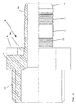
Die in Fig. 1a dargestellte Ausführungsform einer
Rohrverbindung 10 weist einen Bund 12 und eine
Stutzhülse 14 auf. Koaxial zur Stützhülse 14 ist eine
Schraubverbindung 20 vorgesehen, um den erfindungsgemäßen
Rohrverbinder 10 beispielsweise mit einem
Heizkörper oder dergleichen verschrauben zu können.
Der Bund 12 weist einen ringförmigen axial erstreckten
Abschnitt 16 auf, der einen Teil der Stützhülse
14 überdeckt, so daß sich eine umfängliche Ausnehmung
18 ergibt, in die ein nicht dargestelltes Rohr hineingeschoben
werden kann.The embodiment shown in Fig.
Die Stützhülse 14 weist mehrere unterschiedliche
Profilierungen auf. In einem Bereich nahe dem
Bund 12 weist die Stützhülse 14 umfängliche Rillierungen
22 bzw. Grate 24 auf. An diesen Bereich schließt
ein glatter Bereich 26 an. In diesem Bereich kann vorteilhafterweise
auch eine Rändelung vorgesehen werden.The
Jenseits dieses beispielsweise gerändelten
Bereichs 26 schließt entgegengesetzt zur Rohr-Aufschieberichtung
ein weiterer profilierter Abschnitt an, indem
wiederum Vertiefungen 22 und Erhöhungen 24 jeweils
umfänglich vorgesehen sind. An der axialen Stirnfläche
der Stützhülse 14 ist ein zulaufender Bereich 28
vorgesehen, der ein Aufschieben eines Rohres erleichtern
soll.Beyond this knurled, for
Die Erhöhungen bzw. Vertiefungen 22, 24, etwa
umfängliche Rillen und/oder Grate bilden zusammen
mit dem in seiner korrekten Stellung befindlichen,
aufgeschobenen Rohr jeweilige Dichteinrichtungen, die
darüber hinaus in Verbindung mit der verpreßten Stützhülse
(nicht dargestellt) das Rohr an der Stützhülse festlegen.
Die (nicht dargestellte) Preßhülse wird in der Regel
nur in den Bereichen verpreßt, in denen die erläuterten
Profilierungen 22, 24 vorgesehen sind. Durch das
Verpressen wird das Rohrmaterial in die umfänglichen
Profilierungen bzw. Rillierungen 22 hineingepreßt, wodurch
sich der besagte Kraftschluß und die besagte
Dichtwirkung ergeben.The elevations or
Da das über die Preßhülse an der Stützhülse
14 festgelegte Rohr durch die Profilierungen 22, 24 im
wesentlichen nur gegen das Abziehen des Rohres von
der erfindungsgemäßen Rohrverbindung 10 gesichert
ist, ist es von Vorteil, wenn die Rändelung 26 in die
Stützhülse 14 eingearbeitet wird, da über die Rändelung
ein Verdrehen des Rohres nach erfolgter Verpressung
auf der Stützhülse 14 verhindert werden kann, da die
Rändelung eine Kontur aufweist, die im wesentlichen
senkrecht zur Umfangsrichtung verläuft. Besonders
vorteilhaft ist es, wenn die Rändelung so ausgebildet ist,
daß die Spitzen in der Tiefe des Materials liegen bzw.
vergraben sind, da diese Ausbildung dazu beiträgt, daß
eine Undichtigkeit bewirkende Durchflußpfade entlang
des gerändelten Abschnitts 26 entstehen können, wenn
die Rändelung einen Versatz aufweist, d.h. das Rändelungsprofil
beispielsweise um 30° aus der zu der Umfangsrichtung
senkrecht verlaufenden Richtung ausgelenkt
ist, lassen sich Leckagen noch wirksamer vermeiden.Since that on the press sleeve on the
Die aus der Darstellung gemäß Fig. 1 nicht ersichtliche
Ausnehmung bzw. Öffnung oder Öffnungen,
die sowohl während eines Verpreßvorganges als auch
davor und danach eine freie Sicht zumindest auf die
Stirnfläche des Rohres und/oder der Stützhülse zuläßt,
weist in etwa oder vorzugsweise genau in Axialrichtung
der Stützhülse 14 bzw. der Rohrverbindung 10 die gleiche
Abmessung auf, wie der in der gleichen Richtung
erstreckte ringförmige Abschnitt 16.The one that is not apparent from the illustration according to FIG. 1
Recess or opening or openings,
both during a pressing process and
before and after, a clear view at least of the
Front face of the tube and / or the support sleeve,
has approximately or preferably exactly in the axial direction
the
In der Fig. 1 b ist ein mögliches Profil der Stützhülse
14 in einem vergrößerten Maßstab dargestellt.
Die Form der Dicht- bzw. Halteprofile 22, 24 ist aus dieser
Darstellung besonders gut ersichtlich. Die umfänglich
verlaufenden Profile 24 erlauben ein erleichtertes
Aufschieben des Rohres und erschweren das Abziehen
des Rohres. Für die eigentliche Dichtwirkung ist diese
Formgebung wesentlich.In Fig. 1 b is a possible profile of the
In der Fig. 2 ist eine weitere Ausführungsform
einer Rohrverbindung 10' gemäß der Erfindung zu erkennen.
Bei dieser Ausführungsform grenzen an den
Bund 12 auf jeder Seite in Axialrichtung der Rohrverbindung
10' jeweilige Stützhülsen 14 an, wobei die linke
Stutzhülse 14 einen größeren Innen- und Außendurchmesser
hat als die rechte Stützhülse. Auf jeder Seite des
Bundes 12 sind vorzugsweise 180° zueinander versetzte
Ausnehmungen 16a, 16b vorgesehen, die einen freien
Einblick auf die Stirnfläche des aufgeschobenen
Rohres (nicht dargestellt), das an der zugeordneten
Stirnfläche des Bundes 12 anliegt, zulassen. In die sich
ergebende umfängliche Ausnehmung 18 wird das an
der erfindungsgemäßen Rohrverbindung 10' festzulegende
Rohr eingeschoben. Die Profilierung der Stützhülse
14 entspricht in diesem Falle vorzugsweise der
bei der Erörterung der Fig. 1 besprochenen Ausgestaltung.2 shows a further embodiment
a pipe joint 10 'according to the invention.
In this embodiment, the
Die rechts und links der längsschnittlichen
Darstellung wiedergegebenen axialen Draufsichten zeigen
die in dem einstückig ausgebildeten ringförmigen
Abschnitt 16 eingearbeiteten, beispielsweise eingefrästen,
Ausnehmungen bzw. Öffnungen 16a, 16b.The right and left of the longitudinal
Show representation shown axial top views
which in the one-piece
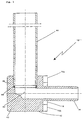
In der Fig. 3 ist ein Knie- bzw. Winkelstück 10°
dargestellt, das mit einer erfindungsgemäß ausgebildeten
Rohrverbindung versehen ist. Der Bund 12 gemäß
der Ausführungsform 10" geht unmittelbar in ein Eck-
bzw. Kniestück 40 über. Dieses Kniestück 40 weist eine
ebenfalls in einem rechten Winkel verlaufende Leitung
42 auf, die einen Anschluß zwischen der Öffnung der
Stützhülse 14 und der Anschlußöffnung ergibt, in die ein
Rohr 44 in einem Rohrsitz 46 eingepaßt ist. In den Rohrsitz
46 ist im vorliegenden Falle eine Lotringeinlage 48
eingelegt, die dazu dient, nach dem Einschieben des
Rohres 44, beispielsweise ein Kupferrohr, Messingrohr
oder dergleichen, weich- oder hartverlötet zu werden.
Natürlich kann hier auch geschweißt, geklebt oder gepreßt
werden.3 is a knee or
In der Fig. 4 ist eine weitere Ausführungsform
10"' der Rohrverbindung gemäß der vorliegenden Erfindung
zu erkennen. Rechts und links von einem sehr
breit ausgeführten Bund 12 sind erfindungsgemäß ausgebildete
Rohrverbindungsabschnitte mit jeweiligen
Stützhülsen 14, ringförmigen, umfänglichen Ausnehmungen
18 und Prüföffnungen bzw. Prüfausnehmungen
16a, 16b zu erkennen. In die Breitseite des relativ
breit ausgeführten Bundes 12 ist eine Anschlußöffnung
62 eingearbeitet, in die ein Anschlußrohr 60 wiederum
beispielsweise über eine Lotringeinlage 64 eingelötet
werden kann. 4 is a
Soll ein Verbindungsvorgang durchgeführt
werden, wird ein Rohr beispielsweise auf die Stützhülse
14 gemäß Fig. 1a aufgeschoben, so daß das Ende des
(nicht dargestellten) Rohres in der umfänglichen Ausnehmung
18 unter dem ringförmigen erstreckten Abschnitt
16 am Bund 12 sitzt. Anschließend wird die
Preßhülse soweit aufgeschoben, daß sie bevorzugt an
der Stirnseite des Abschnittes 16 anliegt. Der korrekte
Sitz des Rohres an der Stirnseite des Bundes 12 kann
über die Öffnungen bzw. Ausnehmen 16a, 16b (siehe
beispielsweise Fig. 2) vor dem Verpressen der Preßhülse
überprüft werden.Should perform a connection process
be a tube, for example, on the
Sind das Rohr und die Preßhülse korrekt angeordnet,
wird eine Preßzange an der Preßhülse angesetzt.
Da der Bund 12 bzw. der Abschnitt 16 in diesem
Stadium für den Blick der Bedienungsperson frei zugängig
sind, kann die Bedienungsperson auch jetzt die Lage
des Rohres und der Preßhülse über die Öffnungen
bzw. Ausnehmungen 16a, 16b prüfen, wobei die umfängliche
Ausnehmung 18 auch in Verbindung mit den
Profilierungen das Rohr in einer optimalen Stellung halten
können. Wird nun die Preßzange betätigt, so beginnt
der Preßvorgang. Dieser Preßvorgang erfordert einen
relativ langen Zeitraum, da die Preßzange über eine Hydraulik,
über eine Gewindespindel oder dergleichen betätigt
wird. Erkennt die Bedienungsperson während der
ersten Augenblicke des Preßvorgangs ein Verrutschen
des Rohres und/oder der Preßhülse, kann der Preßvorgang
abgebrochen werden und die Lage des Rohres
und/oder der Preßhülse können korrigiert werden. Ist
der Preßvorgang fortgeschritten, verändert sich die korrekte
Lage des Rohres und/oder der Preßhülse in der
Regel nicht mehr, so daß eine weitere Beobachtung der
korrekten Lage des Rohres und/oder der Preßhülse
nicht mehr erforderlich wäre.If the pipe and the press sleeve are correctly arranged,
a pair of crimping pliers is attached to the crimp sleeve.
Since the
Claims (8)
- Composite pipe connection arrangement (10, 10', 10", 10"'), for composite pipes with the following features:having at least one connecting region for the pipe,having at least one collar on the connecting region on which the pipe can be set,having at least one support sleeve (14) on the connecting region onto which the pipe can be pushed,with a radially deforming pressable, cylindrical press sleeve in which arrangementthe collar (12) has on its outer periphery at least one recess (16a, 16b) or opening or transparent region or the like, which is or are provided on the edge region of the collar (12) associated with the placement region or connecting region or connecting regions (14) so that the position of a pipe can be checked, in which arrangementthe collar (12) has a section (16) extending parallel to the axis of symmetry of the cylinder and protruding from the end surface of the collar (12), either in the form of a separate annular section or in the form of a section integrally formed with the collar (12), the recess(es) or opening(s) being provided in at least one of the sections, and in which arrangementthe section (16) projecting relative to the press sleeve has a diameter such that the press sleeve is in contact with an end surface of the projecting section.
- Arrangement according to Claim 1, characterized in that the separate annular section is constructed of a transparent material in at least some regions.
- Arrangement according to one of Claims 1 or 2, characterized in that the respective section (16) has an internal diameter which is dimensioned relative to the external diameter of the connection region or the support sleeve (14) in such a way that a pipe to be connected can be pushed into the intermediate space with clearance, preferably tightly.
- Arrangement according to one of Claims 1 to 3, characterized in that the connection region or the support sleeve (14) has peripheral elevations or depressions (22, 24) on a region or on regions at which the press sleeve is pressed onto the connecting region in its pressed position.
- Arrangement according to one of Claims 1 to 4, characterized in that the connecting region or the support sleeve (14) has knurling, preferably with deeper points, at a region (26) or at regions (26) at which the press sleeve is not pressed in its pressed position on the connecting region or the support sleeve (14), the peaks being configured offset relative to one another.
- Arrangement according to one of Claims 1 to 5, characterized in that two recesses or openings (16a, 16b) are peripherally offset relative to one another by 180° or that the press sleeve has an assembly slip prevention device or a slip brake, which may be configured by means of an internal conical or double conical configuration of the press sleeve, which configuration provides a contraction in a central region in the longitudinal direction of the press sleeve or which provides respective contractions at one or both end regions of the press sleeve, these contractions having a slightly smaller internal diameter than the pipe dimensioned to match the press sleeve.
- Arrangement according to Claim 6, characterized in that the slip brake has at least one extension directed radially inwards.
- Arrangement according to one of Claims 1 to 7, characterized in that respective connection regions or support sleeves (14) with the same or different external and/or internal diameters are provided on both sides of the collar (12), it being possible to arrange a knee-piece or a screw connection (20) or the like particularly on one side of the collar (12), and at least one, preferably soldered, pressed-in or welded-in metal pipe (60, 44) is preferably inserted in the longitudinal region or in the side surface of the collar (12) of the pipe connection.
Applications Claiming Priority (2)
| Application Number | Priority Date | Filing Date | Title |
|---|---|---|---|
| DE4441373 | 1994-11-21 | ||
| DE4441373A DE4441373C2 (en) | 1994-11-21 | 1994-11-21 | Pipe connection, in particular for pipes with at least one plastic layer |
Publications (3)
| Publication Number | Publication Date |
|---|---|
| EP0713042A1 EP0713042A1 (en) | 1996-05-22 |
| EP0713042B1 EP0713042B1 (en) | 1999-07-14 |
| EP0713042B2 true EP0713042B2 (en) | 2003-08-20 |
Family
ID=6533754
Family Applications (1)
| Application Number | Title | Priority Date | Filing Date |
|---|---|---|---|
| EP95118296A Expired - Lifetime EP0713042B2 (en) | 1994-11-21 | 1995-11-21 | Connection arrangement for composite pipes |
Country Status (3)
| Country | Link |
|---|---|
| EP (1) | EP0713042B2 (en) |
| AT (1) | ATE182203T1 (en) |
| DE (2) | DE4441373C2 (en) |
Families Citing this family (17)
| Publication number | Priority date | Publication date | Assignee | Title |
|---|---|---|---|---|
| EP0913612B1 (en) | 1997-11-03 | 2003-04-02 | NOVOPRESS GMBH PRESSEN UND PRESSWERKZEUGE & CO. KG. | Procedure for connecting a pipe with a pipe coupling, a coupling between a pipe and a pipe coupling and a pipe coupling therefor |
| DE19749748C1 (en) * | 1997-11-03 | 1999-04-08 | Novopress Gmbh | Joining pipe end to pipe coupling by compression |
| DE19748623B4 (en) * | 1997-11-04 | 2009-06-04 | Henco Industries Nv | compression joint |
| AT2219U1 (en) * | 1997-12-22 | 1998-06-25 | Jaeggi Georg | PRESSABLE PIPE CONNECTION |
| FR2775508B1 (en) | 1998-03-02 | 2000-04-14 | Comap Abbeville | CRIMP CONNECTION FOR PIPE MADE OF SYNTHETIC MATERIAL |
| DE19841801C1 (en) * | 1998-09-12 | 2000-05-04 | Hewing Gmbh | Fitting for a pipe |
| DE19854148A1 (en) * | 1998-11-24 | 2000-11-02 | Friatec Ag | Plug-in coupling |
| DE19935246B4 (en) | 1999-06-04 | 2004-07-22 | Friatec Ag | Connectors |
| DE19932718A1 (en) * | 1999-09-23 | 2001-05-23 | Friatec Ag | Plug-in coupling for connecting two pipe ends; has base body, sealing ring and prestressed locking ring, where pipe end fits in gap between base body and annular body and is sealed with locking ring |
| DE19956000C1 (en) * | 1999-11-20 | 2001-01-25 | Ivt Installations Und Verbindu | Clamp fitting for polymer pipes/hoses has support sleeve with collar at one end forming ring surface towards insertion end with structured ribs to divert surplus and displaced pipe/hose material |
| IT1317144B1 (en) | 2000-03-27 | 2003-05-27 | Giacomini Spa | FITTING FOR FIXING SYNTHETIC MATERIAL TUBES |
| DE10022893C1 (en) | 2000-05-10 | 2001-06-28 | Schuetz Gmbh & Co Kgaa | Compression pipe fitting for plastics connection pipe has spring insulation ring contacted by end of pipe for providing visual indication of correct positioning |
| GB2376510A (en) * | 2001-06-12 | 2002-12-18 | Peter Mcloughlin | Pipe connector with means for visual inspection |
| DE20121354U1 (en) | 2001-07-03 | 2002-12-05 | Polypress Rohrsysteme Gmbh | connecting element |
| DE202005016258U1 (en) | 2005-10-11 | 2005-12-08 | Ipa Produktions- Und Vertriebsges.M.B.H. | Connecting system for plastic and plastic-metal composite pipes comprises supporting sleeve which fits over pipes, press fitting which fits over sleeve and locking ring which fits into groove on sleeve |
| DE102008039991B3 (en) | 2008-08-27 | 2009-10-29 | Kottmann Gosla Gmbh | Pressure hose for use as e.g. pressure-resistant connecting hose, for connecting part of water-guiding system, has inner hose formed by corrugated hose and comprising ring bulges circulating tube-shaped connector |
| DE202009016975U1 (en) | 2009-12-16 | 2011-04-28 | Uponor Innovation Ab | Fitting for a pipe |
Citations (1)
| Publication number | Priority date | Publication date | Assignee | Title |
|---|---|---|---|---|
| US3885819A (en) † | 1972-11-21 | 1975-05-27 | Herbert Egerer | Compressed air hose connection |
Family Cites Families (6)
| Publication number | Priority date | Publication date | Assignee | Title |
|---|---|---|---|---|
| US1926270A (en) * | 1932-08-13 | 1933-09-12 | Eastman Joseph Peter | Pressed-on hose coupling |
| US2177095A (en) * | 1936-02-15 | 1939-10-24 | Cowles Irving | Flexible conduit and coupling therefor and method of making same |
| US5049745A (en) * | 1988-11-14 | 1991-09-17 | Amray, Inc. | Phase-compensating vibration cancellation system for scanning electron microscopes |
| JPH03186683A (en) * | 1989-12-14 | 1991-08-14 | Sekisui Chem Co Ltd | Pipe joint |
| DE9016310U1 (en) | 1990-11-30 | 1991-02-21 | Hewing Gmbh, 4434 Ochtrup, De | |
| DE9110998U1 (en) * | 1991-09-05 | 1991-10-31 | Hewing Gmbh |
-
1994
- 1994-11-21 DE DE4441373A patent/DE4441373C2/en not_active Expired - Lifetime
-
1995
- 1995-11-21 EP EP95118296A patent/EP0713042B2/en not_active Expired - Lifetime
- 1995-11-21 DE DE59506383T patent/DE59506383D1/en not_active Expired - Lifetime
- 1995-11-21 AT AT95118296T patent/ATE182203T1/en active
Patent Citations (1)
| Publication number | Priority date | Publication date | Assignee | Title |
|---|---|---|---|---|
| US3885819A (en) † | 1972-11-21 | 1975-05-27 | Herbert Egerer | Compressed air hose connection |
Also Published As
| Publication number | Publication date |
|---|---|
| DE59506383D1 (en) | 1999-08-19 |
| EP0713042A1 (en) | 1996-05-22 |
| ATE182203T1 (en) | 1999-07-15 |
| EP0713042B1 (en) | 1999-07-14 |
| DE4441373C2 (en) | 1997-12-04 |
| DE4441373A1 (en) | 1996-05-23 |
Similar Documents
| Publication | Publication Date | Title |
|---|---|---|
| EP0713042B2 (en) | Connection arrangement for composite pipes | |
| EP0501404B1 (en) | Connection device for plastic pipes and method for connecting a plastic pipe | |
| DE19631574C1 (en) | Pressed union between pipes | |
| DE102008039446B4 (en) | Arrangement and method for producing a non-detachable workpiece connection | |
| EP2918375B1 (en) | Press jaw, method for producing a non-removable pipe connection, fitting and system consisting of a pressure jaw and a fitting | |
| EP0883771A1 (en) | Pipe connection | |
| EP3596377B1 (en) | Fitting for connecting to at least one pipe and method for producing a connection | |
| DE3246327A1 (en) | Device for connecting two pipe ends | |
| EP0932786B1 (en) | Pipe coupling | |
| DE4135422C2 (en) | Clamp connector for pipes or hoses made of polymer material | |
| DE60115413T2 (en) | FITTING FOR A PRESSURE COUPLING FOR PLASTIC PIPES | |
| DE19929010C1 (en) | Pipe connection has a molded plastics body to hold the pipe connector with a press sleeve and a support sleeve with a free zone to allow a slight bend or tilt in the assembly | |
| DE19813805C1 (en) | Pipe coupling | |
| DE4325349C2 (en) | Connecting device | |
| WO2000012925A1 (en) | Pipe connection | |
| CH682175A5 (en) | Connection for domestic piping - has fitting to which cylindrical protective socket is releasably fixed, socket covering connection onto which one end of union pipe is pushed | |
| DE102006048287B3 (en) | Fitting for a pipe | |
| EP1326045A2 (en) | Connector for at least one pipe part and method for making a connection with such a connector | |
| WO1998019092A1 (en) | Pipe coupling | |
| DE19748937C1 (en) | Pipe connector for metal pipes | |
| DE10331381A1 (en) | Compression connection has support sleeve fitted into pipe end and with encompassing collar bearing on end edge of pipe end and fixed between stop on compressible section and end edge of pipe end | |
| EP3492796B1 (en) | Connection system for repairing plastic composite pipe systems | |
| DE4400283C1 (en) | Connection between metal and plastics pipe | |
| DE10013569C2 (en) | Pipe press connection | |
| DE10156464B4 (en) | fitting |
Legal Events
| Date | Code | Title | Description |
|---|---|---|---|
| PUAI | Public reference made under article 153(3) epc to a published international application that has entered the european phase |
Free format text: ORIGINAL CODE: 0009012 |
|
| AK | Designated contracting states |
Kind code of ref document: A1 Designated state(s): AT BE CH DE FR IT LI LU NL |
|
| 17P | Request for examination filed |
Effective date: 19960402 |
|
| 17Q | First examination report despatched |
Effective date: 19970905 |
|
| GRAG | Despatch of communication of intention to grant |
Free format text: ORIGINAL CODE: EPIDOS AGRA |
|
| GRAG | Despatch of communication of intention to grant |
Free format text: ORIGINAL CODE: EPIDOS AGRA |
|
| GRAH | Despatch of communication of intention to grant a patent |
Free format text: ORIGINAL CODE: EPIDOS IGRA |
|
| RBV | Designated contracting states (corrected) |
Designated state(s): AT BE CH DE FR IT LI LU NL |
|
| GRAH | Despatch of communication of intention to grant a patent |
Free format text: ORIGINAL CODE: EPIDOS IGRA |
|
| GRAA | (expected) grant |
Free format text: ORIGINAL CODE: 0009210 |
|
| AK | Designated contracting states |
Kind code of ref document: B1 Designated state(s): AT BE CH DE FR IT LI LU NL |
|
| REF | Corresponds to: |
Ref document number: 182203 Country of ref document: AT Date of ref document: 19990715 Kind code of ref document: T |
|
| REG | Reference to a national code |
Ref country code: CH Ref legal event code: EP |
|
| REG | Reference to a national code |
Ref country code: CH Ref legal event code: NV Representative=s name: RIEDERER HASLER & PARTNER PATENTANWAELTE AG |
|
| REF | Corresponds to: |
Ref document number: 59506383 Country of ref document: DE Date of ref document: 19990819 |
|
| ET | Fr: translation filed | ||
| PLBQ | Unpublished change to opponent data |
Free format text: ORIGINAL CODE: EPIDOS OPPO |
|
| PLBI | Opposition filed |
Free format text: ORIGINAL CODE: 0009260 |
|
| PLBF | Reply of patent proprietor to notice(s) of opposition |
Free format text: ORIGINAL CODE: EPIDOS OBSO |
|
| 26 | Opposition filed |
Opponent name: IPA PRODUKTIONS- UND VERTRIEBSGESELLSCHAFT M.B.H. Effective date: 20000309 |
|
| NLR1 | Nl: opposition has been filed with the epo |
Opponent name: IPA PRODUKTIONS- UND VERTRIEBSGESELLSCHAFT M.B.H. |
|
| PLBF | Reply of patent proprietor to notice(s) of opposition |
Free format text: ORIGINAL CODE: EPIDOS OBSO |
|
| PLBF | Reply of patent proprietor to notice(s) of opposition |
Free format text: ORIGINAL CODE: EPIDOS OBSO |
|
| PLAW | Interlocutory decision in opposition |
Free format text: ORIGINAL CODE: EPIDOS IDOP |
|
| APAC | Appeal dossier modified |
Free format text: ORIGINAL CODE: EPIDOS NOAPO |
|
| APAE | Appeal reference modified |
Free format text: ORIGINAL CODE: EPIDOS REFNO |
|
| APAC | Appeal dossier modified |
Free format text: ORIGINAL CODE: EPIDOS NOAPO |
|
| APAC | Appeal dossier modified |
Free format text: ORIGINAL CODE: EPIDOS NOAPO |
|
| PLAW | Interlocutory decision in opposition |
Free format text: ORIGINAL CODE: EPIDOS IDOP |
|
| RTI2 | Title (correction) |
Free format text: CONNECTION ARRANGEMENT FOR COMPOSITE PIPES |
|
| PUAH | Patent maintained in amended form |
Free format text: ORIGINAL CODE: 0009272 |
|
| STAA | Information on the status of an ep patent application or granted ep patent |
Free format text: STATUS: PATENT MAINTAINED AS AMENDED |
|
| 27A | Patent maintained in amended form |
Effective date: 20030820 |
|
| AK | Designated contracting states |
Designated state(s): AT BE CH DE FR IT LI LU NL |
|
| REG | Reference to a national code |
Ref country code: CH Ref legal event code: AEN Free format text: AUFRECHTERHALTUNG DES PATENTES IN GEAENDERTER FORM |
|
| NLR2 | Nl: decision of opposition |
Effective date: 20030820 |
|
| NLR3 | Nl: receipt of modified translations in the netherlands language after an opposition procedure | ||
| ET3 | Fr: translation filed ** decision concerning opposition | ||
| APAH | Appeal reference modified |
Free format text: ORIGINAL CODE: EPIDOSCREFNO |
|
| REG | Reference to a national code |
Ref country code: CH Ref legal event code: PCAR Free format text: RIEDERER HASLER & PARTNER PATENTANWAELTE AG;ELESTASTRASSE 8;7310 BAD RAGAZ (CH) |
|
| REG | Reference to a national code |
Ref country code: DE Ref legal event code: R082 Ref document number: 59506383 Country of ref document: DE Representative=s name: WEICKMANN & WEICKMANN PATENT- UND RECHTSANWAEL, DE Ref country code: DE Ref legal event code: R082 Ref document number: 59506383 Country of ref document: DE Representative=s name: WEICKMANN & WEICKMANN PATENTANWAELTE - RECHTSA, DE Ref country code: DE Ref legal event code: R082 Ref document number: 59506383 Country of ref document: DE Representative=s name: PATENTANWAELTE WEICKMANN & WEICKMANN, DE |
|
| PGFP | Annual fee paid to national office [announced via postgrant information from national office to epo] |
Ref country code: LU Payment date: 20141121 Year of fee payment: 20 |
|
| PGFP | Annual fee paid to national office [announced via postgrant information from national office to epo] |
Ref country code: DE Payment date: 20140930 Year of fee payment: 20 Ref country code: CH Payment date: 20141119 Year of fee payment: 20 Ref country code: FR Payment date: 20141119 Year of fee payment: 20 |
|
| PGFP | Annual fee paid to national office [announced via postgrant information from national office to epo] |
Ref country code: AT Payment date: 20141120 Year of fee payment: 20 Ref country code: NL Payment date: 20141119 Year of fee payment: 20 |
|
| PGFP | Annual fee paid to national office [announced via postgrant information from national office to epo] |
Ref country code: IT Payment date: 20141125 Year of fee payment: 20 |
|
| PGFP | Annual fee paid to national office [announced via postgrant information from national office to epo] |
Ref country code: BE Payment date: 20141118 Year of fee payment: 20 |
|
| REG | Reference to a national code |
Ref country code: DE Ref legal event code: R071 Ref document number: 59506383 Country of ref document: DE |
|
| REG | Reference to a national code |
Ref country code: NL Ref legal event code: MK Effective date: 20151120 |
|
| REG | Reference to a national code |
Ref country code: CH Ref legal event code: PL |
|
| REG | Reference to a national code |
Ref country code: AT Ref legal event code: MK07 Ref document number: 182203 Country of ref document: AT Kind code of ref document: T Effective date: 20151121 |