EP0713005B1 - Connection of an ignition coil and a spark plug for internal combustion engine - Google Patents
Connection of an ignition coil and a spark plug for internal combustion engine Download PDFInfo
- Publication number
- EP0713005B1 EP0713005B1 EP95115954A EP95115954A EP0713005B1 EP 0713005 B1 EP0713005 B1 EP 0713005B1 EP 95115954 A EP95115954 A EP 95115954A EP 95115954 A EP95115954 A EP 95115954A EP 0713005 B1 EP0713005 B1 EP 0713005B1
- Authority
- EP
- European Patent Office
- Prior art keywords
- conductive member
- sleeve
- ignition coil
- protrusion
- terminal
- Prior art date
- Legal status (The legal status is an assumption and is not a legal conclusion. Google has not performed a legal analysis and makes no representation as to the accuracy of the status listed.)
- Expired - Lifetime
Links
Images


Classifications
-
- H—ELECTRICITY
- H01—ELECTRIC ELEMENTS
- H01T—SPARK GAPS; OVERVOLTAGE ARRESTERS USING SPARK GAPS; SPARKING PLUGS; CORONA DEVICES; GENERATING IONS TO BE INTRODUCED INTO NON-ENCLOSED GASES
- H01T13/00—Sparking plugs
- H01T13/02—Details
- H01T13/04—Means providing electrical connection to sparking plugs
-
- F—MECHANICAL ENGINEERING; LIGHTING; HEATING; WEAPONS; BLASTING
- F02—COMBUSTION ENGINES; HOT-GAS OR COMBUSTION-PRODUCT ENGINE PLANTS
- F02P—IGNITION, OTHER THAN COMPRESSION IGNITION, FOR INTERNAL-COMBUSTION ENGINES; TESTING OF IGNITION TIMING IN COMPRESSION-IGNITION ENGINES
- F02P3/00—Other installations
- F02P3/02—Other installations having inductive energy storage, e.g. arrangements of induction coils
Definitions
- the present invention relates to an ignition coil assembly for an internal combustion engine for use in connection between a coil portion body of an ignition coil and a spark plug for the internal combustion engine.
- Distributeless ignition systems have been proposed.
- One of the distributorless ignition systems is designed such that a conductor connecting portion directly connects a coil portion body for generating high tension and a spark plug to deliver the high tension from the coil portion body to the spark plug, which is disclosed in, for example, the generic US-A-5,357,233 corresponding to JP-A-5-52175 and from which the present invention starts from or in JP-U-5-30467 or JP-A-5-99112.
- the conductor connecting portion generally comprises a conductive member such as a single spring, a metal round bar and a metal cylinder, and an insulating member for coating the conductive member. There are a variety of processes for positioning the conductive member relative to the insulating member.
- the conductive member is forced into the insulating member formed of a flexible rubber such as silicone rubber in a cylindrical shape.
- the insulating member comprises a sleeve which is a molded resin component, a rubber-made cap and a bushing fitted on opposite ends of the sleeve, and the conductive member is inserted in the sleeve.
- the sleeve and conductive member are formed into a unitary structure.
- the first process might damage the insulating member made of silicone rubber and the like when receiving the conductive member to cause the damaged portion to be thinner, resulting in dielectric breakdown and low reliability. Further, the first process requires a large amount of costly silicone rubber, adding to material costs.
- Forming the sleeve and conductive member into a unitary structure as in the third process adds to fabrication costs because of the single-piece formation.
- Inserting the conductive member in the sleeve as in the second process involves providing a stepped portion in the sleeve and a stepped portion in the conductive member for engaging the stepped portion of the sleeve for positioning the conductive member in the sleeve. In this case, there is a danger of the conductive member slipping off the sleeve unless the conductive member is coupled to parts of the ignition coil.
- an ignition coil assembly for an internal combustion engine comprises: a high-tension terminal and a conductor connecting portion including a conductive member for electrically connecting the high-tension terminal of the ignition coil with a spark plug, and an insulating member, the insulating member including a sleeve for receiving the conductive member, the sleeve being a molded resin component.
- the ignition system furthermore comprises a cylindrical cap made of rubber and fitted on an upper end portion of the sleeve for covering an electrical connecting portion between the high-tension terminal of the ignition coil and an upper end portion of the conductive member, the conductive member having a first protrusion raised outwardly from an upper outer peripheral surface thereof and locked to an upper end surface of the sleeve, the cylindrical cap having a second protrusion on an inner peripheral surface thereof for engaging an upper side of the first protrusion to prevent the conductive member from slipping off.
- the first protrusion is a projection formed on a part of the outer periphery of the conductive member
- the second protrusion is a ledge formed on the inner periphery of the cylindrical cap throughout the entire circumference.
- the first protrusion is a ledge formed on the outer periphery of the conducive member throughout the entire circumference
- the second protrusion is a projection formed on a part of the inner periphery of the cylindrical cap.
- an ignition coil assembly for an internal combustion engine comprises: a high-tension terminal and a conductor connecting portion including a conductive member for electrically connecting the high-tension terminal of the ignition coil with a spark plug, and an insulating member, the insulating member including a sleeve for receiving the conductive member, the sleeve being a molded resin component.
- the ignition system furthermore comprises a cylindrical cap made of rubber and fitted on an upper end portion of the sleeve for covering an electrical connecting portion between the high-tension terminal of the ignition coil and an upper end portion of the conductive member, the conductive member having a protrusion raised outwardly from an upper outer peripheral surface thereof, the cylindrical cap having a recess in an inner peripheral surface thereof for engaging the protrusion to prevent the conductive member from slipping off.
- the protrusion is a projection formed on a part of the outer periphery of the conductive member.
- the protrusion is a ledge formed on the outer periphery of the conductive member throughout the entire circumference.
- an ignition coil assembly for an internal combustion engine comprises: a high-tension terminal and a conductor connecting portion including a conductive member for electrically connecting the high-tension terminal of the ignition coil with a spark plug, and an insulating member, the insulating member including a sleeve for receiving the conductive member, the sleeve being a molded resin component.
- the ignition system furthermore comprises a cylindrical cap made of rubber and fitted on an upper end portion of the sleeve for covering an electrical connecting portion between the high-tension terminal of the ignition coil and an upper end portion of the conductive member, the conductive member including a first stepped portion formed in an upper portion of an outer peripheral surface of the conductive member so that the outer diameter of a lower portion of the first stepped portion is greater than that of an upper portion thereof, and a second stepped portion formed in the outer peripheral surface of the conductive member under the first stepped portion, so that the outer diameter of a lower portion of the second stepped portion is less than that of an upper portion thereof, the sleeve having a third stepped portion formed in an inner peripheral surface thereof for engaging the second stepped portion from below, the cylindrical cap having a fourth stepped portion formed in an inner peripheral surface thereof for engaging the first stepped portion from above.
- the first protrusion, projection or ledge in the upper portion of the conductive member advances beyond the second protrusion, projection or ledge on the rubber-made cap into the position lower than the second protrusion, projection or ledge.
- the upper side of the first protrusion, projection or ledge engages the second protrusion, projection or ledge to prevent the upward movement of the conductive member.
- the lower side of the first protrusion, projection or ledge is locked to the upper end surface of the sleeve to prevent the conductive member from slipping off downwardly. This allows the complete positioning of the conductive member.
- the conductive member when the conductive member is inserted into the sleeve from above the cap, with the cap fitted on the upper portion of the sleeve, then the protrusion, projection or ledge of the conductive member engages the recess of the cap, insuring the positioning of the conductive member in the sleeve.
- the first stepped portion of the conductive member engages the fourth stepped portion of the cap to prevent the upward movement of the conductive member
- the second stepped portion of the conductive member engages the third stepped portion of the sleeve to prevent the conductive member from slipping off downwardly. This allows the complete positioning of the conductive member.
- the ignition coil assembly according to the present invention is designed to position the conducive member by locking or engaging the protrusion, projection, ledge or stepped portions of the conductive member to the upper end surface of the sleeve, the stepped portions in the inner surface of the sleeve, or the protrusion, ledge, projection or recess of the cap. This prevents the complicated shapes of the conductive member and insulating member and achieves fabrication of the mold or die at low costs, thereby reducing the costs of the respective parts.
- the ignition coil assembly may be readily assembled only by inserting the conductive member into the sleeve, achieving good workability and total fabrication cost reduction.
- an ignition system for an internal combustion engine comprises a spark plug 10 mounted in the bottom of a plug hole H formed in a cylinder head C so that a terminal 11 thereof projects upwardly, an ignition coil 20 mounted in an upper portion of the plug hole H by a support member 22 so that a high-tension tower 21 serving as an electrically connecting portion projects downwardly, and a conductor connecting portion 30 for electrical connection between the ignition coil 20 and the spark plug 10.
- the conductor connecting portion 30, as shown in Figs. 1 to 5, comprises a conductive member 40 including a cylindrical terminal 41 having an upper end fitted in the high-tension tower 21 of the ignition coil 20 and a coil spring 46 having an upper end portion inserted in the lower end portion of the terminal 41 and a lower end portion abutting against the top of the terminal 11 of the spark plug 10 when compressed, and an insulating member 50 for covering the conductive member 40.
- the terminal 41 is a cylinder made of a conductive metal having an outer diameter slightly smaller than the inner diameter of a sleeve 55 to be described later, with a resilient C-ring 43 in its upper end portion.
- the C-ring 43 has a pair of inward projections 43a on opposite ends of the inner surface thereof, and is mounted on the terminal 41 by inserting the projections 43a into through holes (not shown) in the upper end portion of the terminal 41.
- the projections 43a project from the inner surface of the terminal 41 and engage a high-tension terminal (not shown) projecting downwardly in the high-tension tower 21 of the ignition coil 20 when the high-tension terminal is inserted into the terminal 41 from above the terminal 41, thereby establishing electrical and mechanical connections between the terminal 41 and the high-tension terminal.
- the terminal 41 includes, in its lower portion, contact portions 44 for the coil spring 46 which are formed by partially cutting and raising up an outer peripheral surface thereof inwardly, and a inward projection 45 under the contact portions 44.
- the terminal 41 includes, in its upper portion, a ledge 42 under the C-ring 43 and projecting outwardly throughout the entire circumference.
- the ledge 42 has an outer diameter greater than the inner diameter of the sleeve 55 and is locked to the upper end surface of the sleeve 55 to restrict the downward movement of the terminal 41.
- the insulating member 50 comprises a cap 51 made of silicone rubber for covering a range from the high-tension tower 21 to the upper portion of the terminal 41 connected to the high-tension terminal of the high-tension tower 21, a sleeve 55 molded with resin for covering a range from the upper portion of the terminal 41 to a portion of the terminal 11 of the spark plug 10, and a bushing 56 made of silicone rubber for covering the inner and outer surfaces of the lower portion of the sleeve 55.
- the cap 51 is a cylindrical member including a high-tension tower receiving portion 51a for receiving the high-tension tower 21 of the ignition coil 20, and a sleeve receiving portion 51b formed in continuation to the high-tension tower receiving portion 51a for receiving the upper portion of the sleeve 55, with a collar portion 51c extending radially outwardly from the top end of the high-tension tower receiving portion 51a and a bump portion 51d on the outer peripheral surface of the high-tension tower receiving portion 51a.
- the collar portion 51c is locked to the upper surface of the cylinder head C on the periphery of the plug hole H and the bump portion 51d comes in intimate contact with the inner surface of the plug hole H.
- a ledge 52 is formed on the inner peripheral surface of the high-tension tower receiving portion 51a throughout the enter circumference and is adapted to fit in and contact a groove 21a formed in the outer peripheral surface of the high-tension tower 21 when the high-tension tower 21 is inserted in the cap 51.
- a ledge 53 is formed under the ledge 52 on the inner peripheral surface of the sleeve receiving portion 51b throughout the entire circumference and engages the ledge 42 of the terminal 41 from above.
- the ledge 42 in the upper portion of the terminal 41 advances beyond the ledge 53 of the rubber-made cap 51 into the position lower than the ledge 53.
- the upper side of the ledge 42 engages the ledge 53 to prevent the upward movement of the terminal 41, and the lower side of the ledge 42 is locked to the upper end surface of the sleeve 55 to prevent the downward withdrawal of the terminal 41, thereby completely positioning the terminal 41.
- the sleeve receiving portion 51b has two ledges 54 formed on the inner peripheral surface thereof for engaging two grooves 55c formed in the upper outer peripheral surface of the sleeve 55 throughout the entire circumference to provide high sealing performance between the sleeve 55 and the cap 51.
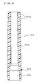
- the sleeve 55 is a cylindrical molded resin component including a conductive member receiving portion 55a for receiving the conductive member 40, and a terminal receiving portion 55b formed in continuation to the conductive member receiving portion 55a for receiving the terminal 11 of the spark plug 10, with the above stated grooves 55c in the upper outer peripheral surface thereof and a ledge 55d on the lower outer peripheral surface thereof throughout the entire circumference.
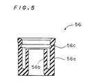
- the bushing 56 is mounted to the terminal receiving portion 55b of the sleeve 55 and includes an outer cylindrical portion 56a for covering the lower outer surface of the terminal receiving portion 55b of the sleeve 55, and an inner cylindrical portion 56b connected to the lower end portion of the outer cylindrical portion 56a for covering the lower inner surface of the terminal receiving portion 55b.
- a groove 56c is formed in the inner peripheral surface of the outer cylindrical portion 56a to receive the ledge 55d of the sleeve 55.
- the bushing 56 is made of flexible silicone rubber as above noted.
- the inner cylindrical portion 56b of silicone rubber comes in intimate contact with the outer peripheral surface of the terminal 11, imparting a waterproofing property.
- the ledges 42 and 53 are formed on the terminal 41 and cap 51, respectively, to position the terminal 41, but the present invention is not limited thereto.
- the terminal 41 may have a projection in place of the ledge 42.
- the cap 51 may have a projection in place of the ledge 53.
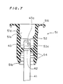
- FIGs. 6 and 7 illustrate a second preferred embodiment according to the present invention.
- An ignition system 2 for an internal combustion engine is generally similar in construction to the ignition system 1. Therefore, like reference numerals and characters are used to designate parts identical with those of the first preferred embodiment, and the description thereof will be dispensed with. Only the differences between the ignition systems 1 and 2 are described below.
- the ignition system 2 differs from the ignition system 1 in the cap 51. Specifically, the terminal 41 of the ignition system 1 is positioned by locking the ledge 42 of the terminal 41 to the upper end surface of the sleeve 55 and pressing the ledge 42 by the ledge 53 of the cap 51 from above.
- the ignition system 2 comprises a groove 53a for receiving the ledge 42 of the terminal 41 in place of the ledge 53 of the cap 51.
- the groove 53a of the cap 51 receives the ledge 42 of the terminal 41, insuring the positioning of the terminal 41 in the sleeve 55.
- the ledge 42 to be fitted in the groove 53a is formed on the terminal 41 to position the terminal 41, but the present invention is not limited thereto.
- the ledge 42 may be replaced with a projection to be fitted in the groove 53a.
- Fig. 8 illustrates a third preferred embodiment according to the present invention.
- An ignition system for an internal combustion engine according to the third preferred embodiment differs from the ignition system 1 in the terminal 41, cap 51 and sleeve 55, which will be described below.
- the terminal 41 includes a large-diameter portion 41a under the C-ring 43 to form a first stepped portion 42a and a second stepped portion 47.
- the sleeve 55 has a third stepped portion 55e for engaging the second stepped portion 47.
- the cap 51 has a fourth stepped portion 53b for engaging the first stepped portion 42a.
- the terminal 41 When the terminal 41 is inserted into the sleeve 55 from above the cap 51, with the upper portion of the sleeve 55 fitted in the sleeve receiving portion 51b of the cap 51, then the first stepped portion 42a of the terminal 41 comes into engagement with the fourth stepped portion 53b of the cap 51 to prevent the upward movement of the terminal 41, and the second stepped portion 47 of the terminal 41 comes into engagement with the third stepped portion 55e of the sleeve 55 to prevent the downward withdrawal of the terminal 41, thereby completely positioning the terminal 41.
Description
- The present invention relates to an ignition coil assembly for an internal combustion engine for use in connection between a coil portion body of an ignition coil and a spark plug for the internal combustion engine.
- Distribution of high tension to each spark plug by a distributor is disadvantageous due to wear of a distributing portion including a distributor cap and a distributor rotor arm and due to electrical noises from the distributing portion. To prevent such disadvantages, distributorless ignition systems have been proposed. One of the distributorless ignition systems is designed such that a conductor connecting portion directly connects a coil portion body for generating high tension and a spark plug to deliver the high tension from the coil portion body to the spark plug, which is disclosed in, for example, the generic US-A-5,357,233 corresponding to JP-A-5-52175 and from which the present invention starts from or in JP-U-5-30467 or JP-A-5-99112.
- The conductor connecting portion generally comprises a conductive member such as a single spring, a metal round bar and a metal cylinder, and an insulating member for coating the conductive member. There are a variety of processes for positioning the conductive member relative to the insulating member.
- For example, the conductive member is forced into the insulating member formed of a flexible rubber such as silicone rubber in a cylindrical shape.
- In another process, the insulating member comprises a sleeve which is a molded resin component, a rubber-made cap and a bushing fitted on opposite ends of the sleeve, and the conductive member is inserted in the sleeve.
- In a further process the sleeve and conductive member are formed into a unitary structure.
- However, the first process might damage the insulating member made of silicone rubber and the like when receiving the conductive member to cause the damaged portion to be thinner, resulting in dielectric breakdown and low reliability. Further, the first process requires a large amount of costly silicone rubber, adding to material costs.
- Forming the sleeve and conductive member into a unitary structure as in the third process adds to fabrication costs because of the single-piece formation.
- Inserting the conductive member in the sleeve as in the second process involves providing a stepped portion in the sleeve and a stepped portion in the conductive member for engaging the stepped portion of the sleeve for positioning the conductive member in the sleeve. In this case, there is a danger of the conductive member slipping off the sleeve unless the conductive member is coupled to parts of the ignition coil.
- It is thus an object of the present invention to provide an ignition coil assembly for an internal combustion engine which has an improved structure for positioning a conductive member inserted in a sleeve and is of good assembly workability with a simple construction to ensure the positioning of the conductive member.
- Solution of this object is achieved by what is claimed in claim 1 or 4 or 7, respectively, whereas the respective subclaims contain preferred and advantageous modifications.
- According to a first aspect of the present invention, an ignition coil assembly for an internal combustion engine comprises: a high-tension terminal and a conductor connecting portion including a conductive member for electrically connecting the high-tension terminal of the ignition coil with a spark plug, and an insulating member, the insulating member including a sleeve for receiving the conductive member, the sleeve being a molded resin component. The ignition system furthermore comprises a cylindrical cap made of rubber and fitted on an upper end portion of the sleeve for covering an electrical connecting portion between the high-tension terminal of the ignition coil and an upper end portion of the conductive member, the conductive member having a first protrusion raised outwardly from an upper outer peripheral surface thereof and locked to an upper end surface of the sleeve, the cylindrical cap having a second protrusion on an inner peripheral surface thereof for engaging an upper side of the first protrusion to prevent the conductive member from slipping off.
- Preferably, the first protrusion is a projection formed on a part of the outer periphery of the conductive member, and the second protrusion is a ledge formed on the inner periphery of the cylindrical cap throughout the entire circumference.
- Also preferably, the first protrusion is a ledge formed on the outer periphery of the conducive member throughout the entire circumference, and the second protrusion is a projection formed on a part of the inner periphery of the cylindrical cap.
- According to a second aspect of the present invention, an ignition coil assembly for an internal combustion engine comprises: a high-tension terminal and a conductor connecting portion including a conductive member for electrically connecting the high-tension terminal of the ignition coil with a spark plug, and an insulating member, the insulating member including a sleeve for receiving the conductive member, the sleeve being a molded resin component. The ignition system furthermore comprises a cylindrical cap made of rubber and fitted on an upper end portion of the sleeve for covering an electrical connecting portion between the high-tension terminal of the ignition coil and an upper end portion of the conductive member, the conductive member having a protrusion raised outwardly from an upper outer peripheral surface thereof, the cylindrical cap having a recess in an inner peripheral surface thereof for engaging the protrusion to prevent the conductive member from slipping off.
- Preferably, the protrusion is a projection formed on a part of the outer periphery of the conductive member.
- Also preferably, the protrusion is a ledge formed on the outer periphery of the conductive member throughout the entire circumference.
- According to a third aspect of the present invention, an ignition coil assembly for an internal combustion engine comprises: a high-tension terminal and a conductor connecting portion including a conductive member for electrically connecting the high-tension terminal of the ignition coil with a spark plug, and an insulating member, the insulating member including a sleeve for receiving the conductive member, the sleeve being a molded resin component. The ignition system furthermore comprises a cylindrical cap made of rubber and fitted on an upper end portion of the sleeve for covering an electrical connecting portion between the high-tension terminal of the ignition coil and an upper end portion of the conductive member, the conductive member including a first stepped portion formed in an upper portion of an outer peripheral surface of the conductive member so that the outer diameter of a lower portion of the first stepped portion is greater than that of an upper portion thereof, and a second stepped portion formed in the outer peripheral surface of the conductive member under the first stepped portion, so that the outer diameter of a lower portion of the second stepped portion is less than that of an upper portion thereof, the sleeve having a third stepped portion formed in an inner peripheral surface thereof for engaging the second stepped portion from below, the cylindrical cap having a fourth stepped portion formed in an inner peripheral surface thereof for engaging the first stepped portion from above.
- In the ignition coil assembly according to the first aspect of the present invention, when the conductive member is inserted into the sleeve from above the cap, with the cap fitted on the upper portion of the sleeve, then the first protrusion, projection or ledge in the upper portion of the conductive member advances beyond the second protrusion, projection or ledge on the rubber-made cap into the position lower than the second protrusion, projection or ledge. The upper side of the first protrusion, projection or ledge engages the second protrusion, projection or ledge to prevent the upward movement of the conductive member. The lower side of the first protrusion, projection or ledge is locked to the upper end surface of the sleeve to prevent the conductive member from slipping off downwardly. This allows the complete positioning of the conductive member.
- In the ignition coil assembly according to the second aspect of the present invention, when the conductive member is inserted into the sleeve from above the cap, with the cap fitted on the upper portion of the sleeve, then the protrusion, projection or ledge of the conductive member engages the recess of the cap, insuring the positioning of the conductive member in the sleeve.
- In the ignition coil assembly according to the third aspect of the present invention, when the conductive member is inserted into the sleeve from above the cap, with the cap fitted on the upper portion of the sleeve, then the first stepped portion of the conductive member engages the fourth stepped portion of the cap to prevent the upward movement of the conductive member, and the second stepped portion of the conductive member engages the third stepped portion of the sleeve to prevent the conductive member from slipping off downwardly. This allows the complete positioning of the conductive member.
- In this manner, the ignition coil assembly according to the present invention is designed to position the conducive member by locking or engaging the protrusion, projection, ledge or stepped portions of the conductive member to the upper end surface of the sleeve, the stepped portions in the inner surface of the sleeve, or the protrusion, ledge, projection or recess of the cap. This prevents the complicated shapes of the conductive member and insulating member and achieves fabrication of the mold or die at low costs, thereby reducing the costs of the respective parts.
- Additionally, there is no need to form the sleeve and the conductive member into a unitary structure. The ignition coil assembly may be readily assembled only by inserting the conductive member into the sleeve, achieving good workability and total fabrication cost reduction.
- These and other features, aspects and advantages of the present invention will become more apparent from the following detailed description of the present invention when taken in conjunction with the accompanying drawings, in which:
- Fig. 1 is a fragmentary cross-sectional view of a first preferred embodiment according to the present invention;
- Fig. 2 is a side view of a terminal of the first preferred embodiment;
- Fig. 3 is a cross-sectional view of a cap of the first preferred embodiment;
- Fig. 4 is a cross-sectional view of a sleeve of the first preferred embodiment;
- Fig. 5 is a cross-sectional view of a bushing of the first preferred embodiment;
- Fig. 6 is a fragmentary cross-sectional view of a second preferred embodiment according to the present invention;
- Fig. 7 is a cross-sectional view of a terminal, when positioned, of the second preferred embodiment; and
- Fig. 8 is a fragmentary cross-sectional view of a third preferred embodiment according to the present invention.
-
- Preferred embodiments according to the present invention will now be described with reference to the drawings. Referring to Fig. 1, an ignition system for an internal combustion engine comprises a
spark plug 10 mounted in the bottom of a plug hole H formed in a cylinder head C so that aterminal 11 thereof projects upwardly, anignition coil 20 mounted in an upper portion of the plug hole H by asupport member 22 so that a high-tension tower 21 serving as an electrically connecting portion projects downwardly, and aconductor connecting portion 30 for electrical connection between theignition coil 20 and thespark plug 10. - The
conductor connecting portion 30, as shown in Figs. 1 to 5, comprises aconductive member 40 including acylindrical terminal 41 having an upper end fitted in the high-tension tower 21 of theignition coil 20 and acoil spring 46 having an upper end portion inserted in the lower end portion of theterminal 41 and a lower end portion abutting against the top of theterminal 11 of thespark plug 10 when compressed, and aninsulating member 50 for covering theconductive member 40. - Referring to Figs. 1 and 2, the
terminal 41 is a cylinder made of a conductive metal having an outer diameter slightly smaller than the inner diameter of asleeve 55 to be described later, with a resilient C-ring 43 in its upper end portion. The C-ring 43 has a pair ofinward projections 43a on opposite ends of the inner surface thereof, and is mounted on theterminal 41 by inserting theprojections 43a into through holes (not shown) in the upper end portion of theterminal 41. With the C-ring 43 mounted on theterminal 41, theprojections 43a project from the inner surface of theterminal 41 and engage a high-tension terminal (not shown) projecting downwardly in the high-tension tower 21 of theignition coil 20 when the high-tension terminal is inserted into theterminal 41 from above theterminal 41, thereby establishing electrical and mechanical connections between theterminal 41 and the high-tension terminal. - The
terminal 41 includes, in its lower portion,contact portions 44 for thecoil spring 46 which are formed by partially cutting and raising up an outer peripheral surface thereof inwardly, and ainward projection 45 under thecontact portions 44. When thecoil spring 46 is inserted into theterminal 41 from below theterminal 41, the top end of thecoil spring 46 abuts against thecontact portions 44 and theprojection 45 fits in the upper side of thecoil spring 46 to electrically connect theterminal 41 and coilspring 46 and support thecoil spring 46 by theterminal 41. - The
terminal 41 includes, in its upper portion, aledge 42 under the C-ring 43 and projecting outwardly throughout the entire circumference. Theledge 42 has an outer diameter greater than the inner diameter of thesleeve 55 and is locked to the upper end surface of thesleeve 55 to restrict the downward movement of theterminal 41. - The
insulating member 50 comprises acap 51 made of silicone rubber for covering a range from the high-tension tower 21 to the upper portion of theterminal 41 connected to the high-tension terminal of the high-tension tower 21, asleeve 55 molded with resin for covering a range from the upper portion of theterminal 41 to a portion of theterminal 11 of thespark plug 10, and abushing 56 made of silicone rubber for covering the inner and outer surfaces of the lower portion of thesleeve 55. - Referring to Figs. 1 and 3, the
cap 51 is a cylindrical member including a high-tensiontower receiving portion 51a for receiving the high-tension tower 21 of theignition coil 20, and asleeve receiving portion 51b formed in continuation to the high-tensiontower receiving portion 51a for receiving the upper portion of thesleeve 55, with acollar portion 51c extending radially outwardly from the top end of the high-tensiontower receiving portion 51a and abump portion 51d on the outer peripheral surface of the high-tensiontower receiving portion 51a. - When the
cap 51 is inserted into the plug hole H from the side of thesleeve receiving portion 51b, thecollar portion 51c is locked to the upper surface of the cylinder head C on the periphery of the plug hole H and thebump portion 51d comes in intimate contact with the inner surface of the plug hole H. - A
ledge 52 is formed on the inner peripheral surface of the high-tensiontower receiving portion 51a throughout the enter circumference and is adapted to fit in and contact agroove 21a formed in the outer peripheral surface of the high-tension tower 21 when the high-tension tower 21 is inserted in thecap 51. Aledge 53 is formed under theledge 52 on the inner peripheral surface of thesleeve receiving portion 51b throughout the entire circumference and engages theledge 42 of theterminal 41 from above. - When the
terminal 41 is inserted into thesleeve 55 from above thecap 51, with the upper portion of thesleeve 55 fitted in thesleeve receiving portion 51b of thecap 51, then theledge 42 in the upper portion of theterminal 41 advances beyond theledge 53 of the rubber-madecap 51 into the position lower than theledge 53. The upper side of theledge 42 engages theledge 53 to prevent the upward movement of theterminal 41, and the lower side of theledge 42 is locked to the upper end surface of thesleeve 55 to prevent the downward withdrawal of theterminal 41, thereby completely positioning theterminal 41. - The
sleeve receiving portion 51b has twoledges 54 formed on the inner peripheral surface thereof for engaging twogrooves 55c formed in the upper outer peripheral surface of thesleeve 55 throughout the entire circumference to provide high sealing performance between thesleeve 55 and thecap 51. - As illustrated in Figs. 1 and 4, the
sleeve 55 is a cylindrical molded resin component including a conductivemember receiving portion 55a for receiving theconductive member 40, and a terminal receivingportion 55b formed in continuation to the conductivemember receiving portion 55a for receiving theterminal 11 of thespark plug 10, with the above statedgrooves 55c in the upper outer peripheral surface thereof and aledge 55d on the lower outer peripheral surface thereof throughout the entire circumference. - With reference to Figs. 1 and 5, the
bushing 56 is mounted to theterminal receiving portion 55b of thesleeve 55 and includes an outercylindrical portion 56a for covering the lower outer surface of theterminal receiving portion 55b of thesleeve 55, and an innercylindrical portion 56b connected to the lower end portion of the outercylindrical portion 56a for covering the lower inner surface of theterminal receiving portion 55b. Agroove 56c is formed in the inner peripheral surface of the outercylindrical portion 56a to receive theledge 55d of thesleeve 55. - When the
terminal receiving portion 55b in the lower portion of thesleeve 55 is inserted into the spacing defined by the outercylindrical portion 56a and innercylindrical potion 56b, theledge 55b is fitted in thegroove 56c, and thebusing 56 is mounted to thesleeve 55. - The
bushing 56 is made of flexible silicone rubber as above noted. Thus, when the terminal 11 of thespark plug 10 is inserted into thesleeve 55 to which thebushing 56 is mounted, the innercylindrical portion 56b of silicone rubber comes in intimate contact with the outer peripheral surface of the terminal 11, imparting a waterproofing property. - In the first preferred embodiment, the
ledges cap 51, respectively, to position the terminal 41, but the present invention is not limited thereto. For example, the terminal 41 may have a projection in place of theledge 42. On the other hand, thecap 51 may have a projection in place of theledge 53. - Figs. 6 and 7 illustrate a second preferred embodiment according to the present invention. An
ignition system 2 for an internal combustion engine is generally similar in construction to the ignition system 1. Therefore, like reference numerals and characters are used to designate parts identical with those of the first preferred embodiment, and the description thereof will be dispensed with. Only the differences between theignition systems 1 and 2 are described below. - The
ignition system 2 differs from the ignition system 1 in thecap 51. Specifically, theterminal 41 of the ignition system 1 is positioned by locking theledge 42 of the terminal 41 to the upper end surface of thesleeve 55 and pressing theledge 42 by theledge 53 of thecap 51 from above. Theignition system 2 comprises agroove 53a for receiving theledge 42 of the terminal 41 in place of theledge 53 of thecap 51. - When the terminal 41 is inserted into the
sleeve 55 from above thecap 51, with the upper portion of thesleeve 55 fitted in thesleeve receiving portion 51b of thecap 51, then thegroove 53a of thecap 51 receives theledge 42 of the terminal 41, insuring the positioning of the terminal 41 in thesleeve 55. - In the second preferred embodiment, the
ledge 42 to be fitted in thegroove 53a is formed on the terminal 41 to position the terminal 41, but the present invention is not limited thereto. For example, theledge 42 may be replaced with a projection to be fitted in thegroove 53a. - Fig. 8 illustrates a third preferred embodiment according to the present invention. An ignition system for an internal combustion engine according to the third preferred embodiment differs from the ignition system 1 in the terminal 41,
cap 51 andsleeve 55, which will be described below. - The terminal 41 includes a large-
diameter portion 41a under the C-ring 43 to form a first stepped portion 42a and a second steppedportion 47. Thesleeve 55 has a third steppedportion 55e for engaging the second steppedportion 47. Thecap 51 has a fourth steppedportion 53b for engaging the first stepped portion 42a. - When the terminal 41 is inserted into the
sleeve 55 from above thecap 51, with the upper portion of thesleeve 55 fitted in thesleeve receiving portion 51b of thecap 51, then the first stepped portion 42a of the terminal 41 comes into engagement with the fourth steppedportion 53b of thecap 51 to prevent the upward movement of the terminal 41, and the second steppedportion 47 of the terminal 41 comes into engagement with the third steppedportion 55e of thesleeve 55 to prevent the downward withdrawal of the terminal 41, thereby completely positioning theterminal 41. - While the invention has been described in detail, the foregoing description is in all aspects illustrative and not restrictive. It is understood that numerous other modifications and variations can be devised without departing from the scope of the invention.
Claims (7)
- An ignition coil assembly for an internal combustion engine comprising:characterized byan ignition coil (20) having a high-tension terminal (21), a conductor connecting portion (30) including a conductive member (40, 41) for electrically connecting the high-tension terminal (21) of the ignition coil (20) with a spark plug (10), andan insulating member (50), said insulating member (50) including a sleeve (55) for receiving said conductive member (40, 41), said sleeve (55) being--a molded resin component,a cylindrical cap (51) made of rubber and fitted on an upper end portion of said sleeve (55) for covering an electrical connecting portion between the high-tension terminal (21) of said ignition coil (20) and an upper end portion of said conductive member (40, 41), said conductive member (40, 41) having a first protrusion (42) raised outwardly from an upper outer peripheral surface thereof and locked to an upper end surface of said sleeve (55), said cylindrical cap (51) having a second protrusion (53) on an inner peripheral surface thereof for engaging an upper side of said first protrusion to (42) prevent said conductive member (40, 41) from slipping off.
- The ignition coil assembly of claim 1, wherein said first protrusion (42) is a projection formed on a part of the outer periphery of said conductive member (40, 41), and wherein said second protrusion (53) is a ledge formed on the inner periphery of said cylindrical cap (51) throughout the entire circumference.
- The ignition coil assembly of claim 1, wherein said first protrusion (42) is a ledge formed on the outer periphery of said conductive member (40, 41) throughout the entire circumference, and wherein said second protrusion (53) is a projection formed on a part of the inner periphery of said cylindrical cap (51).
- An ignition coil assembly for an internal combustion engine comprising:characterized byan ignition coil (20) having a high-tension terminal (21), a conductor connecting portion (30) including a conductive member (40, 41) for electrically connecting the high-tension terminal (21) of the ignition coil (20) with a spark plug (10), andan insulating member (50), said insulating member (50) including a sleeve (55) for receiving said conductive member (40, 41), said sleeve (55) being a molded resin component,a cylindrical cap (51) made of rubber and fitted on an upper end portion of said sleeve (55) for covering an electrical connecting portion between the high-tension terminal (21) of said ignition coil (20) and an upper end portion of said conductive member (40, 41), said conductive member (40, 41) having a protrusion (42) raised outwardly from an upper outer peripheral surface thereof, said cylindrical cap (51) having a recess (53a) in an inner peripheral surface thereof for engaging said protrusion (42) to prevent said conductive member (40, 41) from slipping off.
- The ignition coil assembly of claim 4, wherein said protrusion (42) is a projection formed on a part of the outer periphery of said conductive member (40, 41).
- The ignition coil assembly of claim 4, wherein said protrusion (42) is a ledge formed on the outer periphery of said conductive member (40, 41) throughout the entire circumference.
- An ignition coil assembly for an internal combustion engine comprising:characterized byan ignition coil (20) having a high-tension terminal (21), a conductor connecting portion (30) including a conductive member (40, 41) for electrically connecting the high-tension terminal (21) of the ignition coil (20) with a spark plug (10), andan insulating member (50), said insulating member (50) including a sleeve (55) for receiving said conductive member (40, 41), said sleeve (55) being a molded resin component,a cylindrical cap (51) made of rubber and fitted on an upper end portion of said sleeve (55) for covering an electrical connecting portion between the high-tension terminal (21) of said ignition coil (20) and an upper end portion of said conductive member (40, 41), said conductive member (40, 41) including a first stepped portion (42a) formed in an upper portion of an outer peripheral surface of said conductive member (40, 41) so that the outer diameter of a lower portion of said first stepped portion (42a) is greater than that of an upper portion thereof, and a second stepped portion (47) formed in the outer peripheral surface of said conductive member (40, 41) under said first stepped portion (42a) so that the outer diameter of a lower portion of said second stepped portion (47) is less than that of an upper portion thereof, said sleeve (55) having a third stepped portion (55e) formed in an inner peripheral surface thereof for engaging said second stepped portion (47) from below, said cylindrical cap (51) having a fourth stepped portion (53b) formed in an inner peripheral surface thereof for engaging said first stepped portion (42a) from above.
Applications Claiming Priority (3)
| Application Number | Priority Date | Filing Date | Title |
|---|---|---|---|
| JP6283090A JPH08144918A (en) | 1994-11-17 | 1994-11-17 | Igniter for internal combustion engine |
| JP28309094 | 1994-11-17 | ||
| JP283090/94 | 1994-11-17 |
Publications (3)
| Publication Number | Publication Date |
|---|---|
| EP0713005A2 EP0713005A2 (en) | 1996-05-22 |
| EP0713005A3 EP0713005A3 (en) | 1997-07-30 |
| EP0713005B1 true EP0713005B1 (en) | 2000-02-02 |
Family
ID=17661093
Family Applications (1)
| Application Number | Title | Priority Date | Filing Date |
|---|---|---|---|
| EP95115954A Expired - Lifetime EP0713005B1 (en) | 1994-11-17 | 1995-10-10 | Connection of an ignition coil and a spark plug for internal combustion engine |
Country Status (5)
| Country | Link |
|---|---|
| US (1) | US5537983A (en) |
| EP (1) | EP0713005B1 (en) |
| JP (1) | JPH08144918A (en) |
| CN (1) | CN1044025C (en) |
| DE (1) | DE69514891T2 (en) |
Cited By (1)
| Publication number | Priority date | Publication date | Assignee | Title |
|---|---|---|---|---|
| CN105186291A (en) * | 2015-10-02 | 2015-12-23 | 李军 | Tubular spark plug ignition system of engine and technological method thereof |
Families Citing this family (28)
| Publication number | Priority date | Publication date | Assignee | Title |
|---|---|---|---|---|
| JP3092783B2 (en) * | 1995-05-12 | 2000-09-25 | 矢崎総業株式会社 | Spark plug cap |
| JP3308145B2 (en) * | 1995-12-06 | 2002-07-29 | 株式会社デンソー | Ignition coil for internal combustion engine |
| DE29614872U1 (en) * | 1996-08-27 | 1998-01-02 | Bosch Gmbh Robert | Ignition coil arrangement for internal combustion engines |
| EP0827165B1 (en) * | 1996-08-31 | 2001-06-13 | Toyo Denso Kabushiki Kaisha | Engine igniting coil device |
| US5842458A (en) * | 1997-08-12 | 1998-12-01 | Cummins Engine Company, Inc. | Spark plug boot with ventable seal |
| US5944002A (en) * | 1998-04-17 | 1999-08-31 | Cummins Engine Company, Inc. | Self-venting grommet for coil-on-plug |
| DE19831196C2 (en) * | 1998-07-11 | 2002-06-13 | Audi Ag | Ignition coil unit for internal combustion engines |
| JP3456152B2 (en) * | 1998-10-22 | 2003-10-14 | 株式会社デンソー | Ignition coil |
| DE19852295A1 (en) * | 1998-11-12 | 2000-05-18 | Bayerische Motoren Werke Ag | Ignition system for an internal combustion engine |
| DE19857484C2 (en) | 1998-12-14 | 2002-04-18 | Daimler Chrysler Ag | Connection plug, in particular for ignition systems of motor vehicles |
| US6135099A (en) * | 1999-02-26 | 2000-10-24 | Thomas C. Marrs | Ignition system for an internal combustion engine |
| US6112730A (en) * | 1999-02-26 | 2000-09-05 | Thomas C. Marrs | Ignition system with clamping circuit for use in an internal combustion engine |
| DE10152085A1 (en) | 2001-10-23 | 2003-04-30 | Bosch Gmbh Robert | Lanyards for ignition systems of internal combustion engines |
| EP1560232B1 (en) * | 2004-01-27 | 2012-03-14 | Robert Bosch Gmbh | Ignition coil tester |
| US7129705B1 (en) | 2005-11-17 | 2006-10-31 | M. Eagles Warehouse, Inc. | Ignition spark tester |
| JP4311412B2 (en) * | 2006-04-11 | 2009-08-12 | 三菱電機株式会社 | Ignition coil device |
| JP4741417B2 (en) * | 2006-05-18 | 2011-08-03 | ハスクバーナ・ゼノア株式会社 | Cable terminal and cable using the same |
| US7445001B2 (en) * | 2006-06-15 | 2008-11-04 | Group Dekko Inc | Coil-on-plug ignition terminal |
| US8049399B2 (en) * | 2006-07-21 | 2011-11-01 | Enerpulse, Inc. | High power discharge fuel ignitor |
| US20080276918A1 (en) * | 2007-05-11 | 2008-11-13 | Skinner Albert A | Integrated ignition coil and oil seal for head and cam cover |
| JP5075735B2 (en) * | 2008-05-22 | 2012-11-21 | 日立オートモティブシステムズ阪神株式会社 | Ignition coil for internal combustion engine |
| US8164241B2 (en) * | 2008-08-15 | 2012-04-24 | Federal Mogul Ignition Company | Extension-type spark plug |
| DE102008062883A1 (en) * | 2008-12-12 | 2010-06-17 | Dr. Ing. H.C. F. Porsche Aktiengesellschaft | Device for sealed arrangement of ignition rod module of internal-combustion engine of motor vehicle in cover of cam shaft housing, has sealing unit with seal bushing arranged on head of ignition rod module |
| CN104364513B (en) * | 2012-05-14 | 2016-06-22 | Sem股份公司 | Spark plug extension |
| CN105406360A (en) * | 2014-09-10 | 2016-03-16 | 光阳工业股份有限公司 | High-voltage cap for sparking plug |
| JP6375882B2 (en) * | 2014-11-11 | 2018-08-22 | 株式会社デンソー | Ignition coil for internal combustion engine |
| DE102018108292B4 (en) * | 2017-11-17 | 2023-05-11 | Borgwarner Ludwigsburg Gmbh | Connector for connecting an ignition coil to a spark plug and protective tube for a connector |
| CN111863415B (en) * | 2020-09-03 | 2023-02-21 | 浙江辉波蕾汽车部件有限公司 | Silicone attachment for ignition coil of internal combustion engine and method thereof |
Family Cites Families (9)
| Publication number | Priority date | Publication date | Assignee | Title |
|---|---|---|---|---|
| EP0288512A4 (en) * | 1986-10-17 | 1989-01-19 | Gold Securities Australia Ltd | Ignition boot. |
| EP0445557B1 (en) * | 1990-03-08 | 1994-08-24 | Nippondenso Co., Ltd. | Ignition coil for internal combustion engine |
| JP2927067B2 (en) * | 1991-08-23 | 1999-07-28 | 株式会社デンソー | Ignition coil for internal combustion engine |
| US5357233A (en) * | 1991-08-23 | 1994-10-18 | Nippondenso Co., Ltd. | Ignition apparatus for internal combustion engine |
| JP2527069Y2 (en) | 1991-09-26 | 1997-02-26 | 矢崎総業株式会社 | Ignition device |
| JPH0599112A (en) | 1991-10-01 | 1993-04-20 | Aisan Ind Co Ltd | Ignition device for internal combustion engine |
| JP3070268B2 (en) * | 1992-07-16 | 2000-07-31 | 住友電装株式会社 | Joint structure |
| US5391100A (en) * | 1992-11-10 | 1995-02-21 | Honda Giken Kogyo Kabushiki Kaisha | Method of manufacturing of spark plug cap with ignition voltage detective capacitor |
| JPH06267639A (en) * | 1993-03-12 | 1994-09-22 | Sumitomo Wiring Syst Ltd | Plug cap device for internal combustion engine |
-
1994
- 1994-11-17 JP JP6283090A patent/JPH08144918A/en active Pending
-
1995
- 1995-09-26 US US08/534,190 patent/US5537983A/en not_active Expired - Fee Related
- 1995-10-10 DE DE69514891T patent/DE69514891T2/en not_active Expired - Fee Related
- 1995-10-10 EP EP95115954A patent/EP0713005B1/en not_active Expired - Lifetime
- 1995-11-17 CN CN95119732A patent/CN1044025C/en not_active Expired - Fee Related
Cited By (1)
| Publication number | Priority date | Publication date | Assignee | Title |
|---|---|---|---|---|
| CN105186291A (en) * | 2015-10-02 | 2015-12-23 | 李军 | Tubular spark plug ignition system of engine and technological method thereof |
Also Published As
| Publication number | Publication date |
|---|---|
| US5537983A (en) | 1996-07-23 |
| JPH08144918A (en) | 1996-06-04 |
| EP0713005A2 (en) | 1996-05-22 |
| DE69514891D1 (en) | 2000-03-09 |
| DE69514891T2 (en) | 2000-06-15 |
| CN1131726A (en) | 1996-09-25 |
| EP0713005A3 (en) | 1997-07-30 |
| CN1044025C (en) | 1999-07-07 |
Similar Documents
| Publication | Publication Date | Title |
|---|---|---|
| EP0713005B1 (en) | Connection of an ignition coil and a spark plug for internal combustion engine | |
| US5618193A (en) | Structure for connecting spark plug and ignition coil for internal combustion | |
| WO1985000930A1 (en) | Ignition unit in the ignition system of an internal combustion engine | |
| US5766030A (en) | Cap type connector assembly for high-voltage cable | |
| US20010034146A1 (en) | Annular electrical connector assembly | |
| US5382170A (en) | Coupling construction | |
| US6210239B1 (en) | Contact element with a screw-type terminal | |
| US5037333A (en) | Wire-wrap connector | |
| US6508216B2 (en) | Spark plug boot keeper assembly | |
| EP0760543B1 (en) | Connector for coaxial cable | |
| JP2569743B2 (en) | Ignition coil plug cap | |
| JPH0113344Y2 (en) | ||
| EP0615325B1 (en) | Plug cap device for internal combustion engine | |
| EP0589614B1 (en) | Connecting assembly for ignition plug in gasoline engine | |
| KR102431036B1 (en) | Improved grounding structure for PCB installed in space between housing and cover | |
| JP3290298B2 (en) | Plug cord | |
| JP2000003776A (en) | Spark plug connector | |
| JPH08106932A (en) | Plug cap for spark plug | |
| JP3798472B2 (en) | Plug terminal | |
| CA1106929A (en) | Electrical switch of the shorting or ignition killing type | |
| JP3361699B2 (en) | High pressure spark plug cap | |
| US4556273A (en) | Electrical wiring device with cord grip fingers having longitudinal flex joints | |
| JP2698966B2 (en) | Plug for high tension cord | |
| JP3773638B2 (en) | Bolt type multi-pole connector | |
| JPH10223298A (en) | Receptacle connector |
Legal Events
| Date | Code | Title | Description |
|---|---|---|---|
| PUAI | Public reference made under article 153(3) epc to a published international application that has entered the european phase |
Free format text: ORIGINAL CODE: 0009012 |
|
| AK | Designated contracting states |
Kind code of ref document: A2 Designated state(s): DE FR GB |
|
| PUAL | Search report despatched |
Free format text: ORIGINAL CODE: 0009013 |
|
| 17P | Request for examination filed |
Effective date: 19970528 |
|
| AK | Designated contracting states |
Kind code of ref document: A3 Designated state(s): DE FR GB |
|
| RHK1 | Main classification (correction) |
Ipc: H01T 13/04 |
|
| 17Q | First examination report despatched |
Effective date: 19971201 |
|
| GRAG | Despatch of communication of intention to grant |
Free format text: ORIGINAL CODE: EPIDOS AGRA |
|
| GRAG | Despatch of communication of intention to grant |
Free format text: ORIGINAL CODE: EPIDOS AGRA |
|
| GRAH | Despatch of communication of intention to grant a patent |
Free format text: ORIGINAL CODE: EPIDOS IGRA |
|
| GRAH | Despatch of communication of intention to grant a patent |
Free format text: ORIGINAL CODE: EPIDOS IGRA |
|
| GRAA | (expected) grant |
Free format text: ORIGINAL CODE: 0009210 |
|
| AK | Designated contracting states |
Kind code of ref document: B1 Designated state(s): DE FR GB |
|
| ET | Fr: translation filed | ||
| REF | Corresponds to: |
Ref document number: 69514891 Country of ref document: DE Date of ref document: 20000309 |
|
| PLBE | No opposition filed within time limit |
Free format text: ORIGINAL CODE: 0009261 |
|
| STAA | Information on the status of an ep patent application or granted ep patent |
Free format text: STATUS: NO OPPOSITION FILED WITHIN TIME LIMIT |
|
| 26N | No opposition filed | ||
| PGFP | Annual fee paid to national office [announced via postgrant information from national office to epo] |
Ref country code: GB Payment date: 20011010 Year of fee payment: 7 Ref country code: FR Payment date: 20011010 Year of fee payment: 7 |
|
| PGFP | Annual fee paid to national office [announced via postgrant information from national office to epo] |
Ref country code: DE Payment date: 20011022 Year of fee payment: 7 |
|
| REG | Reference to a national code |
Ref country code: GB Ref legal event code: IF02 |
|
| PG25 | Lapsed in a contracting state [announced via postgrant information from national office to epo] |
Ref country code: GB Free format text: LAPSE BECAUSE OF NON-PAYMENT OF DUE FEES Effective date: 20021010 |
|
| PG25 | Lapsed in a contracting state [announced via postgrant information from national office to epo] |
Ref country code: DE Free format text: LAPSE BECAUSE OF NON-PAYMENT OF DUE FEES Effective date: 20030501 |
|
| GBPC | Gb: european patent ceased through non-payment of renewal fee |
Effective date: 20021010 |
|
| PG25 | Lapsed in a contracting state [announced via postgrant information from national office to epo] |
Ref country code: FR Free format text: LAPSE BECAUSE OF NON-PAYMENT OF DUE FEES Effective date: 20030630 |
|
| REG | Reference to a national code |
Ref country code: FR Ref legal event code: ST |