EP0712865A1 - Flash gas sampling for polymerization reactions - Google Patents
Flash gas sampling for polymerization reactions Download PDFInfo
- Publication number
- EP0712865A1 EP0712865A1 EP94118003A EP94118003A EP0712865A1 EP 0712865 A1 EP0712865 A1 EP 0712865A1 EP 94118003 A EP94118003 A EP 94118003A EP 94118003 A EP94118003 A EP 94118003A EP 0712865 A1 EP0712865 A1 EP 0712865A1
- Authority
- EP
- European Patent Office
- Prior art keywords
- monomer
- polymerization reactor
- polymerization
- flash
- signal
- Prior art date
- Legal status (The legal status is an assumption and is not a legal conclusion. Google has not performed a legal analysis and makes no representation as to the accuracy of the status listed.)
- Granted
Links
Images
Classifications
-
- C—CHEMISTRY; METALLURGY
- C08—ORGANIC MACROMOLECULAR COMPOUNDS; THEIR PREPARATION OR CHEMICAL WORKING-UP; COMPOSITIONS BASED THEREON
- C08F—MACROMOLECULAR COMPOUNDS OBTAINED BY REACTIONS ONLY INVOLVING CARBON-TO-CARBON UNSATURATED BONDS
- C08F10/00—Homopolymers and copolymers of unsaturated aliphatic hydrocarbons having only one carbon-to-carbon double bond
-
- B—PERFORMING OPERATIONS; TRANSPORTING
- B01—PHYSICAL OR CHEMICAL PROCESSES OR APPARATUS IN GENERAL
- B01J—CHEMICAL OR PHYSICAL PROCESSES, e.g. CATALYSIS OR COLLOID CHEMISTRY; THEIR RELEVANT APPARATUS
- B01J19/00—Chemical, physical or physico-chemical processes in general; Their relevant apparatus
- B01J19/0006—Controlling or regulating processes
-
- C—CHEMISTRY; METALLURGY
- C08—ORGANIC MACROMOLECULAR COMPOUNDS; THEIR PREPARATION OR CHEMICAL WORKING-UP; COMPOSITIONS BASED THEREON
- C08F—MACROMOLECULAR COMPOUNDS OBTAINED BY REACTIONS ONLY INVOLVING CARBON-TO-CARBON UNSATURATED BONDS
- C08F210/00—Copolymers of unsaturated aliphatic hydrocarbons having only one carbon-to-carbon double bond
- C08F210/02—Ethene
-
- C—CHEMISTRY; METALLURGY
- C08—ORGANIC MACROMOLECULAR COMPOUNDS; THEIR PREPARATION OR CHEMICAL WORKING-UP; COMPOSITIONS BASED THEREON
- C08F—MACROMOLECULAR COMPOUNDS OBTAINED BY REACTIONS ONLY INVOLVING CARBON-TO-CARBON UNSATURATED BONDS
- C08F10/00—Homopolymers and copolymers of unsaturated aliphatic hydrocarbons having only one carbon-to-carbon double bond
- C08F10/02—Ethene
Definitions
- This invention relates to process control.
- this invention relates to a method and apparatus for maintaining a desired unreacted monomer concentration in a polymerization reactor.
- a typical polymerization reaction monomer, diluent and catalyst are fed to a reactor where the monomer is polymerized.
- the diluent does not react but is typically utilized to control solids concentration and also to provide a convenient mechanism for introducing the catalyst into the reactor.
- the reactor effluent, a mixture of polymer, diluent and unreacted monomer, is removed from the reactor and fed to a flash tank where the polymer is separated from the diluent and unreacted monomer.
- catalyst will be contained in the polymer.
- the concentration of the unreacted monomer within the reactor is important to control the concentration of the unreacted monomer within the reactor because some of the properties of the polymer produced, such as melt index are highly dependent on the unreacted monomer concentration.
- the unreacted monomer concentration has been controlled by manipulating the monomer feed rate, the diluent feed rate, or the catalyst feed rate.
- a slurry of polymer and diluent is collected in one or more settling legs of the polymerization reactor.
- the slurry is discharged to a flash vessel wherein the mixture is flashed to a low pressure such as about 20 psia. While the flashing results in substantially complete removal of the diluent and monomer from the polymer, it is necessary to recompress the vaporized diluent and monomer in order to be able to condense them to liquid suitable for recycling to the polymerization reactor.
- the cost of recompression and the utilities for its operation often amounts to a significant portion of the expense involved in producing the polymer.
- a method and apparatus for polymerizing a monomer in a polymerization reactor wherein a polymerization effluent containing polymer and unreacted monomer is withdrawn from the polymerization reactor with a major part of the effluent being sent to a flash vessel for separation of the polymer from the monomer at a pressure above about 100 psig and an effective analyzing amount of the polymerization effluent being sent to a low pressure flash vessel for flash separation at a pressure below about 75 psig to produce a low pressure polymer portion and a low pressure monomer portion.
- the low pressure monomer portion is analyzed to produce a signal representative of at least one condition in the polymerization reactor and the conditions in the reactor are manipulated in response to the signal.
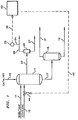
- FIG. 1 is a diagrammatic illustration of an embodiment of a polymerization reaction and recovery system which utilizes the present invention.
- FIG. 2 is a diagrammatic illustration of an alternative embodiment of a polymerization reaction and recovery system which utilizes the present invention.
- the invention is described in terms of the polymerization of ethylene. However, the invention is applicable to any polymerization process where it is desired to control the unreacted monomer concentration.
- Lines designated as signal lines in the drawings are electrical or pneumatic in these embodiments.
- the signals provided from any transducer are electrical in form.
- the signals provided from flow sensors will generally be pneumatic in form. Transducing of these signals is not illustrated for the sake of simplicity because it is well known in the art that if flow is measured in pneumatic form it must be transduced to electrical form if it is to be transmitted in electrical form by a flow transducer. Also, the transducing of the signals from analog form to digital form or from digital form to analog form is not illustrated because such transducing is well known in the art.
- the invention is applicable to mechanical, hydraulic or other signal means for transmitting information. In almost all control systems some combination of electrical, pneumatic, mechanical or hydraulic signals will be used. However, use of any other type of signal transmission, compatible with the process and equipment in use, is within scope of the invention.
- a polymerization reactor 11 Ethylene, and optionally a comonomer, such as hexene-1, is provided to polymerization reactor 11 through conduit means 12.
- a diluent such as isobutane is provided to the polymerization reactor 11 through conduit means 14 and a catalyst, such as chromium oxide on silica catalyst or silica-titania catalyst, is provided to the polymerization reactor 11 through conduit means 15.
- reaction effluent is removed from the reactor 11 through conduit means 17 and is provided to the flash tank 18.
- the reaction effluent will be comprised of polyethylene, unreacted ethylene, and isobutane. Catalyst will generally be contained in the polyethylene.
- the polyethylene is separated from the unreacted ethylene and the isobutane in the flash tank 18.
- Polyethylene is removed from high pressure tank 18 through conduit means 19.
- Unreacted ethylene and isobutane are removed from the flash tank 18 through conduit means 21.
- the pressure in flash tank 18 will vary depending on the nature of the diluent and monomer and the temperature selected. Typically, pressures above about 100 psig can be employed. Preferably, pressures in the range from about 100 to about 300 psig will be utilized; more preferably, from 200 to 250 psig. In contrast, polymerization systems utilizing only a low pressure flash tank will typically utilize pressures in the range of 0 psig to 75 psig.
- Polyethylene removed from the flash tank 18 through conduit means 19 will be treated to remove any remaining monomer and diluent.
- Such treatments can include a second flash in a low pressure flash tank and/or drying in a conventional dryer.
- Diluent and monomer are removed as vapor from flash tank 18 via conduit 21 and subsequently condensed without compression by heat exchange with a heat exchange fluid in a heat exchanger (not shown). The diluent and monomer can then be returned to reactor 11.
- an effective analyzing amount of reaction effluent is removed via conduit 23 from reactor 11.
- an effective analyzing amount of reactor effluent can be taken from conduit 17; however, direct removal from the reactor is preferable.
- an effective analyzing amount will be a minor volume proportion of the amount of effluent produced by the polymerization reactor.
- a polymerization system that produces effluent containing on the order of 35,000 lbs/hr of polymer, and 30,000 lbs/hr diluent and monomer would typically have a sample size of from about 20 lbs/hr to about 100 lbs/hr, with about 35% of the sample being polymer.
- such a sample would be from about 20 lbs/hr to about 40 lbs/hr.
- Low pressure flash tank 25 will typically operate with the pressure below about 75 psig; preferably at a pressure in the range of about 0 psig to about 30 psig, and most preferably from 0 psig to 10 psig.
- flash tank 25 vaporization of the monomer and diluent occurs; however, vaporization can also occur at least partially within conduit 23.
- flash tank 25 a more complete separation between the polyethylene and the unreacted ethylene and isobutane occurs than is achieved in high pressure flash tank 18.
- Low pressure flash tank 25 need not have the volume capacity of the high pressure flash tank because it will only be flashing an effective analyzing amount of reaction effluent. Typically, low pressure flash tank 25 will have a volume capacity of from about 2 to about 5 cubic feet.
- Polyethylene is removed from flash tank 25 through conduit means 27. Unreacted ethylene and isobutane are removed from flash tank 25 through conduit means 29. A sample of the fluid flowing through conduit means 29 is provided to analyzer transducer 33 through conduit means 34. The remaining fluid flowing through conduit 29 can be compressed and recycled back to the polymerization reactor if desired.
- the analyzer transducer 33 is preferably a chromatographic analyzer.
- the analyzer transducer 33 provides an output signal 36 which is representative of the concentration of ethylene in the fluid flowing through conduit 29. Essentially, signal 36 is representative of the concentration of unreacted ethylene removed from reactor 11.
- Signal 36 is provided from the analyzer transducer 33 as an input to computer 40.
- computer 40 determines the concentration of unreacted ethylene in reactor 11 and determines whether adjustment of the in flowing ethylene monomer is needed. If adjustment is needed, then computer 40 sends a signal 42 to valve 44. Valve 44 controls the flow of ethylene through conduit 12 and into reactor 11.
- the system instead of adjusting monomer feed through conduit 12 the system also could be set up so that diluent feed through conduit 14 or catalyst feed through conduit 16 are adjusted in response to a signal from computer 40.
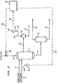
- FIG. 2 an embodiment where catalyst feed is adjusted in response to a signal from computer 40 is shown.
- the embodiment of FIG. 2 operates similarly to that of FIG. 1, except that conduit means 12 has sensor 50 which is in communication with transducer 52, and conduit 15 has a valve 58 which regulates catalyst flow through conduit 15.
- Flow transducer 52 in combination with flow sensor 50, which is operably located in conduit means 12, provides an output signal 54 which is representative of the flow rate of ethylene through conduit means 12.
- Signal 54 is provided from the flow transducer 52 as an input to computer 40.
- the computer In response to signal 54, from transducer 52, and signal 36, from analyzer transducer 33, the computer provides output signal 56, which is representative of the desired catalyst feed rate. In response to signal 56, valve 58 is adjusted to feed the appropriate amount of catalyst to reactor 11.
- valve 58 located in conduit means 15, will be a ball check feeder or shot feeder.
- the valve fills with a mixture of catalyst and diluent.
- the catalyst feeder valve 15 is actuated so this mixture is dumped into reactor 11.
- the catalyst feeder valve 15 is then recycled to a closed position and is refueled in preparation for the next actuation.
- valve 58 When valve 58 is a feeder valve, valve 58 will dump catalyst in response to signal 56.
- the computer determines the correct period between catalyst dumps necessary to maintain the desired amount of monomer within the reactor and sends signal 56 at the end of the period.
- conduit 23 In operation, care must be taken to prevent plugging of conduit 23 by the buildup of polymer. To prevent such plugging, conduit 23 should not be pocketed and preferably, it should be sloped at an angle toward flash tank 25 so that conduit 23 has no horizontal runs. Preferably, conduit 23 would be sloped downward at an angle between about 45° toward flash tank 25.
Abstract
Description
- This invention relates to process control. In one aspect this invention relates to a method and apparatus for maintaining a desired unreacted monomer concentration in a polymerization reactor.
- In a typical polymerization reaction, monomer, diluent and catalyst are fed to a reactor where the monomer is polymerized. The diluent does not react but is typically utilized to control solids concentration and also to provide a convenient mechanism for introducing the catalyst into the reactor. The reactor effluent, a mixture of polymer, diluent and unreacted monomer, is removed from the reactor and fed to a flash tank where the polymer is separated from the diluent and unreacted monomer. Typically, catalyst will be contained in the polymer.
- It is important to control the concentration of the unreacted monomer within the reactor because some of the properties of the polymer produced, such as melt index are highly dependent on the unreacted monomer concentration. Typically, the unreacted monomer concentration has been controlled by manipulating the monomer feed rate, the diluent feed rate, or the catalyst feed rate.
- Additionally, for economical operation it is desirable that the unreacted monomer in the reactor effluent be recovered and recycled to the polymerization reactor. Processes for the recovery and recycling of the diluent have been disclosed in U.S. Patents 3,639,374 and 4,424,341. Such processes are generally one-stage flash processes with a low pressure recovery of the monomer and diluent after the flashing, a one-stage flash process with a high pressure recovery of the diluent and the monomer within the reactor after the flashing, or a two-stage flash process with the recovery of a major portion of the monomer and diluent after the high pressure flash while the diluent and monomer are still at a sufficient pressure to avoid needing recompression.
- In a one-stage flash process with a low pressure recovery, a slurry of polymer and diluent is collected in one or more settling legs of the polymerization reactor. Next the slurry is discharged to a flash vessel wherein the mixture is flashed to a low pressure such as about 20 psia. While the flashing results in substantially complete removal of the diluent and monomer from the polymer, it is necessary to recompress the vaporized diluent and monomer in order to be able to condense them to liquid suitable for recycling to the polymerization reactor. The cost of recompression and the utilities for its operation often amounts to a significant portion of the expense involved in producing the polymer.
- When a high pressure flash is utilized, recovery of the diluent and monomer after the high pressure flash reduces the need for recompression of the vaporized diluent and monomer before recycling to the polymerization reactor. Thus, the use of a high pressure flash results in a reduction of the expense involved in producing the polymer. In a one-stage flash with low pressure recovery, direct sampling of the monomer and diluent gas gives accurate analysis of the amount of monomer in the polymerization reactor. However, when a high pressure flash recovery is utilized, a significant portion of the monomer is retained with the polymer solids so that a direct sampling of the gases from the high pressure flash tank will result in an inaccurate analysis of the amount of monomer in the polymerization reactor. Thus, it would be desirable to develop an accurate system of determining the amount of monomer in the polymerization reactor for a polymerization system using a high pressure flash, in order to control the concentration of the unreacted monomer in the polymerization reactor and, also, realize the cost benefits associated with utilizing a high pressure flash.
- It is therefore an object of the present invention to provide a method and apparatus capable of accurate analysis of the amount of monomer in the polymerization reactor when a high pressure flash tank is utilized for monomer recovery.
- In accordance with the present invention a method and apparatus for polymerizing a monomer in a polymerization reactor is provided wherein a polymerization effluent containing polymer and unreacted monomer is withdrawn from the polymerization reactor with a major part of the effluent being sent to a flash vessel for separation of the polymer from the monomer at a pressure above about 100 psig and an effective analyzing amount of the polymerization effluent being sent to a low pressure flash vessel for flash separation at a pressure below about 75 psig to produce a low pressure polymer portion and a low pressure monomer portion. The low pressure monomer portion is analyzed to produce a signal representative of at least one condition in the polymerization reactor and the conditions in the reactor are manipulated in response to the signal.
- FIG. 1 is a diagrammatic illustration of an embodiment of a polymerization reaction and recovery system which utilizes the present invention.
- FIG. 2 is a diagrammatic illustration of an alternative embodiment of a polymerization reaction and recovery system which utilizes the present invention.
- The invention is described in terms of the polymerization of ethylene. However, the invention is applicable to any polymerization process where it is desired to control the unreacted monomer concentration.
- Lines designated as signal lines in the drawings are electrical or pneumatic in these embodiments. Generally, the signals provided from any transducer are electrical in form. However, the signals provided from flow sensors will generally be pneumatic in form. Transducing of these signals is not illustrated for the sake of simplicity because it is well known in the art that if flow is measured in pneumatic form it must be transduced to electrical form if it is to be transmitted in electrical form by a flow transducer. Also, the transducing of the signals from analog form to digital form or from digital form to analog form is not illustrated because such transducing is well known in the art.
- The invention is applicable to mechanical, hydraulic or other signal means for transmitting information. In almost all control systems some combination of electrical, pneumatic, mechanical or hydraulic signals will be used. However, use of any other type of signal transmission, compatible with the process and equipment in use, is within scope of the invention.
- Referring now to FIG. 1, there is illustrated a
polymerization reactor 11. Ethylene, and optionally a comonomer, such as hexene-1, is provided topolymerization reactor 11 through conduit means 12. In like manner, a diluent such as isobutane is provided to thepolymerization reactor 11 through conduit means 14 and a catalyst, such as chromium oxide on silica catalyst or silica-titania catalyst, is provided to thepolymerization reactor 11 through conduit means 15. - The majority of the reaction effluent is removed from the
reactor 11 through conduit means 17 and is provided to theflash tank 18. The reaction effluent will be comprised of polyethylene, unreacted ethylene, and isobutane. Catalyst will generally be contained in the polyethylene. - The polyethylene is separated from the unreacted ethylene and the isobutane in the
flash tank 18. Polyethylene is removed fromhigh pressure tank 18 through conduit means 19. Unreacted ethylene and isobutane are removed from theflash tank 18 through conduit means 21. - Within
flash tank 18 the reaction effluent is exposed to a pressure drop. The pressure drop is such that a major portion of diluent and monomer will be vaporized. Vaporization can occur at least partially withinconduit 17. The pressure inflash tank 18 will vary depending on the nature of the diluent and monomer and the temperature selected. Typically, pressures above about 100 psig can be employed. Preferably, pressures in the range from about 100 to about 300 psig will be utilized; more preferably, from 200 to 250 psig. In contrast, polymerization systems utilizing only a low pressure flash tank will typically utilize pressures in the range of 0 psig to 75 psig. - Polyethylene removed from the
flash tank 18 through conduit means 19 will be treated to remove any remaining monomer and diluent. Such treatments can include a second flash in a low pressure flash tank and/or drying in a conventional dryer. - Diluent and monomer are removed as vapor from
flash tank 18 viaconduit 21 and subsequently condensed without compression by heat exchange with a heat exchange fluid in a heat exchanger (not shown). The diluent and monomer can then be returned toreactor 11. - An effective analyzing amount of reaction effluent is removed via
conduit 23 fromreactor 11. Optionally, an effective analyzing amount of reactor effluent can be taken fromconduit 17; however, direct removal from the reactor is preferable. Typically, an effective analyzing amount will be a minor volume proportion of the amount of effluent produced by the polymerization reactor. For example, a polymerization system that produces effluent containing on the order of 35,000 lbs/hr of polymer, and 30,000 lbs/hr diluent and monomer would typically have a sample size of from about 20 lbs/hr to about 100 lbs/hr, with about 35% of the sample being polymer. Preferably, such a sample would be from about 20 lbs/hr to about 40 lbs/hr. - The reaction effluent removed through conduit means 23 is provided to low
pressure flash tank 25. Lowpressure flash tank 25 will typically operate with the pressure below about 75 psig; preferably at a pressure in the range of about 0 psig to about 30 psig, and most preferably from 0 psig to 10 psig. Inflash tank 25 vaporization of the monomer and diluent occurs; however, vaporization can also occur at least partially withinconduit 23. In flash tank 25 a more complete separation between the polyethylene and the unreacted ethylene and isobutane occurs than is achieved in highpressure flash tank 18. - Low
pressure flash tank 25 need not have the volume capacity of the high pressure flash tank because it will only be flashing an effective analyzing amount of reaction effluent. Typically, lowpressure flash tank 25 will have a volume capacity of from about 2 to about 5 cubic feet. - Polyethylene is removed from
flash tank 25 through conduit means 27. Unreacted ethylene and isobutane are removed fromflash tank 25 through conduit means 29. A sample of the fluid flowing through conduit means 29 is provided toanalyzer transducer 33 through conduit means 34. The remaining fluid flowing throughconduit 29 can be compressed and recycled back to the polymerization reactor if desired. - The
analyzer transducer 33 is preferably a chromatographic analyzer. Theanalyzer transducer 33 provides anoutput signal 36 which is representative of the concentration of ethylene in the fluid flowing throughconduit 29. Essentially, signal 36 is representative of the concentration of unreacted ethylene removed fromreactor 11.Signal 36 is provided from theanalyzer transducer 33 as an input tocomputer 40. In response to signal 36,computer 40 determines the concentration of unreacted ethylene inreactor 11 and determines whether adjustment of the in flowing ethylene monomer is needed. If adjustment is needed, thencomputer 40 sends asignal 42 to valve 44. Valve 44 controls the flow of ethylene throughconduit 12 and intoreactor 11. - Different control systems for
computer 40 are known in the art such as those disclosed in U.S. Patent 4,543,637 and 4,628,034; the disclosures of which are hereby incorporated by reference. - Additionally, instead of adjusting monomer feed through
conduit 12 the system also could be set up so that diluent feed throughconduit 14 or catalyst feed through conduit 16 are adjusted in response to a signal fromcomputer 40. - Referring now to FIG 2, an embodiment where catalyst feed is adjusted in response to a signal from
computer 40 is shown. The embodiment of FIG. 2 operates similarly to that of FIG. 1, except that conduit means 12 hassensor 50 which is in communication withtransducer 52, andconduit 15 has avalve 58 which regulates catalyst flow throughconduit 15. -
Flow transducer 52, in combination withflow sensor 50, which is operably located in conduit means 12, provides anoutput signal 54 which is representative of the flow rate of ethylene through conduit means 12.Signal 54 is provided from theflow transducer 52 as an input tocomputer 40. - In response to signal 54, from
transducer 52, and signal 36, fromanalyzer transducer 33, the computer providesoutput signal 56, which is representative of the desired catalyst feed rate. In response to signal 56,valve 58 is adjusted to feed the appropriate amount of catalyst toreactor 11. - Typically,
valve 58, located in conduit means 15, will be a ball check feeder or shot feeder. The valve fills with a mixture of catalyst and diluent. Periodically, thecatalyst feeder valve 15 is actuated so this mixture is dumped intoreactor 11. Thecatalyst feeder valve 15 is then recycled to a closed position and is refueled in preparation for the next actuation. - When
valve 58 is a feeder valve,valve 58 will dump catalyst in response to signal 56. Thus, the computer determines the correct period between catalyst dumps necessary to maintain the desired amount of monomer within the reactor and sendssignal 56 at the end of the period. - In operation, care must be taken to prevent plugging of
conduit 23 by the buildup of polymer. To prevent such plugging,conduit 23 should not be pocketed and preferably, it should be sloped at an angle towardflash tank 25 so thatconduit 23 has no horizontal runs. Preferably,conduit 23 would be sloped downward at an angle between about 45° towardflash tank 25. - While the invention has been described in terms of the presently preferred embodiment, reasonable variations and modifications are possible by those skilled in the art and such variations are within the scope of the described invention and the appended claims.
Claims (11)
- In a polymerization process wherein monomer and catalyst are provided to a polymerization reactor, and a polymerization effluent, containing polymer and unreacted monomer, is withdrawn from said polymerization reactor and flash separated at a pressure above about 0.69 MPa gauge to separate said polymer from said monomer to produce a polymer portion and a monomer portion, characterized by(a) withdrawing an analyzable amount of said polymerization effluent before said flash separation;(b) flash separating said analyzable amount of said polymerization effluent at a pressure below about 0.52 MPa gauge to produce a polymer sample and a monomer sample;(c) analyzing said monomer sample to produce a signal representative of at least one condition in the polymerization reactor; and(d) manipulating at least one condition in the polymerization reactor in response to said signal.
- The method of claim 1 wherein said monomer portion is recycled back to said polymerization reactor without recompression.
- The method of claim 1 wherein said monomer sample is recompressed and returned to said polymerization reactor.
- The method of any of the preceding claims wherein said signal is representative of the concentration of monomer in said polymerization reactor.
- The method of any of the preceding claims wherein in step (d) the rate that catalyst is provided to said polymerization reactor and/or the rate that monomer is provided to said polymerization reactor is manipulated in response to said signal.
- The method of any of the preceding claims wherein said flash separation in step (b) occurs at a pressure in the range of from 0 to 0.07 MPa gauge.
- An apparatus comprising- a polymerization reactor;- means for providing monomer to said polymerization reactor;- means for providing catalyst to said polymerization reactor;- means for removing the reaction effluent containing polymer and unreacted monomer from said polymerization reactor;- first flash separation means for receiving a major portion of said reaction effluent and flash separating said urreacted monomer from said polymer at a pressure above about 0.69 MPa gauge;- second flash separation means for receiving a minor portion of said reaction effluent and flash separating said urreacted monomer from said polymer at a pressure below about 0.52 MPa gauge;- means for analyzing said monomer separated from said minor portion of said reaction effluent to produce a signal representative of at least one condition in the polymerization reactor; and- means for manipulating at least one condition in said polymerization reactor in response to said signal.
- The apparatus of claim 7 wherein said flash separation in said second flash separation means occurs at a pressure in the range of 0 to 0.07 MPa gauge.
- The apparatus of claim 7 wherein said means for analyzing said monomer comprises an analyzer transducer and a computer.
- The apparatus of claim 7 wherein said signal is representative of the concentration of monomer in said polymerization reactor.
- The apparatus of claim 7 wherein said means for manipulating changes the rate that monomer is provided to said polymerization reactor and/or the rate that catalyst is provided to said polymerization reactor.
Priority Applications (6)
| Application Number | Priority Date | Filing Date | Title |
|---|---|---|---|
| US08/014,934 US5387659A (en) | 1993-02-08 | 1993-02-08 | Flash gas sampling for polymerization reactions |
| EP94118003A EP0712865B1 (en) | 1993-02-08 | 1994-11-15 | Flash gas sampling for polymerization reactions |
| DE69410799T DE69410799T2 (en) | 1993-02-08 | 1994-11-15 | Flash gas sampling for polymerization reactions |
| ES94118003T ES2116510T3 (en) | 1993-02-08 | 1994-11-15 | SAMPLING OF INSTANT VAPORIZATION GAS FOR POLYMERIZATION REACTIONS. |
| CA002136876A CA2136876C (en) | 1993-02-08 | 1994-11-29 | Flash gas sampling for polymerization reactions |
| CN94119186A CN1053674C (en) | 1993-02-08 | 1994-12-22 | Flash gas sampling for polymerization reactions |
Applications Claiming Priority (3)
| Application Number | Priority Date | Filing Date | Title |
|---|---|---|---|
| US08/014,934 US5387659A (en) | 1993-02-08 | 1993-02-08 | Flash gas sampling for polymerization reactions |
| EP94118003A EP0712865B1 (en) | 1993-02-08 | 1994-11-15 | Flash gas sampling for polymerization reactions |
| CN94119186A CN1053674C (en) | 1993-02-08 | 1994-12-22 | Flash gas sampling for polymerization reactions |
Publications (2)
| Publication Number | Publication Date |
|---|---|
| EP0712865A1 true EP0712865A1 (en) | 1996-05-22 |
| EP0712865B1 EP0712865B1 (en) | 1998-06-03 |
Family
ID=37101933
Family Applications (1)
| Application Number | Title | Priority Date | Filing Date |
|---|---|---|---|
| EP94118003A Expired - Lifetime EP0712865B1 (en) | 1993-02-08 | 1994-11-15 | Flash gas sampling for polymerization reactions |
Country Status (6)
| Country | Link |
|---|---|
| US (1) | US5387659A (en) |
| EP (1) | EP0712865B1 (en) |
| CN (1) | CN1053674C (en) |
| CA (1) | CA2136876C (en) |
| DE (1) | DE69410799T2 (en) |
| ES (1) | ES2116510T3 (en) |
Cited By (1)
| Publication number | Priority date | Publication date | Assignee | Title |
|---|---|---|---|---|
| WO1998053909A1 (en) * | 1997-05-29 | 1998-12-03 | E.I. Du Pont De Nemours And Company | Process control method for vented polymerizers |
Families Citing this family (23)
| Publication number | Priority date | Publication date | Assignee | Title |
|---|---|---|---|---|
| US6239235B1 (en) * | 1997-07-15 | 2001-05-29 | Phillips Petroleum Company | High solids slurry polymerization |
| US6815511B2 (en) * | 1997-07-15 | 2004-11-09 | Chevron Phillips Chemical Company, Lp | Continuous withdrawal from high solids slurry polymerization |
| CN101260167B (en) * | 1997-12-23 | 2012-11-14 | 陶氏环球技术有限责任公司 | Finishing design to increase the polymer content in an olefin solution polymerization process |
| US7268194B2 (en) * | 1998-03-20 | 2007-09-11 | Exxonmobil Chemical Patents Inc. | Continuous slurry polymerization process and apparatus |
| KR100531628B1 (en) | 1998-03-20 | 2005-11-29 | 엑손모빌 케미칼 패턴츠 인코포레이티드 | Continuous slurry polymerization volatile removal |
| US6281300B1 (en) * | 1998-03-20 | 2001-08-28 | Exxon Chemical Patents, Inc. | Continuous slurry polymerization volatile removal |
| US20020111441A1 (en) | 1998-03-20 | 2002-08-15 | Kendrick James Austin | Continuous slurry polymerization volatile removal |
| US6967230B2 (en) * | 1998-12-18 | 2005-11-22 | Chevron Phillips Chemical Company Lp | Process for producing polyolefins |
| US7005485B2 (en) * | 1998-12-18 | 2006-02-28 | Chevron Phillips Chemical Company Lp | Process for producing polyolefins |
| CN1361794A (en) * | 1999-07-15 | 2002-07-31 | 菲利浦石油公司 | Slotted slurry take off |
| US6936665B2 (en) * | 2001-09-26 | 2005-08-30 | Bp Corporation North America Inc. | Integrated advanced chemical process control |
| WO2004024781A1 (en) * | 2002-09-13 | 2004-03-25 | Chevron Phillips Chemical Company Lp | Process and apparatus for reducing take-off valve plugging in a polymerization process |
| WO2004027264A2 (en) * | 2002-09-17 | 2004-04-01 | Chevron Phillips Chemical Company Lp | Improved pumping apparatus and process for slurry polymerization in loop reactors |
| CN1708352A (en) * | 2002-10-28 | 2005-12-14 | Bp北美公司 | Process and method for chemical manufacturing using transformation of on-line instrumentation data |
| US20050095176A1 (en) * | 2003-10-31 | 2005-05-05 | Hottovy John D. | Method and apparatus for reducing reactor fines |
| CA2579754C (en) | 2004-08-27 | 2011-07-05 | Chevron Phillips Chemical Company Lp | Energy efficient polyolefin process |
| US7629421B2 (en) * | 2005-12-21 | 2009-12-08 | Chevron Phillips Chemical Company Lp | Monomer recovery by returning column overhead liquid to the reactor |
| US8344078B2 (en) | 2010-05-21 | 2013-01-01 | Chevron Phillips Chemical Company Lp | Continuous take off technique and pressure control of polymerization reactors |
| US8703063B2 (en) | 2010-06-21 | 2014-04-22 | Chevron Phillips Chemical Company Lp | System and method for closed relief of a polyolefin loop reactor system |
| US9163564B2 (en) | 2010-06-21 | 2015-10-20 | Chevron Phillips Chemical Company Lp | Method and system for energy generation in a chemical plant by utilizing flare gas |
| US8597582B2 (en) | 2011-06-30 | 2013-12-03 | Chevron Phillips Chemical Company Lp | Flashline heater system and method |
| US10029230B1 (en) | 2017-01-24 | 2018-07-24 | Chevron Phillips Chemical Company Lp | Flow in a slurry loop reactor |
| CN106885713B (en) * | 2017-03-20 | 2019-06-11 | 上海锐宇流体系统有限公司 | High pressure easily flashes mixing liquid sampler |
Citations (3)
| Publication number | Priority date | Publication date | Assignee | Title |
|---|---|---|---|---|
| EP0124333A2 (en) * | 1983-04-25 | 1984-11-07 | The Babcock & Wilcox Company | Apparatus for controlling polymerisation reactors |
| US4543637A (en) * | 1982-07-16 | 1985-09-24 | Phillips Petroleum Company | Generation of a set point for process control |
| US4619901A (en) * | 1985-02-21 | 1986-10-28 | Phillips Petroleum Company | Control of polymerization reaction |
Family Cites Families (4)
| Publication number | Priority date | Publication date | Assignee | Title |
|---|---|---|---|---|
| US3321280A (en) * | 1964-06-26 | 1967-05-23 | Exxon Research Engineering Co | Computer control method for production of butyl rubber |
| US3847554A (en) * | 1973-02-05 | 1974-11-12 | Phillips Fibers Corp | Analysis of materials to measure vaporizable components |
| US3998995A (en) * | 1974-12-02 | 1976-12-21 | Phillips Petroleum Company | Polymerization method and apparatus |
| US4628034A (en) * | 1982-07-01 | 1986-12-09 | Phillips Petroleum Company | Control of a polymerization reaction |
-
1993
- 1993-02-08 US US08/014,934 patent/US5387659A/en not_active Expired - Fee Related
-
1994
- 1994-11-15 ES ES94118003T patent/ES2116510T3/en not_active Expired - Lifetime
- 1994-11-15 DE DE69410799T patent/DE69410799T2/en not_active Expired - Fee Related
- 1994-11-15 EP EP94118003A patent/EP0712865B1/en not_active Expired - Lifetime
- 1994-11-29 CA CA002136876A patent/CA2136876C/en not_active Expired - Fee Related
- 1994-12-22 CN CN94119186A patent/CN1053674C/en not_active Expired - Fee Related
Patent Citations (3)
| Publication number | Priority date | Publication date | Assignee | Title |
|---|---|---|---|---|
| US4543637A (en) * | 1982-07-16 | 1985-09-24 | Phillips Petroleum Company | Generation of a set point for process control |
| EP0124333A2 (en) * | 1983-04-25 | 1984-11-07 | The Babcock & Wilcox Company | Apparatus for controlling polymerisation reactors |
| US4619901A (en) * | 1985-02-21 | 1986-10-28 | Phillips Petroleum Company | Control of polymerization reaction |
Cited By (1)
| Publication number | Priority date | Publication date | Assignee | Title |
|---|---|---|---|---|
| WO1998053909A1 (en) * | 1997-05-29 | 1998-12-03 | E.I. Du Pont De Nemours And Company | Process control method for vented polymerizers |
Also Published As
| Publication number | Publication date |
|---|---|
| EP0712865B1 (en) | 1998-06-03 |
| US5387659A (en) | 1995-02-07 |
| ES2116510T3 (en) | 1998-07-16 |
| CN1053674C (en) | 2000-06-21 |
| CA2136876A1 (en) | 1995-08-09 |
| DE69410799D1 (en) | 1998-07-09 |
| CN1125322A (en) | 1996-06-26 |
| CA2136876C (en) | 1998-04-28 |
| DE69410799T2 (en) | 1998-10-01 |
Similar Documents
| Publication | Publication Date | Title |
|---|---|---|
| US5387659A (en) | Flash gas sampling for polymerization reactions | |
| US6042790A (en) | Apparatus for maintaining unreacted monomer concentration in a polymerization reactor | |
| EP1713832B1 (en) | Device and method for improving a polymerization reaction by taking out and analysing a sample | |
| EP1415999B1 (en) | Process and apparatus for producing olefin polymers | |
| US7740808B2 (en) | Process and apparatus for producing olefin polymers | |
| EP1064086B1 (en) | Continuous slurry polymerization volatile removal | |
| US6037184A (en) | Method and apparatus for taking sample | |
| EP1080116A2 (en) | Continuous volatile removal in slurry polymerization | |
| US4619901A (en) | Control of polymerization reaction | |
| US6592827B1 (en) | Sampling system for fluidized bed gas phase polymerization reaction systems | |
| EP0460594A2 (en) | Method and apparatus for taking samples | |
| RU2141485C1 (en) | Method of polymerization and device for its realization | |
| KR100251075B1 (en) | A method and an apparatus for polymerization and recovery of polymer | |
| JP2990028B2 (en) | Method and apparatus for maintaining monomer concentration | |
| JP2001181307A (en) | Sampling system for fluidized bed gas phase polymerization reaction | |
| US4515008A (en) | Polymerization rate detection method | |
| US4628034A (en) | Control of a polymerization reaction | |
| US4347098A (en) | Solvent vapor recovery from a polymer solution | |
| EP1344563B1 (en) | Continuous slurry polymerisation volatile removal | |
| EP2404942A1 (en) | Interlock and process | |
| US4533517A (en) | Control of a polymerization reaction | |
| HU217853B (en) | Procedure and apparatus for process control of the monomer concentration of polymeryzing autoclav | |
| AU2002300690B2 (en) | Continuous slurry polymerization volatile removal | |
| KR20070018960A (en) | Process and apparatus for producing olefin polymers |
Legal Events
| Date | Code | Title | Description |
|---|---|---|---|
| PUAI | Public reference made under article 153(3) epc to a published international application that has entered the european phase |
Free format text: ORIGINAL CODE: 0009012 |
|
| AK | Designated contracting states |
Kind code of ref document: A1 Designated state(s): BE DE ES FR GB IT NL SE |
|
| 17P | Request for examination filed |
Effective date: 19960920 |
|
| 17Q | First examination report despatched |
Effective date: 19961223 |
|
| GRAG | Despatch of communication of intention to grant |
Free format text: ORIGINAL CODE: EPIDOS AGRA |
|
| GRAG | Despatch of communication of intention to grant |
Free format text: ORIGINAL CODE: EPIDOS AGRA |
|
| GRAG | Despatch of communication of intention to grant |
Free format text: ORIGINAL CODE: EPIDOS AGRA |
|
| GRAH | Despatch of communication of intention to grant a patent |
Free format text: ORIGINAL CODE: EPIDOS IGRA |
|
| GRAH | Despatch of communication of intention to grant a patent |
Free format text: ORIGINAL CODE: EPIDOS IGRA |
|
| GRAA | (expected) grant |
Free format text: ORIGINAL CODE: 0009210 |
|
| AK | Designated contracting states |
Kind code of ref document: B1 Designated state(s): BE DE ES FR GB IT NL SE |
|
| ITF | It: translation for a ep patent filed |
Owner name: JACOBACCI & PERANI S.P.A. |
|
| REF | Corresponds to: |
Ref document number: 69410799 Country of ref document: DE Date of ref document: 19980709 |
|
| REG | Reference to a national code |
Ref country code: ES Ref legal event code: FG2A Ref document number: 2116510 Country of ref document: ES Kind code of ref document: T3 |
|
| ET | Fr: translation filed | ||
| PLBE | No opposition filed within time limit |
Free format text: ORIGINAL CODE: 0009261 |
|
| STAA | Information on the status of an ep patent application or granted ep patent |
Free format text: STATUS: NO OPPOSITION FILED WITHIN TIME LIMIT |
|
| 26N | No opposition filed | ||
| REG | Reference to a national code |
Ref country code: GB Ref legal event code: IF02 |
|
| PGFP | Annual fee paid to national office [announced via postgrant information from national office to epo] |
Ref country code: GB Payment date: 20021002 Year of fee payment: 9 |
|
| PGFP | Annual fee paid to national office [announced via postgrant information from national office to epo] |
Ref country code: NL Payment date: 20021011 Year of fee payment: 9 |
|
| PGFP | Annual fee paid to national office [announced via postgrant information from national office to epo] |
Ref country code: FR Payment date: 20021105 Year of fee payment: 9 |
|
| PGFP | Annual fee paid to national office [announced via postgrant information from national office to epo] |
Ref country code: SE Payment date: 20021106 Year of fee payment: 9 |
|
| PGFP | Annual fee paid to national office [announced via postgrant information from national office to epo] |
Ref country code: ES Payment date: 20021118 Year of fee payment: 9 |
|
| PGFP | Annual fee paid to national office [announced via postgrant information from national office to epo] |
Ref country code: DE Payment date: 20021127 Year of fee payment: 9 |
|
| PGFP | Annual fee paid to national office [announced via postgrant information from national office to epo] |
Ref country code: BE Payment date: 20021213 Year of fee payment: 9 |
|
| PG25 | Lapsed in a contracting state [announced via postgrant information from national office to epo] |
Ref country code: GB Free format text: LAPSE BECAUSE OF NON-PAYMENT OF DUE FEES Effective date: 20031115 |
|
| PG25 | Lapsed in a contracting state [announced via postgrant information from national office to epo] |
Ref country code: SE Free format text: LAPSE BECAUSE OF NON-PAYMENT OF DUE FEES Effective date: 20031116 |
|
| PG25 | Lapsed in a contracting state [announced via postgrant information from national office to epo] |
Ref country code: ES Free format text: LAPSE BECAUSE OF NON-PAYMENT OF DUE FEES Effective date: 20031117 |
|
| PG25 | Lapsed in a contracting state [announced via postgrant information from national office to epo] |
Ref country code: BE Free format text: LAPSE BECAUSE OF NON-PAYMENT OF DUE FEES Effective date: 20031130 |
|
| BERE | Be: lapsed |
Owner name: *PHILLIPS PETROLEUM CY Effective date: 20031130 |
|
| PG25 | Lapsed in a contracting state [announced via postgrant information from national office to epo] |
Ref country code: NL Free format text: LAPSE BECAUSE OF NON-PAYMENT OF DUE FEES Effective date: 20040601 |
|
| PG25 | Lapsed in a contracting state [announced via postgrant information from national office to epo] |
Ref country code: DE Free format text: LAPSE BECAUSE OF NON-PAYMENT OF DUE FEES Effective date: 20040602 |
|
| EUG | Se: european patent has lapsed | ||
| GBPC | Gb: european patent ceased through non-payment of renewal fee |
Effective date: 20031115 |
|
| PG25 | Lapsed in a contracting state [announced via postgrant information from national office to epo] |
Ref country code: FR Free format text: LAPSE BECAUSE OF NON-PAYMENT OF DUE FEES Effective date: 20040730 |
|
| NLV4 | Nl: lapsed or anulled due to non-payment of the annual fee |
Effective date: 20040601 |
|
| REG | Reference to a national code |
Ref country code: FR Ref legal event code: ST |
|
| REG | Reference to a national code |
Ref country code: ES Ref legal event code: FD2A Effective date: 20031117 |
|
| PG25 | Lapsed in a contracting state [announced via postgrant information from national office to epo] |
Ref country code: IT Free format text: LAPSE BECAUSE OF NON-PAYMENT OF DUE FEES;WARNING: LAPSES OF ITALIAN PATENTS WITH EFFECTIVE DATE BEFORE 2007 MAY HAVE OCCURRED AT ANY TIME BEFORE 2007. THE CORRECT EFFECTIVE DATE MAY BE DIFFERENT FROM THE ONE RECORDED. Effective date: 20051115 |