EP0712557B1 - Method and system for predicting ink consumption - Google Patents
Method and system for predicting ink consumption Download PDFInfo
- Publication number
- EP0712557B1 EP0712557B1 EP94923217A EP94923217A EP0712557B1 EP 0712557 B1 EP0712557 B1 EP 0712557B1 EP 94923217 A EP94923217 A EP 94923217A EP 94923217 A EP94923217 A EP 94923217A EP 0712557 B1 EP0712557 B1 EP 0712557B1
- Authority
- EP
- European Patent Office
- Prior art keywords
- cell
- ink
- cylinder
- recited
- engraving
- Prior art date
- Legal status (The legal status is an assumption and is not a legal conclusion. Google has not performed a legal analysis and makes no representation as to the accuracy of the status listed.)
- Expired - Lifetime
Links
- 238000000034 method Methods 0.000 title claims description 64
- 238000007639 printing Methods 0.000 claims description 41
- 239000002131 composite material Substances 0.000 claims description 10
- RYGMFSIKBFXOCR-UHFFFAOYSA-N Copper Chemical compound [Cu] RYGMFSIKBFXOCR-UHFFFAOYSA-N 0.000 claims description 3
- 229910052802 copper Inorganic materials 0.000 claims description 3
- 239000010949 copper Substances 0.000 claims description 3
- 239000000758 substrate Substances 0.000 claims description 2
- 230000003213 activating effect Effects 0.000 claims 1
- 210000004027 cell Anatomy 0.000 description 78
- 239000000463 material Substances 0.000 description 10
- 230000010354 integration Effects 0.000 description 9
- 238000007646 gravure printing Methods 0.000 description 6
- 241001422033 Thestylus Species 0.000 description 4
- 238000004364 calculation method Methods 0.000 description 4
- 210000002421 cell wall Anatomy 0.000 description 4
- 238000000862 absorption spectrum Methods 0.000 description 2
- 238000012886 linear function Methods 0.000 description 2
- 230000003287 optical effect Effects 0.000 description 2
- 238000010521 absorption reaction Methods 0.000 description 1
- 229910003460 diamond Inorganic materials 0.000 description 1
- 239000010432 diamond Substances 0.000 description 1
- 230000000694 effects Effects 0.000 description 1
- 238000001914 filtration Methods 0.000 description 1
- 238000005259 measurement Methods 0.000 description 1
- 230000000007 visual effect Effects 0.000 description 1
Images


Classifications
-
- B—PERFORMING OPERATIONS; TRANSPORTING
- B41—PRINTING; LINING MACHINES; TYPEWRITERS; STAMPS
- B41F—PRINTING MACHINES OR PRESSES
- B41F33/00—Indicating, counting, warning, control or safety devices
- B41F33/0027—Devices for scanning originals, printing formes or the like for determining or presetting the ink supply
-
- B—PERFORMING OPERATIONS; TRANSPORTING
- B41—PRINTING; LINING MACHINES; TYPEWRITERS; STAMPS
- B41F—PRINTING MACHINES OR PRESSES
- B41F31/00—Inking arrangements or devices
-
- B—PERFORMING OPERATIONS; TRANSPORTING
- B41—PRINTING; LINING MACHINES; TYPEWRITERS; STAMPS
- B41P—INDEXING SCHEME RELATING TO PRINTING, LINING MACHINES, TYPEWRITERS, AND TO STAMPS
- B41P2233/00—Arrangements for the operation of printing presses
- B41P2233/30—Measuring or controlling the consumption of ink
Definitions
- This invention relates to a method and a system for determining the volume of ink which is consumed by a printing form in a printing process, as mentioned in the preambles of claims 1 and 17.
- Such a process may use an electro-mechanically engraved gravure printing cylinder; for example, a gravure printing cylinder which has been engraved in accordance with the method disclosed in copending application, Serial No. 08/022,127, filed February 25, 1993 published as US 5,424,854.
- Such printing cylinders are engraved by an engraving head comprising a diamond stylus carried by a holder mounted on an arm projecting from a torsionally oscillated shaft.
- a sine wave driving signal is applied to a pair of opposed electromagnets to rotate the shaft trought an arc of approximately 0.25° at a frequency in the neighborhood of about 3,000 to 5,000 Hz.
- a video signal is added to the sine wave driving signal for urging the oscillating stylus into contact with the printing cylinder thereby engraving a series of controlled depth cells in the surface thereof.
- the printing cylinder rotates in synchronism with the oscillating movement of the stylus while a lead screw arrangement products axial movement of the engraving head so that the engraving head comes into engraving contact with the printing surface of the printing cylinder.
- the system has setup controls for quickly and easily setting up the engraving head to engrave cells of precisely controlled dimensions in the surface of a gravure printing cylinder.
- ink When such a printing cylinder is used in a gravure printing process, ink will be applied in an amount which is related to the total volume of all of the cells which have been so engraved. This is likewise true for gravure printing processes using printing cylinders which have been engraved by other engraving techniques.
- the US patent 4 944 593 there is disclosed a method and an apparatus for direct measuring the volume of surface depressions or cells of an engraved cylinder for a printing process.
- the method comprises the steps of filling the depressions be measured with a material which emits wave-length-shifted scattered light under irradiation, illuminating said material with a light source which has a wavelength that lies in the region of the absorption spectrum of said material, and measuring the intensity of the wavelength-shifted scattered light which is emitted by the material with a photo-detector.
- the measured intensities indicate the volumes of the surface depressions.
- the results of said measurements can be used to more exactly estimate the ink volume for a printing form in a printing process.
- Said apparatus for carrying out said method comprises a light source which is directed into said surface depressions, said depressions filled with material which emits light having a wavelength which lies in the absorption spectrum of said material, a first detector means mounted to receive and measure the intensities of the light emitted from said material when it is excited by the light source, a second detector means mounted to receive a part of the light from the light source, a first beam splitter which is mounted between said light source and said material for receiving and separating said part of said light, a second beam splitter for reflecting the light emitted by said irradiated material, said second beam splitter mounted in the light beam path between said first beam splitter and said material, a filter for filtering out light from the light source,said filter mounted between said second detector and said second beam splitter, and an amplifier and measuring means which are connect to said first and second detector means so as to measure the intesities of the light received by said first and second detector means.
- the apparatus further comprises a copy scanner having a light source and a light detector, optical means for concentrating light rays from said light source onto a copy supported by a rotating copy cylinder with the copy having a repeating pattern adapted to form a joint, said optical means directing light rays from the copy to said light detector, means associated with said copy scanner for sensing the copy density at different cirumferentially spaced locations on the rotating copy, means for comparing the density at the different locations, means for introducing a correction for differences in copy density, and means for controlling said drive means to cause the engraving at the joint to be corrected for unbalance in copy density at the different locations.
- An object of this invention is to provide a method and system for determining a volume of ink for an cylinder which is or is to be engraved.
- Another object of this invention is to provide a method and system for determining the amount of ink consumed by an engraved cylinder during printing.
- Still another object of this invention is to provide a method and system of determining the required ink volume in response to at least one input parameter, such as cell width, cell wall size, channel width, engraving width, taper requirements, circumferential linearization, balance correction, edge enhancement level, screen and screen angle.
- input parameter such as cell width, cell wall size, channel width, engraving width, taper requirements, circumferential linearization, balance correction, edge enhancement level, screen and screen angle.
- the method solving said objects is defined in claim 1.
- a method of predicting ink consumption in accordance with the present invention utilizes a series of steps as illustrated generally in Fig. 1.
- the object is to print N copies of an original image or of a composite image comprised of multiple images.
- the data defining an original or composite image may be generated and downloaded from a computer or it could be scanned, for example, from a graphic master or other medium capable of being scanned.
- the method of the invention begins by inputting the image data as indicated by block 24 of Fig. 1.
- the image data could be a group of files representing multiple images, each obtained from a different source.
- the images could be a single file of scanned or computer generated image data.
- a composite cylinder layout (block 25) is composed.
- This cylinder layout identifies the portion of each image which is to be engraved on the cylinder surface and specifies the exact geometric placement of that portion of each image.
- one or more of a plurality of engraving parameters may be input into the computer.
- the parameters of engraving width, taper requirements, circumferential linearization, balance correction, edge enhancement level, screen and screen angle, as well as others may be input into the computer.
- These parameters affect the size and placement of engraved cells on the cylinder.
- taper and circumferential linearization adjust engraved cells to eliminate visual discontinuities caused by spiral engraving.
- the edge enhancement level parameters provide a method to improve contrast at line or image edges.
- the screen and screen angle generally describe cell population and cell shape.
- the computer comprises means for considering each of the above parameters, as well as others, and for adjusting the densities of certain cells accordingly.
- cell shape parameters are input (block 26) which complete the definition of an engrave job.
- a histogram representing the image densities of each of the pixels may then be generated for the engrave job.
- Density values for a conventional electronic engraving machine are generally proportional to the voltages supplied to the engraving head.
- an electronic engraving machine is driven by a video signal and an AC signal.
- the video signal is generally adjusted so as to be proportional to a desired printing density.
- the density values used to compile the histogram are used for the engraving operation, as well as used to predict ink volume.
- the computer prepares a table of data representing a histogram of density values associated with the composite cylinder layout.
- the densities are digitized and set to one or another of a predetermined number of discrete values.
- a vector of length 1025 has been found to be convenient for this purpose. Each time the examination indicates a particular density value, the appropriate vector position is adjusted. This process continues until a histogram or table of densities is generated for the entire cylinder.
- the computer After the density table has been generated, the computer begins reading the tabulated density values (block 29) for calculation of associated cell volumes. Calculations are performed at blocks 31 and 32 to determine the volumes of each of the different cell sizes corresponding to the different density levels. Each computed cell volume is multiplied by the number of occurrences of that cell volume to obtain a cell volume subtotal (block 33). The subtotals are accumulated (for example, at block 34) in order to read the total volume of all engraved cells.
- the cell volume calculations use the setup parameters generated at block 26 to define the cell shape and geometry. These same parameters are used for controlling the engraving process (blocks 40-47) substantially as shown and described in Serial No. 08/022,127 which is assigned to the same assignee as the present invention and which is herein incorporated by reference and made a part hereof.
- a highlight voltage and cell width, a shadow voltage and cell width and a stylus angle are selected and input by the operator.
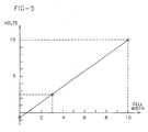
- the voltage and cell width corresponding to a shadow cell and a highlight cell may define a linear or non-linear function. In the embodiment being described, the voltage and cell width define a generally linear function, as shown in Fig. 5.
- the computer determines the width of that shadow cell.
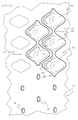
- Shadow cells 70 and highlight cells 76 may be engraved on the surface of a cylinder 10 as generally illustrated in Fig. 2.
- Shadow cells 70 may be connected by channels 72, the width of which may be adjusted by adjusting the video signal used for driving the engraving tool. If the shadow cells are not connected by a channel, the distance between cells in the direction of engraving is the vertical cell spacing 71, as shown in Fig. 2.
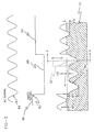
- an engraving tool 20 oscillates into cutting contact with cylinder 10 under control of a driving signal which is the sum of a video signal 82 and an AC signal 80.
- Video signal 82 may have a white level value 86 such that the tip of the engraving tool never gets closer to cylinder 10 than a predetermined white depth WD.
- the engraver engraves full depth shadow cells having a maximum depth BD.
- the tool then engraves a contour 84 having a minimum depth CD which is the channel depth.
- the engraver engraves highlight cells having a maximum depth HD.
- the preferred embodiment of this invention utilizes a minimum diagonal wall size 49 (Fig. 6) as a setup parameter.
- the minimum diagonal wall size 49 is the perpendicular distance between tangent lines to adjacent cell walls.
- the cell shape description mentioned above may be fine tuned if desired.
- the channel width associated with a cell shape description may be entered in which case the computer recalculates or adjusts the minimum diagonal wall size 49.
- a channel width of zero, indicating no channel may be entered into the computer.
- a vertical spacing between cells may be entered into the computer, and again, the computer will recalculate or adjust the minimum diagonal wall size. Therefore, it is significant to note that the computer comprises means for tuning the cell shape description to accommodate various inputs and parameters which may affect cell shape, geometry, and volume.
- All input parameters and fine tuning inputs may be shown on a monitor (not shown) which is operatively coupled to the computer.
- the volumes of the individual cell types are calculated by a process indicated by decision point 30 and blocks 31 and 32.
- the process involves calculating the cross-sectional area of the cell as a function of cell location (e.g. position along the cell) and then integrating the area along the length of the cell in the direction of the engraving track.
- the integration may be carried out in closed form (as defined by the equations below) or performed numerically. If the integration is carried out numerically, then a check is made immediately following each pass through the integration loop to determine whether integration of the cell has been completed.
- the volume for a cell is determined using one or the other of equations (1) and (2) below. It is to be noted that the cell volume will differ for a cell with a channel as opposed to a cell without a channel.
- ⁇ is the stylus tip angle
- s is screen in lines/micron.
- P is the period of the sine wave mentioned earlier herein.
- ⁇ is the screen angle
- D 0 depth of channel in microns.
- D 1 total depth the stylus travels into copper.
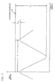
- Fig. 7 graphically illustrates the variables P, D 0 , and D 1 for a cell with a channel.
- L is the cell length in direction of cutting.
- D 1 is the depth of the cell.
- D 0 is the amplitude of the sine wave (to be derived from user inputs) minus the depth of the cell.
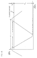
- Fig. 8 graphically illustrates the variables P, L, D 0 and D 1 for a cell without a channel.
- the process proceeds to select the next cell size and repeats the integration process. After completion of each volume computation, a check is made (Point 35) to determine whether the volumes of all cell sizes have been determined. If so, then the process proceeds to block 36 for a calculation of the volume of ink required for a single impression.
- the total computed cell volume is multiplied by a release factor R.
- the release factor accounts for factors, such as the absorption properties of the printing substrate, the viscosity of the ink, speed of the press and the like.
- This ink volume is multiplied by the number of impressions N (block 37) to obtain the required volume of ink for an entire press run. This completes the prediction of ink consumption and usage at block 38.
- the ink volume may then be used to provide an estimate of the amount of ink to fill an ink well of the printer (block 39).
- the integration is carried out numerically, then it is most convenient to perform the integration over a one-half wavelength distance and thereafter double the result.
- the numerical integration proceeds by moving from station-to-station along a profile of Fig. 3 and calculating the cross-sectional area at each station. This area is multiplied by the incremental distance between computing positions to obtain an incremental volume.
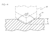
- FIG. 3 A typical stylus 20 for use in the practice of this invention is illustrated in phantom outline in Figs. 3 and 4.
- the tip of stylus 20 has two bevelled faces which produce a tip angle ⁇ , which may be about 120°.
- the stylus cuts a corresponding angular channel in the surface.
- Fig. 4 is a view taken perpendicular to the view of Fig. 3.
- the walls have a sinusoidal profile when viewed in a direction perpendicular to the engraving direction and conform to the shape of the engraving tip when viewed in a direction parallel to the direction of engraving.
- Each of the depressions illustrated in Fig. 3 represents an engraved printing cell.
- the volume of any printing cell may be computed by calculating the cross-sectional area as viewed in Fig. 4 and integrating that area over a one wavelength distance in the direction of engraving (e.g. parallel to engraving tracks 30).
- the wavelength distance is given by the period of the sine wave as defined above.
- this invention provides an ink management system and printing method for precisely determining the amount of ink required by a print cylinder, such as a gravure cylinder having a plurality of cells.
- the video data generated at block 28 may be applied to an engraving controller (not shown) for generation of an engraving signal at block 40.
- This engraving signal is used to position an engraving stylus, as described in detail below.
- the engraving stylus engraves a cell (block 44) and continues engraving cells until the last cell has been engraved (decision point 46).
Landscapes
- Manufacture Or Reproduction Of Printing Formes (AREA)
Description
- This invention relates to a method and a system for determining the volume of ink which is consumed by a printing form in a printing process, as mentioned in the preambles of claims 1 and 17.
- Such a process may use an electro-mechanically engraved gravure printing cylinder; for example, a gravure printing cylinder which has been engraved in accordance with the method disclosed in copending application, Serial No. 08/022,127, filed February 25, 1993 published as US 5,424,854. Such printing cylinders are engraved by an engraving head comprising a diamond stylus carried by a holder mounted on an arm projecting from a torsionally oscillated shaft. A sine wave driving signal is applied to a pair of opposed electromagnets to rotate the shaft trought an arc of approximately 0.25° at a frequency in the neighborhood of about 3,000 to 5,000 Hz.
- A video signal is added to the sine wave driving signal for urging the oscillating stylus into contact with the printing cylinder thereby engraving a series of controlled depth cells in the surface thereof. The printing cylinder rotates in synchronism with the oscillating movement of the stylus while a lead screw arrangement products axial movement of the engraving head so that the engraving head comes into engraving contact with the printing surface of the printing cylinder. The system has setup controls for quickly and easily setting up the engraving head to engrave cells of precisely controlled dimensions in the surface of a gravure printing cylinder.
- When such a printing cylinder is used in a gravure printing process, ink will be applied in an amount which is related to the total volume of all of the cells which have been so engraved. This is likewise true for gravure printing processes using printing cylinders which have been engraved by other engraving techniques.
- Further, in the US patent 4 944 593 there is disclosed a method and an apparatus for direct measuring the volume of surface depressions or cells of an engraved cylinder for a printing process. The method comprises the steps of filling the depressions be measured with a material which emits wave-length-shifted scattered light under irradiation, illuminating said material with a light source which has a wavelength that lies in the region of the absorption spectrum of said material, and measuring the intensity of the wavelength-shifted scattered light which is emitted by the material with a photo-detector. The measured intensities indicate the volumes of the surface depressions. The results of said measurements can be used to more exactly estimate the ink volume for a printing form in a printing process.
- Said apparatus for carrying out said method comprises a light source which is directed into said surface depressions, said depressions filled with material which emits light having a wavelength which lies in the absorption spectrum of said material, a first detector means mounted to receive and measure the intensities of the light emitted from said material when it is excited by the light source, a second detector means mounted to receive a part of the light from the light source, a first beam splitter which is mounted between said light source and said material for receiving and separating said part of said light, a second beam splitter for reflecting the light emitted by said irradiated material, said second beam splitter mounted in the light beam path between said first beam splitter and said material, a filter for filtering out light from the light source,said filter mounted between said second detector and said second beam splitter, and an amplifier and measuring means which are connect to said first and second detector means so as to measure the intesities of the light received by said first and second detector means.
- In another US patent 4 451 856 there is disclosed an apparatus adapted for engraving the surface of a rotating gravure printing cylinder. Said apparatus comprises an engraving head with an engraving stylus and both parts are constructed for being driven by power operated drive means for continuously oscillating said stylus while the printing cylinder is rotating. The apparatus further comprises a copy scanner having a light source and a light detector, optical means for concentrating light rays from said light source onto a copy supported by a rotating copy cylinder with the copy having a repeating pattern adapted to form a joint, said optical means directing light rays from the copy to said light detector, means associated with said copy scanner for sensing the copy density at different cirumferentially spaced locations on the rotating copy, means for comparing the density at the different locations, means for introducing a correction for differences in copy density, and means for controlling said drive means to cause the engraving at the joint to be corrected for unbalance in copy density at the different locations.
- Regardless of the particular engraving technique which is used, it has been common to engrave connecting channels between cells having a depth which is greater than some predetermined amount. This has complicated the task of predicting the amount of ink which will be required for a particular printing job. Heretofore, ink volume estimation has required a tedious trial and error process and has been subject to error. This has made it necessary to stock excess amounts of ink in order to avoid shortages.
- It is, therefore, a primary object of this invention to provide for an efficient management of ink for printing process.
- An object of this invention is to provide a method and system for determining a volume of ink for an cylinder which is or is to be engraved.
- Another object of this invention is to provide a method and system for determining the amount of ink consumed by an engraved cylinder during printing.
- Still another object of this invention is to provide a method and system of determining the required ink volume in response to at least one input parameter, such as cell width, cell wall size, channel width, engraving width, taper requirements, circumferential linearization, balance correction, edge enhancement level, screen and screen angle.
- In one aspect, the method solving said objects is defined in claim 1.
- In a further aspect, the system solving said objects is defined in claim 17.
- The invention and the advantages thereof will be more readily understood in connection with the following specification, claims and drawing. In the drawing:
- Fig. 1 is a general schematic view of the system and method according to an embodiment of this invention;
- Fig. 2 is a fragmentary view of a cylinder surface showing a plurality of cells, cell walls and highlight cells;
- Fig. 3 is a schematic illustration of AC and DC signals for controlling an engraving stylus on an engraving head of an engraver and the engraving movement which results therefrom;
- Fig. 4 is a fragmentary view of the cylinder showing an engraving stylus and associated angle cut into the cylinder;
- Fig. 5 is a graph showing the relationship between a voltage supplied to the engraving head and the cell width;
- Fig. 6 is a fragmentary view showing a cell wall width;
- Fig. 7 is a graph showing the relationship between the length and the depth of a cell with a channel; and
- Fig. 8 is a graph showing the relationship between the length and the depth of a cell without a channel.
-
- A method of predicting ink consumption in accordance with the present invention utilizes a series of steps as illustrated generally in Fig. 1. The object is to print N copies of an original image or of a composite image comprised of multiple images. The data defining an original or composite image may be generated and downloaded from a computer or it could be scanned, for example, from a graphic master or other medium capable of being scanned.
- The method of the invention begins by inputting the image data as indicated by block 24 of Fig. 1. The image data could be a group of files representing multiple images, each obtained from a different source. Alternatively, the images could be a single file of scanned or computer generated image data.
- After the files of image data have been read, a composite cylinder layout (block 25) is composed. This cylinder layout identifies the portion of each image which is to be engraved on the cylinder surface and specifies the exact geometric placement of that portion of each image. In order to compose the composite cylinder layout, one or more of a plurality of engraving parameters (not shown) may be input into the computer. For example, the parameters of engraving width, taper requirements, circumferential linearization, balance correction, edge enhancement level, screen and screen angle, as well as others, may be input into the computer. These parameters affect the size and placement of engraved cells on the cylinder. For example, taper and circumferential linearization adjust engraved cells to eliminate visual discontinuities caused by spiral engraving. The edge enhancement level parameters provide a method to improve contrast at line or image edges. The screen and screen angle generally describe cell population and cell shape.
- The computer comprises means for considering each of the above parameters, as well as others, and for adjusting the densities of certain cells accordingly.
- After the cylinder layout and engraving parameters are specified, cell shape parameters are input (block 26) which complete the definition of an engrave job. A histogram representing the image densities of each of the pixels may then be generated for the engrave job. Density values for a conventional electronic engraving machine are generally proportional to the voltages supplied to the engraving head. As discussed in detail below, an electronic engraving machine is driven by a video signal and an AC signal. The video signal is generally adjusted so as to be proportional to a desired printing density. The density values used to compile the histogram are used for the engraving operation, as well as used to predict ink volume.
- In block 28, the computer prepares a table of data representing a histogram of density values associated with the composite cylinder layout. Preferably the densities are digitized and set to one or another of a predetermined number of discrete values. A vector of length 1025 has been found to be convenient for this purpose. Each time the examination indicates a particular density value, the appropriate vector position is adjusted. This process continues until a histogram or table of densities is generated for the entire cylinder.
- After the density table has been generated, the computer begins reading the tabulated density values (block 29) for calculation of associated cell volumes. Calculations are performed at blocks 31 and 32 to determine the volumes of each of the different cell sizes corresponding to the different density levels. Each computed cell volume is multiplied by the number of occurrences of that cell volume to obtain a cell volume subtotal (block 33). The subtotals are accumulated (for example, at block 34) in order to read the total volume of all engraved cells.
- The cell volume calculations use the setup parameters generated at block 26 to define the cell shape and geometry. These same parameters are used for controlling the engraving process (blocks 40-47) substantially as shown and described in Serial No. 08/022,127 which is assigned to the same assignee as the present invention and which is herein incorporated by reference and made a part hereof. In short, a highlight voltage and cell width, a shadow voltage and cell width and a stylus angle are selected and input by the operator. The voltage and cell width corresponding to a shadow cell and a highlight cell may define a linear or non-linear function. In the embodiment being described, the voltage and cell width define a generally linear function, as shown in Fig. 5. Thus, given the voltage, for example, of a shadow cell, the computer determines the width of that shadow cell.
- A series of engraved shadow cells 70 and highlight cells 76 may be engraved on the surface of a cylinder 10 as generally illustrated in Fig. 2. Shadow cells 70 may be connected by channels 72, the width of which may be adjusted by adjusting the video signal used for driving the engraving tool. If the shadow cells are not connected by a channel, the distance between cells in the direction of engraving is the vertical cell spacing 71, as shown in Fig. 2.
- Referring now to Fig. 3, an engraving tool 20 oscillates into cutting contact with cylinder 10 under control of a driving signal which is the sum of a video signal 82 and an AC signal 80. Video signal 82 may have a white level value 86 such that the tip of the engraving tool never gets closer to cylinder 10 than a predetermined white depth WD. When the video signal 82 drops to the value 88, the engraver engraves full depth shadow cells having a maximum depth BD. The tool then engraves a contour 84 having a minimum depth CD which is the channel depth. When the video signal shifts upwardly to a value 90, the engraver engraves highlight cells having a maximum depth HD. Reference may be made to application Serial No. 08/022,127 for equations which relate white depth and shadow depth voltages to a desired channel depth in a desired highlight depth.
- The preferred embodiment of this invention utilizes a minimum diagonal wall size 49 (Fig. 6) as a setup parameter. The minimum diagonal wall size 49 is the perpendicular distance between tangent lines to adjacent cell walls.
- The cell shape description mentioned above may be fine tuned if desired. For example, the channel width associated with a cell shape description may be entered in which case the computer recalculates or adjusts the minimum diagonal wall size 49. It is to be noted that a channel width of zero, indicating no channel, may be entered into the computer. In this event, a vertical spacing between cells may be entered into the computer, and again, the computer will recalculate or adjust the minimum diagonal wall size. Therefore, it is significant to note that the computer comprises means for tuning the cell shape description to accommodate various inputs and parameters which may affect cell shape, geometry, and volume.
- All input parameters and fine tuning inputs may be shown on a monitor (not shown) which is operatively coupled to the computer.
- The volumes of the individual cell types are calculated by a process indicated by decision point 30 and blocks 31 and 32. The process involves calculating the cross-sectional area of the cell as a function of cell location (e.g. position along the cell) and then integrating the area along the length of the cell in the direction of the engraving track. The integration may be carried out in closed form (as defined by the equations below) or performed numerically. If the integration is carried out numerically, then a check is made immediately following each pass through the integration loop to determine whether integration of the cell has been completed.
- In the preferred embodiment, the volume for a cell is determined using one or the other of equations (1) and (2) below. It is to be noted that the cell volume will differ for a cell with a channel as opposed to a cell without a channel.
- The volume of a cell with a channel is given by the equation:
- is the stylus tip angle.
- s is screen in lines/micron.
- b is the length of the side of a normal cell in microns.
- P is the period of the sine wave mentioned earlier herein.
- is the screen angle.
- D0 = depth of channel in microns.
- D1 = total depth the stylus travels into copper.
- For ease of illustration, Fig. 7 graphically illustrates the variables P, D0, and D1 for a cell with a channel.
- The volume of a cell without a channel is given by the equation:

- b, s, and P are as defined above.

- L is the cell length in direction of cutting.
- D1 is the depth of the cell.
- D0 is the amplitude of the sine wave (to be derived from user inputs) minus the depth of the cell.
- For ease of illustration, Fig. 8 graphically illustrates the variables P, L, D0 and D1 for a cell without a channel.
- After integration of the first cell size has been completed, the process proceeds to select the next cell size and repeats the integration process. After completion of each volume computation, a check is made (Point 35) to determine whether the volumes of all cell sizes have been determined. If so, then the process proceeds to block 36 for a calculation of the volume of ink required for a single impression. Here, the total computed cell volume is multiplied by a release factor R. The release factor accounts for factors, such as the absorption properties of the printing substrate, the viscosity of the ink, speed of the press and the like. This ink volume is multiplied by the number of impressions N (block 37) to obtain the required volume of ink for an entire press run. This completes the prediction of ink consumption and usage at block 38. In the embodiment being described, the ink volume may then be used to provide an estimate of the amount of ink to fill an ink well of the printer (block 39).
- If the integration is carried out numerically, then it is most convenient to perform the integration over a one-half wavelength distance and thereafter double the result. The numerical integration proceeds by moving from station-to-station along a profile of Fig. 3 and calculating the cross-sectional area at each station. This area is multiplied by the incremental distance between computing positions to obtain an incremental volume.
- A typical stylus 20 for use in the practice of this invention is illustrated in phantom outline in Figs. 3 and 4. The tip of stylus 20 has two bevelled faces which produce a tip angle Θ, which may be about 120°. The stylus cuts a corresponding angular channel in the surface. It will be appreciated that Fig. 4 is a view taken perpendicular to the view of Fig. 3. Thus, the walls have a sinusoidal profile when viewed in a direction perpendicular to the engraving direction and conform to the shape of the engraving tip when viewed in a direction parallel to the direction of engraving.
- Each of the depressions illustrated in Fig. 3 represents an engraved printing cell. Thus the Figure depicts three deep printing cells interconnected by two channels and two shallower printing cells which are not connected to any other cell. The volume of any printing cell may be computed by calculating the cross-sectional area as viewed in Fig. 4 and integrating that area over a one wavelength distance in the direction of engraving (e.g. parallel to engraving tracks 30). In the special case where stylus 20 has a tip configuration as illustrated in Figs. 3 and 4, the cross-sectional area of the cut is given by the expression:
- Advantageously, this invention provides an ink management system and printing method for precisely determining the amount of ink required by a print cylinder, such as a gravure cylinder having a plurality of cells.
- It is to be noted that the video data generated at block 28 may be applied to an engraving controller (not shown) for generation of an engraving signal at block 40. This engraving signal is used to position an engraving stylus, as described in detail below. The engraving stylus engraves a cell (block 44) and continues engraving cells until the last cell has been engraved (decision point 46).
- While the method herein described, and the form of apparatus for carrying this method into effect, constitute preferred embodiments of this invention, it is to be understood that the scope of the invention is only limited by the method and apparatus claimed.
Claims (27)
- A method for determining a volume of ink for a printing cylinder (10) for a printing process which cylinder is, or is to be, engraved with a plurality of cells forming at least one image, said method being characterized by comprising the steps of:(a) generating a composite cylinder layout (25) of said at least one image for said cylinder (10) by using generated or scannend image data;(b) generating a set of data corresponding to said composite cylinder layout (25) and being a representation of the cell volumes of or for said cylinder;(c) using said set of data to predict said volume of ink.
- The method as recited in claim 1 wherein said composite cylinder layout (25) comprises a plurality of images; said generating step (a) further comprising the steps of:(a) (i) inputting (24) said plurality of images into a processor;(a)(ii) composing said composite cylinder layout (25) of said plurality of images using said processor.
- The method as recited in claim 1 wherein said step (a) further comprises the step of:
(a)(i) generating a histogram corresponding to densities (28) associated with at least a portion of engraved cells (70, 76) on said engraved cylinder (10). - The method as recited in claim 2 comprising the step of determining an amount of ink to be used when making a number (N) of copies, wherein said determining step further comprises the steps of:
(d) inputting a release factor into said processor and inputting said number (N) of copies into said processor. - The method as recited in claim 1 wherein said method further comprises a step of applying said volume of ink from said engraved cylinder (10) to a substrate.
- The method as recited in claim 1 wherein said method comprises the steps of:using an engraved cylinder (10) on a printing pressdetermining ink volume required by at least a portion of the engraved cylinder (10) during the printing process;using said set of data to predict the volume of ink used by said engraved cylinder (10) during said printing process,supplying a quantity of ink to the printing press in an amount corresponding to said predicted ink volume.
- The method as recited in claim 6 using a printing press having an ink well, wherein said method comprises the step of filling said ink well with said predicted volume of ink.
- The method as recited in claim 1 wherein said method further comprises the step of inputting at least one of the following engraving parameters (26): engraving width, taper, circumferential linearization, balance correction, edge enhancement, density threshold levels, fast forward, screen, and screen angle.
- The method as recited in claim 1 wherein said step of generating said set of data comprises the step of determining a cell description using at least one of the following cell shape parameters (26): channel width, channel depth, highlight cell width, wall size, vertical spacing, channel voltage, highlight voltage, cell depth, cell length, shadow voltage, shadow cell width, and stylus angle.
- The method as recited in claim 9 wherein said method comprises the step of inputting a minimum diagonal wall size (49).
- The method as recited in claim 9 wherein said method further comprises the step of inputting a vertical cell spacing.
- The method as recited in claim 9 wherein said step of generating said set of data further comprises the step of tuning said cell description in consideration of whether said cell desicription comprises a channel (72).
- The method as recited in claim 1 wherein said step (c) further comprises the step of:wherein(c)(i) using the following equation to determine said ink volume if a cell description comprises a channel (72): is a stylus tip angle;s is screen in lines/micron;b is a length of a side of a normal cell in microns;P is the period of the sine wave, is a screen angle;D0 is the depth of channel in microns; andD1 is the total depth a stylus travels into copper.
- The method as recited in claim 1 wherein said step (c) further comprises the step of:wherein(c)(i) using the following equation to determine said ink volume if a cell description does not comprise a channel (72):
 is a stylus tip angle;s is screen in lines/micron;b is a length of a side of a normal cell in microns;whereinP is the period of a sine wave; is a screen angle;
 L is the cell length in direction of cutting;D1 is a depth of a cell; andD0 is an amplitude of a sine wave (to be derived from user inputs) minus the depth of the cell.
 - The method as recited in any one of the preceding claims "ATTENTE FAX" said method further comprising the steps of:generating an engraving signal representing densities (28) of a series of pixels associated with said image;rotating a printing cylinder (10) about a cylindrical axis thereof;oscillating an engraving tool (20) into engraving contact with said printing cylinder (10) along an engraving track, concomitantly with said rotating and under control of an engraving head signal related to said engraving signal such that said engraving tool engraves into a surface of said printing cylinder (10) a series of cells (70, 76) along said engraving track and corresponding to said pixels, each of said series of cells having a maximum depth corresponding to a density (28) of is associated pixels; said method is characterized by further comprising the steps ofactivating a processor to determine a cross-sectional area of any of said series of cells (70, 76) at any cell location along a line extending in a direction along said engraving track;causing said processor to calculate a total volume of all of said cells by integrating said cross-sectional area along a length of said engraving track;mounting said printing cylinder (10) on a printing press;applying ink to said printing cylinder in an amount given by an equation:A = VRNwhereinA = total amount of inkV = total cell volume calculated by using the steps (a), (b) and (c) of claim 1R = ink release factorN = number of copies to be printed;and using said printing cylinder to reproduce N copies of said image by printing.
- A system for determining the amount of ink for a printing cylinder for a printing process which cylinder is, or is to be, engraved with a plurality of cells forming at least one image, characterized in that said system comprises input means (24) for inputting at least one parameter (26) representing a feature for the cells forming an image to be engraved on said cylinder; means (25) for receiving image data for at least a portion of said image to be engraved; means for determining densities (28) associated with said image; means for generating a layout of said image; means for generating a set of data corresponding to said image layout and being a representation of the volumes of said cells; means for predicting the amount of ink using said set of data; and means for using said at least one parameter (26) and said densities for facilitating the management of ink.
- The system as recited in claim 16 wherein said system further comprises an engraving head for engraving said cylinder; a computer coupled to said engraving head for inputting at least one of said parameter (26); means for receiving image data (24) for a least a portion of an image to be engraved; means for determining densities (28) associated with said image; and means for using said at least one parameter (26) and said densities (28) for facilitating the management of ink.
- The system as recited in claim 16 or 17 wherein said system further comprises means for determining an amount of ink in response to both said at least one parameter and said densities.
- The system as recited in claim 16 or 17 wherein said generating means comprises a processor for composing said layout of said at least one image.
- The system as recited in claim 16 or 17 wherein said generating means comprises means for generating a histogram corresponding to densities associated with at least a portion of said image.
- The system as recited in claim 16 or 17 wherein said system further comprises means for determining an amount of ink to be used by said cylinder using said image data and at least one of the following parameters (26):engraving width, taper, circumferential linearization, blance correction, edge enhancement, density threshold levels, fast forward, screen, and screen angle.
- The system as recited in claim 16 or 17 wherein said generating means comprises means for determining a cell description using at least one of the following cell shape parameters (26): channel width, highlight cell width, wall size, vertical spacing, channel voltage, highlight voltage, channel depth, cell depth, cell length, shadow voltage, shadow cell width and/or stylus angle.
- The system as recited in claim 22 wherein said system further comprises tuning means for tuning said cell description using at least one of said parameters (26).
- The system as recited in claim 16 or 17 wherein said means uses the following formula to determine an amount of ink if a cell description comprises a channel (72):wherein is a stylus tip angle;s is screen in lines/micron;b is a length of a side of a normal cell in microns;P is the period of the sine wave mentioned earlier herein; is a screen angle;D0 is the depth of channel in microns; andD1 is the total depth a stylus travels into copper.
- The system as recited in claim 16 or 17 wherein said system uses the following formula to determine an amount of ink if a cell description does not comprise a channel (72):
 wherein is a stylus tip angle;s is screen in lines/micron;b is a length of a side of a normal cell in microns;whereinP is the period of the sine wave mentioned earlier herein; is a screen angle;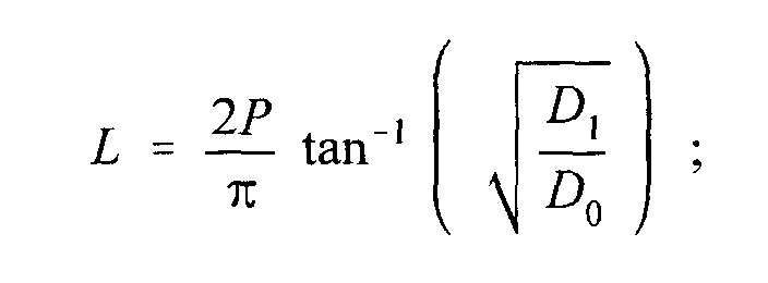
- L
- is the cell length in direction of cutting;
- D1
- is a depth of a cell; and
- D0
- is the amplitude of a sine wave (to be derived from user inputs) minus the depth of the cell.
- The system as recited in claim 18 wherein said amount of ink comprises a volume of ink.
- The system as recited in any one of the claims 17 through 26; said system further comprising:a printer having an ink well; an engraved cylinder (10) rotatably mounted on said printer, said engraved cylinder having a plurality of cells (70, 76) forming a cylinder layout;means located in said computer for determining an ink volume required by at least a portion of the engraved cylinder (10) during a printing process;said means comprising generating means for generating a set of data corresponding to said composite cylinder layout (25) and representing the volumes of the engraved cells which layout is input into said computer, and also for using said set of data to predict said ink volume in order to manage ink filled in said ink well.
Applications Claiming Priority (3)
| Application Number | Priority Date | Filing Date | Title |
|---|---|---|---|
| US08/097,061 US5402246A (en) | 1993-07-20 | 1993-07-20 | Method for predicting ink consumption |
| US97061 | 1993-07-20 | ||
| PCT/US1994/006988 WO1995003668A1 (en) | 1993-07-20 | 1994-06-20 | Method for predicting ink consumption |
Publications (3)
| Publication Number | Publication Date |
|---|---|
| EP0712557A1 EP0712557A1 (en) | 1996-05-22 |
| EP0712557A4 EP0712557A4 (en) | 1996-08-28 |
| EP0712557B1 true EP0712557B1 (en) | 2001-08-29 |
Family
ID=22260711
Family Applications (1)
| Application Number | Title | Priority Date | Filing Date |
|---|---|---|---|
| EP94923217A Expired - Lifetime EP0712557B1 (en) | 1993-07-20 | 1994-06-20 | Method and system for predicting ink consumption |
Country Status (4)
| Country | Link |
|---|---|
| US (2) | US5402246A (en) |
| EP (1) | EP0712557B1 (en) |
| DE (1) | DE69428121T2 (en) |
| WO (1) | WO1995003668A1 (en) |
Families Citing this family (11)
| Publication number | Priority date | Publication date | Assignee | Title |
|---|---|---|---|---|
| US5663803A (en) * | 1993-02-25 | 1997-09-02 | Ohio Electronic Engravers, Inc. | Engraving method and apparatus for engraving areas using a shaping signal |
| US5831746A (en) * | 1993-02-25 | 1998-11-03 | Ohio Electronic Engravers, Inc. | Engraved area volume measurement system and method using pixel data |
| JPH07125255A (en) * | 1993-09-13 | 1995-05-16 | Canon Inc | Image recording apparatus, method thereof, and facsimile apparatus |
| US5592298A (en) * | 1994-06-03 | 1997-01-07 | Xerox Corporation | Apparatus and method for detecting digitized image area coverage by counting pixels |
| US6048446A (en) * | 1997-10-24 | 2000-04-11 | R.R. Donnelley & Sons Company | Methods and apparatuses for engraving gravure cylinders |
| US5947020A (en) * | 1997-12-05 | 1999-09-07 | Ohio Electronic Engravers, Inc. | System and method for engraving a plurality of engraved areas defining different screens |
| DE19805179B4 (en) * | 1998-02-10 | 2005-03-10 | Hell Gravure Systems Gmbh | Method for engraving printing forms |
| US6563605B1 (en) | 1998-02-20 | 2003-05-13 | R. R. Donnelley & Sons Company | Methods of determining gravure cylinder parameters |
| DE19826810A1 (en) * | 1998-06-16 | 1999-12-23 | Koenig & Bauer Ag | Method and device for ink supply |
| KR100739446B1 (en) * | 2005-05-04 | 2007-07-13 | 주식회사 모든박스 | 3D stereoscopic conversion system and method |
| US7546048B2 (en) * | 2006-01-12 | 2009-06-09 | Sun Chemical Corporation | Method for determining ink usage efficiency in commercial printing processes using pigments and quantitative tests |
Family Cites Families (15)
| Publication number | Priority date | Publication date | Assignee | Title |
|---|---|---|---|---|
| US3918348A (en) * | 1973-09-18 | 1975-11-11 | Cross Co | Adaptive control system |
| US3931570A (en) * | 1974-09-19 | 1976-01-06 | Gravure Research Institute, Inc. | Apparatus for measuring cell volume in a gravure printing surface |
| US4003311A (en) * | 1975-08-13 | 1977-01-18 | Bardin Karl D | Gravure printing method |
| US4072928A (en) * | 1975-10-10 | 1978-02-07 | Sangamo Weston, Inc. | Industrial system for inspecting and identifying workpieces |
| JPS5952069B2 (en) * | 1977-12-15 | 1984-12-18 | 凸版印刷株式会社 | Ink usage prediction device |
| US4451856A (en) * | 1979-07-11 | 1984-05-29 | Ohio Electronic Engravers, Inc. | Engraving and scanning apparatus |
| US4628728A (en) * | 1986-02-21 | 1986-12-16 | Wilson Engraving Company, Inc. | Method for measuring the volumetric capacity of anilox rolls |
| DE3617714A1 (en) * | 1986-05-27 | 1987-12-03 | Hell Rudolf Dr Ing Gmbh | VOLUME MEASUREMENT METHOD FOR SURFACE DEPTHS |
| DE3724256A1 (en) * | 1987-07-22 | 1989-02-02 | Hell Rudolf Dr Ing Gmbh | FUNCTIONALITY OF A CIRCUIT ARRANGEMENT FOR THE OPERATION OF ENGRAVING SYSTEMS FOR THE ENGRAVING OF PRINTING FORMS |
| US5029011A (en) * | 1990-04-13 | 1991-07-02 | Ohio Electronic Engravers, Inc. | Engraving apparatus with oscillatory movement of tool support shaft monitored and controlled to reduce drift and vibration |
| US5293426A (en) * | 1990-05-25 | 1994-03-08 | R. R. Donnelley & Sons Company | Printing cylinder engraver calibration system and method |
| IT1256844B (en) * | 1992-06-08 | 1995-12-21 | Olivetti & Co Spa | METHOD AND DEVICE FOR THE RECOGNITION OF THE END-INK IN AN INK-JET PRINT HEAD. |
| JP2839995B2 (en) * | 1992-10-14 | 1998-12-24 | キヤノン株式会社 | Recording device |
| US5438864A (en) * | 1993-08-25 | 1995-08-08 | Praxair S.T. Technology, Inc. | Method for fluorescent measuring the volumetric capacity of a cell-engraved surface |
| US5387976A (en) * | 1993-10-29 | 1995-02-07 | Hewlett-Packard Company | Method and system for measuring drop-volume in ink-jet printers |
-
1993
- 1993-07-20 US US08/097,061 patent/US5402246A/en not_active Ceased
-
1994
- 1994-06-20 WO PCT/US1994/006988 patent/WO1995003668A1/en not_active Ceased
- 1994-06-20 EP EP94923217A patent/EP0712557B1/en not_active Expired - Lifetime
- 1994-06-20 DE DE69428121T patent/DE69428121T2/en not_active Expired - Fee Related
-
1997
- 1997-03-28 US US08/828,321 patent/USRE35911E/en not_active Expired - Lifetime
Also Published As
| Publication number | Publication date |
|---|---|
| US5402246A (en) | 1995-03-28 |
| DE69428121T2 (en) | 2002-03-21 |
| WO1995003668A1 (en) | 1995-02-02 |
| DE69428121D1 (en) | 2001-10-04 |
| EP0712557A4 (en) | 1996-08-28 |
| USRE35911E (en) | 1998-09-29 |
| EP0712557A1 (en) | 1996-05-22 |
Similar Documents
| Publication | Publication Date | Title |
|---|---|---|
| RU2130384C1 (en) | Device for detection of errors and method for engraving | |
| EP0739272B1 (en) | Error detection apparatus and method for use with engravers | |
| US5438422A (en) | Error detection apparatus and method for use with engravers | |
| EP0805957B1 (en) | Intaglio engraving method and apparatus | |
| US6840721B2 (en) | Process for producing dies | |
| US6614558B1 (en) | Engraver and method for focusing and measuring areas on a workpiece engraved by the engraver | |
| US5402246A (en) | Method for predicting ink consumption | |
| EP0164764A2 (en) | Engraving apparatus and method | |
| JP4216355B2 (en) | System and method for measuring volume of engraved area | |
| EP1642712B1 (en) | Platemaking method and platemaking apparatus | |
| US4181077A (en) | Preparation of printing surfaces | |
| EP0082644B1 (en) | Apparatus for measuring the area of image portion of image-bearing member | |
| US6362899B1 (en) | Error detection apparatus and method for use with engravers | |
| EP0812265A1 (en) | Engraving method and apparatus using midtone correction | |
| EP2204283B1 (en) | Plate-making apparatus and printing plate manufacturing method | |
| US20020135811A1 (en) | Error detection apparatus and method for use with engravers | |
| WO1999061247A1 (en) | Engraving system and method comprising improved imaging | |
| US6643033B2 (en) | Methods of determining gravure cylinder parameters | |
| JP3537544B2 (en) | Gravure engraving system | |
| JP4043766B2 (en) | Doctor blade replacement time prediction system | |
| JPH06265473A (en) | Light and shade distribution measuring device | |
| JPH03195912A (en) | Measuring apparatus for pattern area rate | |
| JPH11216951A (en) | Gradation correction method of ablation type image forming material and image forming method employing this | |
| JPH06143534A (en) | Gravure photoengraving output device |
Legal Events
| Date | Code | Title | Description |
|---|---|---|---|
| PUAI | Public reference made under article 153(3) epc to a published international application that has entered the european phase |
Free format text: ORIGINAL CODE: 0009012 |
|
| 17P | Request for examination filed |
Effective date: 19951229 |
|
| AK | Designated contracting states |
Kind code of ref document: A1 Designated state(s): BE CH DE LI |
|
| A4 | Supplementary search report drawn up and despatched |
Effective date: 19960712 |
|
| AK | Designated contracting states |
Kind code of ref document: A4 Designated state(s): BE CH DE LI |
|
| 17Q | First examination report despatched |
Effective date: 19980513 |
|
| RTI1 | Title (correction) |
Free format text: METHOD AND SYSTEM FOR PREDICTING INK CONSUMPTION |
|
| GRAG | Despatch of communication of intention to grant |
Free format text: ORIGINAL CODE: EPIDOS AGRA |
|
| RTI1 | Title (correction) |
Free format text: METHOD AND SYSTEM FOR PREDICTING INK CONSUMPTION |
|
| RTI1 | Title (correction) |
Free format text: METHOD AND SYSTEM FOR PREDICTING INK CONSUMPTION |
|
| GRAG | Despatch of communication of intention to grant |
Free format text: ORIGINAL CODE: EPIDOS AGRA |
|
| GRAH | Despatch of communication of intention to grant a patent |
Free format text: ORIGINAL CODE: EPIDOS IGRA |
|
| RIN1 | Information on inventor provided before grant (corrected) |
Inventor name: STUVE, JULI ANN Inventor name: SEITZ, DAVID R. |
|
| GRAH | Despatch of communication of intention to grant a patent |
Free format text: ORIGINAL CODE: EPIDOS IGRA |
|
| RAP1 | Party data changed (applicant data changed or rights of an application transferred) |
Owner name: MDC MAX DAETWYLER AG BLEIENBACH |
|
| GRAA | (expected) grant |
Free format text: ORIGINAL CODE: 0009210 |
|
| AK | Designated contracting states |
Kind code of ref document: B1 Designated state(s): BE CH DE LI |
|
| PG25 | Lapsed in a contracting state [announced via postgrant information from national office to epo] |
Ref country code: BE Free format text: LAPSE BECAUSE OF FAILURE TO SUBMIT A TRANSLATION OF THE DESCRIPTION OR TO PAY THE FEE WITHIN THE PRESCRIBED TIME-LIMIT Effective date: 20010829 |
|
| REG | Reference to a national code |
Ref country code: CH Ref legal event code: NV Representative=s name: KELLER & PARTNER PATENTANWAELTE AG Ref country code: CH Ref legal event code: EP |
|
| REF | Corresponds to: |
Ref document number: 69428121 Country of ref document: DE Date of ref document: 20011004 |
|
| PGFP | Annual fee paid to national office [announced via postgrant information from national office to epo] |
Ref country code: CH Payment date: 20020618 Year of fee payment: 9 |
|
| PLBE | No opposition filed within time limit |
Free format text: ORIGINAL CODE: 0009261 |
|
| STAA | Information on the status of an ep patent application or granted ep patent |
Free format text: STATUS: NO OPPOSITION FILED WITHIN TIME LIMIT |
|
| 26N | No opposition filed | ||
| PG25 | Lapsed in a contracting state [announced via postgrant information from national office to epo] |
Ref country code: LI Free format text: LAPSE BECAUSE OF NON-PAYMENT OF DUE FEES Effective date: 20030630 Ref country code: CH Free format text: LAPSE BECAUSE OF NON-PAYMENT OF DUE FEES Effective date: 20030630 |
|
| REG | Reference to a national code |
Ref country code: CH Ref legal event code: PL |
|
| PGFP | Annual fee paid to national office [announced via postgrant information from national office to epo] |
Ref country code: DE Payment date: 20090526 Year of fee payment: 16 |
|
| PG25 | Lapsed in a contracting state [announced via postgrant information from national office to epo] |
Ref country code: DE Free format text: LAPSE BECAUSE OF NON-PAYMENT OF DUE FEES Effective date: 20110101 |