EP0712499B1 - Systeme perfectionne de ligne de tube a garnissage avec affichage en temps reel en surface - Google Patents
Systeme perfectionne de ligne de tube a garnissage avec affichage en temps reel en surface Download PDFInfo
- Publication number
- EP0712499B1 EP0712499B1 EP94924562A EP94924562A EP0712499B1 EP 0712499 B1 EP0712499 B1 EP 0712499B1 EP 94924562 A EP94924562 A EP 94924562A EP 94924562 A EP94924562 A EP 94924562A EP 0712499 B1 EP0712499 B1 EP 0712499B1
- Authority
- EP
- European Patent Office
- Prior art keywords
- wireline
- tube
- bore
- tool
- conductor
- Prior art date
- Legal status (The legal status is an assumption and is not a legal conclusion. Google has not performed a legal analysis and makes no representation as to the accuracy of the status listed.)
- Expired - Lifetime
Links
- 239000004020 conductor Substances 0.000 claims abstract description 68
- 238000000034 method Methods 0.000 claims abstract description 10
- 230000015572 biosynthetic process Effects 0.000 claims description 27
- 239000002184 metal Substances 0.000 claims description 10
- 229910052751 metal Inorganic materials 0.000 claims description 10
- 238000009413 insulation Methods 0.000 claims description 7
- 230000000694 effects Effects 0.000 claims description 6
- 229920000642 polymer Polymers 0.000 claims 2
- 239000007787 solid Substances 0.000 abstract description 5
- IJGRMHOSHXDMSA-UHFFFAOYSA-N Atomic nitrogen Chemical compound N#N IJGRMHOSHXDMSA-UHFFFAOYSA-N 0.000 description 10
- 238000012360 testing method Methods 0.000 description 8
- 238000004519 manufacturing process Methods 0.000 description 7
- 238000012856 packing Methods 0.000 description 7
- 229910052757 nitrogen Inorganic materials 0.000 description 5
- 230000006835 compression Effects 0.000 description 4
- 238000007906 compression Methods 0.000 description 4
- 239000004593 Epoxy Substances 0.000 description 3
- 229910045601 alloy Inorganic materials 0.000 description 3
- 239000000956 alloy Substances 0.000 description 3
- 239000012530 fluid Substances 0.000 description 3
- 239000010935 stainless steel Substances 0.000 description 3
- 229910001220 stainless steel Inorganic materials 0.000 description 3
- 230000005540 biological transmission Effects 0.000 description 2
- 238000009954 braiding Methods 0.000 description 2
- 230000006870 function Effects 0.000 description 2
- 239000000463 material Substances 0.000 description 2
- 238000007789 sealing Methods 0.000 description 2
- XLYOFNOQVPJJNP-UHFFFAOYSA-N water Substances O XLYOFNOQVPJJNP-UHFFFAOYSA-N 0.000 description 2
- RYGMFSIKBFXOCR-UHFFFAOYSA-N Copper Chemical compound [Cu] RYGMFSIKBFXOCR-UHFFFAOYSA-N 0.000 description 1
- 239000004952 Polyamide Substances 0.000 description 1
- BQCADISMDOOEFD-UHFFFAOYSA-N Silver Chemical compound [Ag] BQCADISMDOOEFD-UHFFFAOYSA-N 0.000 description 1
- 239000004809 Teflon Substances 0.000 description 1
- 229920006362 Teflon® Polymers 0.000 description 1
- 230000002411 adverse Effects 0.000 description 1
- 239000004760 aramid Substances 0.000 description 1
- 229920003235 aromatic polyamide Polymers 0.000 description 1
- 230000000712 assembly Effects 0.000 description 1
- 238000000429 assembly Methods 0.000 description 1
- 230000007797 corrosion Effects 0.000 description 1
- 238000005260 corrosion Methods 0.000 description 1
- 230000005484 gravity Effects 0.000 description 1
- 239000004519 grease Substances 0.000 description 1
- 229910001293 incoloy Inorganic materials 0.000 description 1
- 238000009434 installation Methods 0.000 description 1
- 230000002452 interceptive effect Effects 0.000 description 1
- 238000005259 measurement Methods 0.000 description 1
- 230000003472 neutralizing effect Effects 0.000 description 1
- 229920002647 polyamide Polymers 0.000 description 1
- 230000002028 premature Effects 0.000 description 1
- 238000002360 preparation method Methods 0.000 description 1
- 238000011084 recovery Methods 0.000 description 1
- 239000011347 resin Substances 0.000 description 1
- 229920005989 resin Polymers 0.000 description 1
- 229910052709 silver Inorganic materials 0.000 description 1
- 239000004332 silver Substances 0.000 description 1
- 238000005476 soldering Methods 0.000 description 1
- 230000006641 stabilisation Effects 0.000 description 1
- 238000011105 stabilization Methods 0.000 description 1
- 239000000725 suspension Substances 0.000 description 1
- 238000003466 welding Methods 0.000 description 1
Images
Classifications
-
- E—FIXED CONSTRUCTIONS
- E21—EARTH OR ROCK DRILLING; MINING
- E21B—EARTH OR ROCK DRILLING; OBTAINING OIL, GAS, WATER, SOLUBLE OR MELTABLE MATERIALS OR A SLURRY OF MINERALS FROM WELLS
- E21B47/00—Survey of boreholes or wells
- E21B47/12—Means for transmitting measuring-signals or control signals from the well to the surface, or from the surface to the well, e.g. for logging while drilling
-
- E—FIXED CONSTRUCTIONS
- E21—EARTH OR ROCK DRILLING; MINING
- E21B—EARTH OR ROCK DRILLING; OBTAINING OIL, GAS, WATER, SOLUBLE OR MELTABLE MATERIALS OR A SLURRY OF MINERALS FROM WELLS
- E21B17/00—Drilling rods or pipes; Flexible drill strings; Kellies; Drill collars; Sucker rods; Cables; Casings; Tubings
- E21B17/02—Couplings; joints
- E21B17/023—Arrangements for connecting cables or wirelines to downhole devices
-
- E—FIXED CONSTRUCTIONS
- E21—EARTH OR ROCK DRILLING; MINING
- E21B—EARTH OR ROCK DRILLING; OBTAINING OIL, GAS, WATER, SOLUBLE OR MELTABLE MATERIALS OR A SLURRY OF MINERALS FROM WELLS
- E21B17/00—Drilling rods or pipes; Flexible drill strings; Kellies; Drill collars; Sucker rods; Cables; Casings; Tubings
- E21B17/02—Couplings; joints
- E21B17/028—Electrical or electro-magnetic connections
- E21B17/0285—Electrical or electro-magnetic connections characterised by electrically insulating elements
-
- E—FIXED CONSTRUCTIONS
- E21—EARTH OR ROCK DRILLING; MINING
- E21B—EARTH OR ROCK DRILLING; OBTAINING OIL, GAS, WATER, SOLUBLE OR MELTABLE MATERIALS OR A SLURRY OF MINERALS FROM WELLS
- E21B17/00—Drilling rods or pipes; Flexible drill strings; Kellies; Drill collars; Sucker rods; Cables; Casings; Tubings
- E21B17/20—Flexible or articulated drilling pipes, e.g. flexible or articulated rods, pipes or cables
- E21B17/206—Flexible or articulated drilling pipes, e.g. flexible or articulated rods, pipes or cables with conductors, e.g. electrical, optical
-
- E—FIXED CONSTRUCTIONS
- E21—EARTH OR ROCK DRILLING; MINING
- E21B—EARTH OR ROCK DRILLING; OBTAINING OIL, GAS, WATER, SOLUBLE OR MELTABLE MATERIALS OR A SLURRY OF MINERALS FROM WELLS
- E21B19/00—Handling rods, casings, tubes or the like outside the borehole, e.g. in the derrick; Apparatus for feeding the rods or cables
- E21B19/22—Handling reeled pipe or rod units, e.g. flexible drilling pipes
-
- E—FIXED CONSTRUCTIONS
- E21—EARTH OR ROCK DRILLING; MINING
- E21B—EARTH OR ROCK DRILLING; OBTAINING OIL, GAS, WATER, SOLUBLE OR MELTABLE MATERIALS OR A SLURRY OF MINERALS FROM WELLS
- E21B23/00—Apparatus for displacing, setting, locking, releasing or removing tools, packers or the like in boreholes or wells
- E21B23/14—Apparatus for displacing, setting, locking, releasing or removing tools, packers or the like in boreholes or wells for displacing a cable or a cable-operated tool, e.g. for logging or perforating operations in deviated wells
-
- E—FIXED CONSTRUCTIONS
- E21—EARTH OR ROCK DRILLING; MINING
- E21B—EARTH OR ROCK DRILLING; OBTAINING OIL, GAS, WATER, SOLUBLE OR MELTABLE MATERIALS OR A SLURRY OF MINERALS FROM WELLS
- E21B47/00—Survey of boreholes or wells
- E21B47/10—Locating fluid leaks, intrusions or movements
- E21B47/117—Detecting leaks, e.g. from tubing, by pressure testing
-
- G—PHYSICS
- G01—MEASURING; TESTING
- G01V—GEOPHYSICS; GRAVITATIONAL MEASUREMENTS; DETECTING MASSES OR OBJECTS; TAGS
- G01V11/00—Prospecting or detecting by methods combining techniques covered by two or more of main groups G01V1/00 - G01V9/00
- G01V11/002—Details, e.g. power supply systems for logging instruments, transmitting or recording data, specially adapted for well logging, also if the prospecting method is irrelevant
Definitions
- the invention relates to an apparatus and method for applying a conventional slick line assembly and a single conductor wireline in combination to obtain "real-time" surface display from well logging tools.
- Measuring instruments or tools are commonly lowered down a wellbore and located in a subterranean reservoir to measure formation characteristics such as bottom hole pressures and temperatures as a function of time. These instruments are available in "memory” type and “real-time” type configurations.
- the "memory” type tools are conventionally lowered through a tubing string positioned in a wellbore on a 3.17 mm (1/8 inch) diameter solid wire called a wireline. This economical and successful procedure and its associated equipment is known as a slick line system and is used mainly for bottom hole pressure testing. These "memory" type tools remain downhole recording data onto a downhole chart for a finite time period. The tool is then retrieved to ascertain the measured data accumulated over the entire period.
- the slick line system is popular due to its minimum equipment requirements and its ease of use.
- the operator of the slick line system can usually estimate the length of time required for the tool to remain downhole and obtain the desired data. If, however, the tool is retrieved prematurely, the data could be incomplete and therefore of questionable value. Conversely, valuable time is lost and needless expense incurred if the tool is left downhole longer than necessary. For example, in the case of a pressure drawdown/build-up test, the tool may be left in the well for a number of days with the expectation that the pressure build-up will have stabilized by the time the tool is recovered - however stabilization may not yet have been achieved.
- “Real-time” type tools both avoid the time uncertainties of the "memory” type tools and supply the operators with data at the surface as it is generated. Signals are generated at the reservoir-located tool and are transmitted up a conductive wireline to a surface-located data acquisition system.
- the wireline is generally comprised of a single conductor and is implemented in a variety of forms requiring various degrees of specialized equipment not in common with the slick line system.
- One form of the conductive wireline is a 1/4" tube within which is located a single, solid electrical conductor.
- the conductor is typically bonded within the bore of the tubing with epoxy or teflon, thereby insulating the conductor therefrom.
- the tubing extends through the wellhead and into the wellbore.
- the tubing is strapped to the outside of the tubing string and extends downwards to the tool which is typically mounted to the bottom of the tubing string.
- the bonded tube, conductor and epoxy insulation are unforgiving with respect to flexing or thermal exposure and are particularly prone to damage.
- Flexing occurs whenever the 6.35 mm (1/4 inch) conductive wireline is installed or removed.
- the wireline is usually spooled onto a large diameter (>182.878 cm (6 ft) diameter) drum.
- 6 ft 6 ft diameter
- each of the tubing, the insulation, and the conductor components are laying at differing physical lengths of circumference. This varying pitch results in differential movement of each component and repeated deformation.
- differential thermal expansion and relative movement occurs when the tubing changes temperature with respect to the conductor.
- Multiple use and re-use of the wireline results in eventual failure of the conductor, the insulation or both, resulting in permanent damage to the wireline. For these reasons, handling of the tubing, or differential thermal expansion experienced in the wellbore often result in irreparable damage to the expensive assembly.
- Both of the 6.35 mm (1/4 inch) tubing and conductor wirelines are generally used in permanent installations. Each of them require tripping of the tubing string to repair or change the tool. The production delay or suspension of a well operation to trip tubing from a well can be expensive. Further, a rig is required at the well to effect the removal of the tubing string. Still further, significantly larger scale wireline spool and associated equipment is required than is used in the slick line system.
- one or more insulated conductors are contained within a flexible and conductive braided outer sheath.
- the braided wireline and an attached tool can be run into and removed from the bore of a tubing string without requiring the removal of the tubing string.
- Braided wirelines of diameters less than 4.762 (3/16 inch) for one conductor) are not known to the inventor.
- the tool is introduced to the tubing string through an isolating lubricator mounted at the wellhead.
- the braided wireline requires significant effort and specialized equipment to seal it at the lubricator. Typically an extra person is required, dedicated to managing a pressurized grease sealing system.
- the braiding conforms in length to the conductor length, being more robust and suited to multiple use than are the 6.35 mm (1/4 inch) tubing and conductor assemblies.
- the braiding is expensive however, and due to the high surface area and the braid's tendency for corrosion, expensive and exotic materials are required when used for sour (H 2 S) service.
- H 2 S sour
- wirelines are amenable to being used with existing slick line equipment in "real-time” testing applications.
- the braided wireline is generally too expensive for use in other than production logging and requires specialized equipment not available with the existing slick line systems.
- the 6.35 mm (1/4 inch) wirelines suffer the following incompatibilities for use with the slick line system: the wireline diameter is too large and too inflexible for spooling onto conventional slick line drums; the wireline is too inflexible to be drawn down into the well under the weight of the attached tools alone, therefore requiring specialized drawworks; and the wireline requires a larger guiding sheave and packing seal at the lubricator.
- An object of the present invention is to provide a conductive wireline amenable for use with conventional slick line equipment currently in popular and widespread use, for obtaining "real-time" surface readout for both bottom hole pressure testing and production logging applications.
- the wireline described in Moore's United States Patent 5,122,209 is provided in a small diameter and flexible form so that it may be used in conjunction with conventional slick line equipment to provide means for running a logging tool through the completion string of a well to measure a subterranean formation characteristic (such as reservoir pressure or resistivity) and provide "real-time" surface display thereof.
- a subterranean formation characteristic such as reservoir pressure or resistivity
- a conductive tubing is provided that can function as a conductor in the tool circuit and can bear the weight of the tool, yet is also sufficiently flexible to be used with a slick line drum and passed through a slick line lubricator without permanent deformation.
- a conductor that will resist straightening and thus will not break due to its own weight and which can independently elongate and contract and move laterally to accommodate thermal and spooling effects without breakage or shorting.
- the invention in one aspect is a slick line assembly for logging subterranean formation characteristics in conjunction with a well having a wellhead and containing a completion string having an axial bore, comprising: a slick line lubricator mounted on the wellhead; a driven slick line drum positioned adjacent the well and carrying a wireline extending through the lubricator in to the bore of the completion string; said wireline comprising an electrically conductive metal tube forming an internal longitudinal bore, said tube having an outside diameter of about 3.17 mm (1/8 inch) and being sufficiently flexible to be used with the drum and lubricator without being permanently deformed, and a helically formed, multiple strand, thermally and electrically insulated conductor extending through the tube bore and being coextensive with and in frictional contact with the tube wall, said conductor having a diameter smaller than that of the tube bore and being free to move axially therewithin except as restrained by the frictional contact; a formation characteristic measuring tool attached to the bottom of
- the invention comprises a method for logging a subterranean formation characteristic in conjunction with a well, said well having a wellhead, a completion string having an axial bore, and a slick line lubricator mounted on the wellhead, said well further having a driven slick line drum associated with it for feeding wireline into the completion string through the lubricator and withdrawing it, comprising:
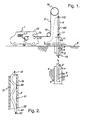
- a slick line assembly 1 comprising a wireline 2 for supporting a logging tool 3 in a well 5 extending into a subterranean formation 6.
- the well 5 comprises a tubing string 4 having an axial bore 10.
- a wellhead 11 is located at the top of the completion string 4 at ground surface 8.
- the slick line assembly 1 further comprises a driven drum 14 of the size and type conventionally used with 3.18 mm - 2.34 mm (.125-.092 inch) solid wireline.
- the wireline 2 is spooled on the drum 14 and extends through rollers 15 and over sheaves 16 to the top of a lubricator 9.
- the lubricator 9 enables the tool 3 and the wireline 2 to be inserted and removed from the well 5. More particularly, the lubricator 9 forms an upstanding tubular chamber 150 with an isolating valve 17, at its lower end, attached to the existing wellhead 11, and a packing at its upper end.
- the wireline 2 extends through the packing, through the lubricator 9 and into the bore 10 of the tubing string 4.
- a small hydraulic pump 100 pressurizes the packing, enabling it to seal around the wireline 2.
- the wireline 2 comprises a 3.17 mm (1/8 inch) outside diameter, electrically conductive tube 18 formed of stainless steel and having a wall thickness of 0.55 mm (0.022 inches).
- the tube 18 forms an internal longitudinal bore 19.
- a single insulated conductor 20 extends coextensively through the bore 19.
- the conductor 20 is of smaller cross-section than the bore 19 so that an annular space 21 is formed between the insulated conductor 20 and the tube 18.
- two conductive paths 18, 20 are provided, being suitable for transmitting signals from conventional "real-time” logging tools.
- Standard wireline is referred to in the industry as having a single conductor (the insulated conductor 20), the second ground path (the tube 18) being presupposed.
- the insulated conductor 20 is made from stranded 20 gauge silver plated copper wire 22 per ASTM standard B298-74A.
- the conductor has a two part insulation covering 23.
- the primary insulation is provided by two polyamide tapes ("Capton” supplied by Dupont) contrahellically applied to the wire with a minimum 50% overlap on each wrap.
- a secondary topcoat of aromatic polyamide resin is applied to seal the tape and improve durability.
- the diameter of the overall finished conductor 20 is about 1.40 mm ⁇ 0.05 mm (0.055 inch ⁇ 0.002 inch).
- the wireline 2 is first formed by installing the insulated conductor into a 6.35 mm (1/4 inch) tube using a method described in detail in U.S. Patent 5,122,209 issued to Moore. A strip of flat material is formed into the tube whilst simultaneously feeding the insulated conductor 20 thereinto. The insulated conductor 20 is specifically protected during the welding procedure used to seal the longitudinal seam of the tube.
- the tube 18 can be made from stainless steel, or INCOLOY 825 (Huntington Alloys, Huntington, WV.). These alloys can be used in H 2 S service applications due to the non-trapping, clean outer surface of the tube.
- the insulated conductor 20 is provided in a helically coiled condition.
- the insulated conductor 20 is coextensive with and in frictional contact with the inside wall of the tube 18. This contact enables relatively free longitudinal movement to occur between the tube 18 and the conductor 20 as a result of differential thermal growth, yet it frictionally restrains the conductor from straightening and dropping to the bottom of the tubing under gravity loading. Lengths of insulated conductor 20 as long as 6.1 km (20 000 feet) can thus be provided within small diameter tube 18.
- the 6.35 mm (1/4 inch) assembly of tube and conductor 18, 20 is mechanically drawn to a 3.17 mm (1/8 inch) diameter with about a 0.55 mm (0.022 inch) wall for use with the slick line assembly 1.
- Gibson Tube of Bridgewater, New Jersey has tested a suitable drawing technique for this purpose and is commercially supplying 3.17 mm (1/8 inch) diameter tube containing the helically coiled conductor.
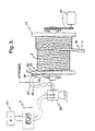
- the wireline 2 is spooled onto the drum 14.
- the drum 14 is driven with a hydraulic drive and transmission means 24.
- the surface end 25 of the wireline projects from the drum 14 and terminates with a compression fitting to a tubing tee connection 26.
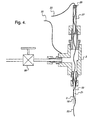
- a connector 27 is connected to the tee 26 and ends with a hermetic seal 28 threaded thereinto, as detailed in Figure 4.
- the hermetic seal 28 enables the insulated conductor 20 to pass straight through and out of the tee 26 while sealing the annular space 21.
- the stem of the tee 26 is fitted with a valve means 99 and, when opened, it permits the annular space 21 of the wireline 2 to be pressurized, preferably with nitrogen.
- the insulated conductor 20 is then directed back to the axis of the drum 14 to a commercial connector ring assembly 29 such as that available from IEC Corporation, Austin Texas, Model IEC-2-GO.
- a ground wire 30 is electrically connected to the tee 26 and is similarly directed to the connector ring assembly 29.
- the connector ring assembly 29 establishes electrical connection from the insulated conductor 20 and ground wire 30, which rotate with the drum 14, to a non-rotating power lead 31 connected with the insulated conductor 20 and to a non-rotating ground lead 32 connected with the conductive tube 18.
- the leads 31, 32 complete an electrical circuit with the logging tools 3 and enable the transmission of generated signals to the recording and display means 7 at ground surface 8.
- the recording and display means 7 is a conventional data acquisition system which is matched to the logging tool 3.
- a power source 101 is provided for energizing the circuit and enabling the tool 3 to generate signals indicative of the formation characteristic for which is it designed.
- the power source 101 is matched to the logging tool 3.
- Computalog of Fort Worth, Texas supplies matching logging tools, power sources (typically 300 V) and display means.
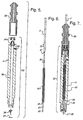
- the cable head adapter 33 comprises a metal body 41, connected to the wireline 2 at its top end with a compression fitting 34.
- the adapter body 41 is hollow, forming a bore 35 into which the insulated conductor 20 extends from the wireline 2.
- the conductor 20 is electrically connected to a plug 36 which is adapted for electrical connection with the logging tool 3.
- the adapter body 41 electrically grounds to the tool.
- the plug 36 is detachably secured to the bottom end of the adapter body 41 with a mechanical retaining means 37.
- a fishneck 38 is attached to the top of the adapter 33 to facilitate retrieval of the tool 3 if lost down the well 5.
- the tube 18 can elongate, due to thermal effects, at a faster rate than the conductor 20.
- the conductor 20 could be drawn completely within the tube 18, straining and breaking the connection to the plug 36. Therefore, approximately 1.5 m (5 feet) of the bottom of the insulated conductor 20 is formed into a tight coil 42 about 15.24 cm (6 inch) in length, which provides an excess length of conductor and enables the conductor 20 to remain coextensive with the tube 18.
- the wireline annulus 21 is left open to the inside bore 35 of the adapter 33, which is filled with a non-conductive fluid 39, such as that used in electrical transformers, injected through a side port 40. Should a leak occur in the wireline 2, oil or water is unable to displace the heavy non-conductive fluid 39 and adversely affect the electrical connection at the plug 36. In this way, a leak will not force a premature end to the testing. Once a test is complete, the lead can be repaired and the annular space 21 blown clear and dried out with nitrogen without permanent damage.
- a non-conductive fluid 39 such as that used in electrical transformers
- the wireline 2 can be readily pressure tested with nitrogen prior to each use by using the valve means 99 and tee 36. Leaks can be detected using a water bath and bubble technique and repaired by soldering.
- the slick line assembly 1 and its wireline 2 are positioned adjacent the well 5 and a length of wireline is unspooled from the drum.
- the logging tool 3 is connected to the cable head adapter 33.
- the wireline and tool assembly 2, 3 is installed into the lubricator 9 and the packing 8 secured thereto.
- the hydraulic pump 100 seals the packing around the wireline and the isolating valve 17 is opened to the tubing string 4. Note that this may be accomplished without interfering with the production or other operation of the well.
- valve means 99 is opened and the annulus 21 of the wireline 2 is pressurized from a nitrogen source.
- the valve means 99 is closed, the nitrogen source is removed, and the drum 14 is freed for rotation.
- the tool 3 is lowered through the bore 10 of the completion string 4 by unspooling the wireline 2 from the drum to traverse the formation 6.
- the weight of the attached tool is sufficient to draw the wireline down with the tool.
- the circuit is energized when the tool is opposite the formation or portion of the well of interest.
- the logging tool 3 measures the particular characteristics of the formation 6 for which it is designed and emits signals indicative of the measurements, which signals are transmitted through the wireline 2.
- the recording and receiving means 7 at the ground surface receives and records the signals from the wireline 2.
- the wireline 2 and attached tool 3 are withdrawn from the well 4 by spooling the wireline 2 onto the drum 14 to raise the tool for recovery in the lubricator 9.
- the invention has been found to be characterized by the following advantages:
Landscapes
- Engineering & Computer Science (AREA)
- Life Sciences & Earth Sciences (AREA)
- Geology (AREA)
- Mining & Mineral Resources (AREA)
- Physics & Mathematics (AREA)
- General Life Sciences & Earth Sciences (AREA)
- Environmental & Geological Engineering (AREA)
- Fluid Mechanics (AREA)
- Geochemistry & Mineralogy (AREA)
- Mechanical Engineering (AREA)
- Geophysics (AREA)
- General Physics & Mathematics (AREA)
- Remote Sensing (AREA)
- Geophysics And Detection Of Objects (AREA)
- Earth Drilling (AREA)
- Insulated Conductors (AREA)
- Road Signs Or Road Markings (AREA)
- Farming Of Fish And Shellfish (AREA)
- Measurement And Recording Of Electrical Phenomena And Electrical Characteristics Of The Living Body (AREA)
Claims (8)
- Assemblage de tube à garnissage pour l'enregistrement diagraphique des caractéristiques d'une formation souterraine, comprenant un puits (5) comportant une tête de puits (1) et contenant un train de complétion (4) comportant un alésage axial (10), l'assemblage comprenant en outre:un lubrificateur du tube à garnissage (9) monté sur la tête du puits (11);un tambour entraíné du tube à garnissage (14) positionné près du puits (5) et supportant un câble métallique s'étendant à travers le lubrificateur (9) dans l'alésage (10) du train de complétion (4);ledit câble métallique comprenant un tube métallique conducteur d'électricité (18) formant un alésage longitudinal interne (19), ledit tube métallique (18) comportant une soudure et ayant un diamètre extérieur d'environ 3,17 mm (1/8 pouce) et une épaisseur de paroi sélectionnée de sorte à correspondre à une valeur de l'ordre de 0,55 mm (0,022 pouce), pour former un tube suffisamment flexible pour être enroulé sur le tambour du tube à garnissage (14) et pour être utilisé avec le lubrificateur (9) sans déformation permanente, un conducteur électrique hélicoïdal à plusieurs torons, à isolation thermique et électrique (20) s'étendant à travers l'alésage du tube (19) et s'étendant avec la paroi du tube et étant en contact par frottement avec celle-ci, ledit conducteur isolé (20) ayant un diamètre inférieur à celui de l'alésage du tube (19) et pouvant se déplacer librement dans une direction axiale dans celui-ci, à l'exception de la restriction établie par le contact par frottement;un outil de mesure des caractéristiques de la formation (3) fixé sur la partie inférieure du câble métallique (2) et connecté en service au tube (18) et au conducteur (20) pour former un circuit, ledit outil (3) étant positionné dans l'alésage du train de complétion (10) pour être remonté et descendu à travers celui-ci, ledit outil (3) étant destiné, lors de son actionnement, à émettre des signaux indicatifs des caractéristiques de la formation;une source d'énergie (101) pour exciter le circuit; etun moyen (7) au niveau de la surface du sol destiné à recevoir les signaux émis et à les afficher.
- Assemblage selon la revendication 1, dans lequel le conducteur (20) est enroulé de manière relativement dense au niveau de son extrémité inférieure pour établir une longueur supplémentaire pour que le conducteur (20) puise toujours s'étendre avec le tube (18) au cas où le tube serait allongé davantage que le conducteur (20) par suite d'effets thermiques.
- Assemblage selon l'une quelconque des revendications précédentes, dans lequel l'isolation du conducteur (20) est composée d'un polymère.
- Assemblage selon la revendication 3, dans lequel le polymère est un polyamide.
- Assemblage selon l'une quelconque des revendications précédentes, dans lequel le diamètre du conducteur isolé (20) correspond à environ 1,40 mm (0,055 pouce).
- Assemblage selon l'une quelconque des revendications précédentes, comprenant en outre un moyen au niveau de la surface du sol pour mettre sous pression l'alésage (19) du tube métallique (18) pour égaliser au moins partiellement la pression dans l'alésage (19) avec la pression à l'extérieur du tube (18).
- Procédé d'enregistrement diagraphique des caractéristiques d'une formation dans un puits (5), ledit puits (5) comportant une tête de puits (11), un train de complétion (4) comportant un alésage axial (10) et un lubrificateur de tube à garnissage (9) monté sur la tête de puits (11), ledit puits (5) comportant en outre un tambour entraíné du tube à garnissage (14) qui y est associé pour amener un câble métallique (2) dans le train de complétion (4) à travers le lubrificateur (9) et pour le retirer de celui-ci, comprenant les étapes ci-dessous:fourniture d'un câble métallique flexible (2) comprenant un tube métallique conducteur (18) comportant une soudure et ayant un diamètre extérieur de l'ordre de 3,17 mm (1/8 pouce) et une épaisseur de paroi correspondant à environ 0,55 mm (0,022 pouce) pour former un tube suffisamment flexible pour être enroulé sur le tambour du tube à garnissage (14), le tube métallique (18) comportant un alésage longitudinal interne (19) ayant un diamètre intérieur, et un fil conducteur à isolation thermique et électrique (20) ayant un diamètre s'étendant à travers l'alésage du tube (19), ledit diamètre intérieur étant supérieur au diamètre dudit fil conducteur isolé, de sorte à former un espace annulaire (21) entre le tube métallique (18) et le fil conducteur isolé (20), le câble métallique (2) étant enroulé sur le tambour (4) et s'étendant à travers le lubrificateur dans l'alésage du train de complétion (10);agencement d'un outil de mesure des caractéristiques de la formation (3) dans l'alésage du train de complétion (10), ledit outil (3) étant fixé sur l'extrémité inférieure du câble métallique (2) et étant connecté en service au tube métallique (18) et au fil conducteur isolé (20) de sorte à former un circuit pour actionner l'outil (3), pour l'entraíner à émettre des signaux indicatifs des caractéristiques de la formation et à transmettre les signaux vers la surface du sol;fourniture d'une source d'énergie (101) pour exciter le circuit;fourniture d'un moyen (7) au niveau de la surface du sol pour enregistrer les signaux émis par l'outil (3);descente de l'outil (3) à travers l'alésage du train de complétion (10) sur le câble métallique (2) en vue de la traversée de la formation;excitation du circuit lorsqu'il et opposé à la formation pour entraíner la transmission des signaux indicatifs des caractéristiques de la formation à travers le câble métallique (2);enregistrement des signaux transmis; etretrait du câble métallique (2) et de l'outil (3) du puits (5) en enroulant le câble métallique (2) sur le tambour (14) et en récupérant l'outil (3) dans le lubrificateur (9).
- Procédé selon la revendication 7, dans lequel ledit fil conducteur (20) est un fil conducteur hélicoïdal à plusieurs torons, à isolation thermique et électrique, s'étendant à travers l'alésage du tube (19), ledit fil isolé (20) étant en contact par frottement avec la paroi du tube, et ledit fil conducteur (20) ayant un diamètre notablement inférieur à celui de l'alésage du tube (19), de sorte que le fil isolé (20) peut se déplacer librement dans la direction axiale et latérale dans l'alésage (19), à l'exception de la restriction établie par le contact par frottement.
Priority Applications (2)
| Application Number | Priority Date | Filing Date | Title |
|---|---|---|---|
| EP00204686A EP1091084B1 (fr) | 1993-08-02 | 1994-08-02 | Système perfectionné de ligne de tube à garnissage avec affichage en temps réel en surface |
| EP02077164A EP1251242A1 (fr) | 1993-08-02 | 1994-08-02 | Système de ligne de tube à garnissage avec affichage en temps réel en surface |
Applications Claiming Priority (3)
| Application Number | Priority Date | Filing Date | Title |
|---|---|---|---|
| US08/101,321 US5495755A (en) | 1993-08-02 | 1993-08-02 | Slick line system with real-time surface display |
| US101321 | 1993-08-02 | ||
| PCT/US1994/008769 WO1995004290A1 (fr) | 1993-08-02 | 1994-08-02 | Systeme perfectionne de ligne de tube a garnissage avec affichage en temps reel en surface |
Related Child Applications (2)
| Application Number | Title | Priority Date | Filing Date |
|---|---|---|---|
| EP00204686A Division EP1091084B1 (fr) | 1993-08-02 | 1994-08-02 | Système perfectionné de ligne de tube à garnissage avec affichage en temps réel en surface |
| EP02077164A Division EP1251242A1 (fr) | 1993-08-02 | 1994-08-02 | Système de ligne de tube à garnissage avec affichage en temps réel en surface |
Publications (3)
| Publication Number | Publication Date |
|---|---|
| EP0712499A1 EP0712499A1 (fr) | 1996-05-22 |
| EP0712499A4 EP0712499A4 (fr) | 1999-06-09 |
| EP0712499B1 true EP0712499B1 (fr) | 2003-02-26 |
Family
ID=22284035
Family Applications (3)
| Application Number | Title | Priority Date | Filing Date |
|---|---|---|---|
| EP00204686A Expired - Lifetime EP1091084B1 (fr) | 1993-08-02 | 1994-08-02 | Système perfectionné de ligne de tube à garnissage avec affichage en temps réel en surface |
| EP94924562A Expired - Lifetime EP0712499B1 (fr) | 1993-08-02 | 1994-08-02 | Systeme perfectionne de ligne de tube a garnissage avec affichage en temps reel en surface |
| EP02077164A Ceased EP1251242A1 (fr) | 1993-08-02 | 1994-08-02 | Système de ligne de tube à garnissage avec affichage en temps réel en surface |
Family Applications Before (1)
| Application Number | Title | Priority Date | Filing Date |
|---|---|---|---|
| EP00204686A Expired - Lifetime EP1091084B1 (fr) | 1993-08-02 | 1994-08-02 | Système perfectionné de ligne de tube à garnissage avec affichage en temps réel en surface |
Family Applications After (1)
| Application Number | Title | Priority Date | Filing Date |
|---|---|---|---|
| EP02077164A Ceased EP1251242A1 (fr) | 1993-08-02 | 1994-08-02 | Système de ligne de tube à garnissage avec affichage en temps réel en surface |
Country Status (8)
| Country | Link |
|---|---|
| US (1) | US5495755A (fr) |
| EP (3) | EP1091084B1 (fr) |
| CN (1) | CN1053968C (fr) |
| AT (2) | ATE327407T1 (fr) |
| AU (1) | AU7479794A (fr) |
| CA (1) | CA2168651C (fr) |
| DE (2) | DE69432181D1 (fr) |
| WO (1) | WO1995004290A1 (fr) |
Families Citing this family (28)
| Publication number | Priority date | Publication date | Assignee | Title |
|---|---|---|---|---|
| US5495755A (en) * | 1993-08-02 | 1996-03-05 | Moore; Boyd B. | Slick line system with real-time surface display |
| US5907966A (en) | 1996-06-19 | 1999-06-01 | Moore; Boyd B. | Rolled-formed seat and retainer for a fluid-tight ferrule seal on a rigid metal tube which is harder than the ferrule, method and apparatus |
| US5778978A (en) * | 1996-08-06 | 1998-07-14 | Pipe Recovery Services, L.L.P. | Exterior wireline cable adapter sub |
| US5894104A (en) * | 1997-05-15 | 1999-04-13 | Schlumberger Technology Corporation | Coax-slickline cable for use in well logging |
| US6148925A (en) | 1999-02-12 | 2000-11-21 | Moore; Boyd B. | Method of making a conductive downhole wire line system |
| US6318463B1 (en) * | 1999-09-24 | 2001-11-20 | Halliburton Energy Services, Inc. | Slickline fluid indentification tool and method of use |
| US6536519B1 (en) * | 2000-10-13 | 2003-03-25 | Schlumberger Technology Corp. | Downhole tool to generate tension pulses on a slickline |
| US7389183B2 (en) * | 2001-08-03 | 2008-06-17 | Weatherford/Lamb, Inc. | Method for determining a stuck point for pipe, and free point logging tool |
| AU2002323445A1 (en) | 2001-08-29 | 2003-03-18 | Sensor Highway Limited | Method and apparatus for determining the temperature of subterranean wells using fiber optic cable |
| US6995685B2 (en) * | 2001-09-25 | 2006-02-07 | Landis+Gyr, Inc. | Utility meter power arrangements and methods |
| US20040010587A1 (en) * | 2002-07-09 | 2004-01-15 | Arturo Altamirano | Method and apparatus for displaying real time graphical and digital wellbore information responsive to browser initiated client requests via the internet |
| CA2439026C (fr) | 2002-08-30 | 2008-11-25 | Schlumberger Canada Limited | Systeme a fibre optique de transport, de telemesure et/ou de declenchement |
| FR2848363B1 (fr) * | 2002-12-10 | 2005-03-11 | Geoservices | Dispositif de transmission de donnees pour une installation d'exploitation de fluides contenus dans un sous-sol. |
| US20050045343A1 (en) * | 2003-08-15 | 2005-03-03 | Schlumberger Technology Corporation | A Conduit Having a Cable Therein |
| EP2054975B1 (fr) * | 2006-07-28 | 2016-05-11 | Quick Connectors, Inc. | Connecteur électrique pour des fils conducteurs enfermés dans une gaine tubulaire de protection |
| AU2008213928B2 (en) * | 2007-02-05 | 2012-05-17 | Quick Connectors Inc. | Down hole electrical connector for combating rapid decompression |
| US8272260B2 (en) * | 2008-09-18 | 2012-09-25 | Baker Hughes Incorporated | Method and apparatus for formation evaluation after drilling |
| BRPI0922363A2 (pt) * | 2008-12-03 | 2017-06-06 | Ziebel As | método para interromper o vazamento de fluidos de poços a partir de uma haste bobinável de intervenção em poço. |
| US9207423B2 (en) * | 2012-03-22 | 2015-12-08 | Ximedix, Inc. | Repairable fiber optic cable |
| WO2014137335A1 (fr) * | 2013-03-06 | 2014-09-12 | Halliburton Energy Services, Inc. | Câble lisse lié et procédés d'utilisation |
| US20140253341A1 (en) * | 2013-03-11 | 2014-09-11 | Abrado, Inc. | Method and apparatus for communication of wellbore data, including visual images |
| CN104515451A (zh) * | 2014-12-23 | 2015-04-15 | 重庆钰康机械有限公司 | 用于带周向孔汽车配件的快速检测装置 |
| GB201713209D0 (en) | 2017-08-17 | 2017-10-04 | Ziebel As | Well logging assembly |
| CN109025967B (zh) * | 2018-08-31 | 2021-08-17 | 黑龙江省易爱蒽新材料科技发展有限公司 | 一种轻便式、防掉、快脱、防喷管装置 |
| CN110469325B (zh) * | 2019-08-08 | 2022-03-29 | 中国石油天然气股份有限公司 | 一种油气田注气管柱找漏方法 |
| CN112360437A (zh) * | 2020-11-23 | 2021-02-12 | 中国地质科学院岩溶地质研究所 | 一种钻孔雷达天线辅助移动装置 |
| CN116771325B (zh) * | 2023-06-25 | 2024-04-19 | 宁波市电力设计院有限公司 | 一种地层导电性测量仪 |
| US20250232895A1 (en) * | 2024-01-11 | 2025-07-17 | Halliburton Energy Service, Inc | Electric cable with undulated tubing segments for suspension in a well system and method of assembly thereof |
Family Cites Families (37)
| Publication number | Priority date | Publication date | Assignee | Title |
|---|---|---|---|---|
| US1523629A (en) * | 1921-03-28 | 1925-01-20 | Bullock Albert | Well-drilling apparatus |
| US2018477A (en) * | 1932-08-26 | 1935-10-22 | Bell Telephone Labor Inc | Coaxial conductor system |
| US1998826A (en) * | 1933-03-16 | 1935-04-23 | Bell Telephone Labor Inc | Electrical conducting system |
| US2357906A (en) * | 1942-11-02 | 1944-09-12 | Mcgraw Electric Co | Electric resistor unit |
| US2950454A (en) * | 1958-10-30 | 1960-08-23 | Bell Telephone Labor Inc | Helix wave guide |
| NL130387C (fr) * | 1959-12-29 | |||
| US3285629A (en) * | 1963-12-11 | 1966-11-15 | Roy H Cullen | Methods and apparatus for mounting electrical cable in flexible drilling hose |
| US3265803A (en) * | 1964-01-14 | 1966-08-09 | Gar Wood Ind Inc | Flexible electrical cable |
| US3356790A (en) * | 1966-02-18 | 1967-12-05 | Gen Cable Corp | Coaxial cable |
| US3443429A (en) * | 1967-01-09 | 1969-05-13 | Gulf Research Development Co | Apparatus for well treatment and measurement |
| US3916685A (en) * | 1970-10-19 | 1975-11-04 | Hans J Paap | Well logging system and method using an armored coaxial cable and compensation circuit |
| NL7414546A (nl) * | 1973-11-15 | 1975-05-20 | Rhone Poulenc Sa | Soepele verwarmingsbuis en werkwijze voor het vervaardigen ervan. |
| FR2314592A1 (fr) * | 1975-06-12 | 1977-01-07 | Cables De Lyon Geoffroy Delore | Guide d'ondes helicoidal |
| US4137762A (en) * | 1977-03-02 | 1979-02-06 | Smith William D | Wireline apparatus for use in earth boreholes |
| US4095865A (en) * | 1977-05-23 | 1978-06-20 | Shell Oil Company | Telemetering drill string with piped electrical conductor |
| US4121193A (en) * | 1977-06-23 | 1978-10-17 | Shell Oil Company | Kelly and kelly cock assembly for hard-wired telemetry system |
| GB1571677A (en) * | 1978-04-07 | 1980-07-16 | Shell Int Research | Pipe section for use in a borehole |
| US4214693A (en) * | 1978-05-30 | 1980-07-29 | Smith William D | Method of making wireline apparatus for use in earth boreholes |
| FR2446433A1 (fr) * | 1979-01-12 | 1980-08-08 | Commissariat Energie Atomique | Ligne de transmission flexible |
| US4368348A (en) * | 1979-12-21 | 1983-01-11 | Techno-Chemie Kessler & Co. Gmbh | Vacuum cleaner hose with an electrical conductor |
| US4346256A (en) * | 1980-04-01 | 1982-08-24 | Kobe, Inc. | Conduit in supplying electrical power and pressurized fluid to a point in a subterranean well |
| US4416494A (en) * | 1980-10-06 | 1983-11-22 | Exxon Production Research Co. | Apparatus for maintaining a coiled electric conductor in a drill string |
| US4415895A (en) * | 1981-02-11 | 1983-11-15 | Dresser Industries, Inc. | Well logging data transmission system |
| US4547774A (en) * | 1981-07-20 | 1985-10-15 | Optelcom, Inc. | Optical communication system for drill hole logging |
| US4554650A (en) * | 1982-04-02 | 1985-11-19 | The United States Of America As Represented By The Secretary Of The Navy | Oil filled towed array hose without couplings |
| US4552432A (en) * | 1983-04-21 | 1985-11-12 | Cooper Industries, Inc. | Hybrid cable |
| GB2190410B (en) * | 1986-05-16 | 1989-12-06 | Coal Ind | Telemetry system for borehole drilling |
| US4681169A (en) * | 1986-07-02 | 1987-07-21 | Trw, Inc. | Apparatus and method for supplying electric power to cable suspended submergible pumps |
| US4842064A (en) * | 1987-12-22 | 1989-06-27 | Otis Engineering Corporation | Well testing apparatus and methods |
| US5122209A (en) * | 1989-12-18 | 1992-06-16 | Shell Oil Company | Temperature compensated wire-conducting tube and method of manufacture |
| US5234058A (en) * | 1990-03-15 | 1993-08-10 | Conoco Inc. | Composite rod-stiffened spoolable cable with conductors |
| US5080175A (en) * | 1990-03-15 | 1992-01-14 | Williams Jerry G | Use of composite rod-stiffened wireline cable for transporting well tool |
| US5140318A (en) * | 1991-04-12 | 1992-08-18 | Conoco Inc. | Data transmission system for downhole logging tools |
| US5294923A (en) * | 1992-01-31 | 1994-03-15 | Baker Hughes Incorporated | Method and apparatus for relaying downhole data to the surface |
| US5329811A (en) * | 1993-02-04 | 1994-07-19 | Halliburton Company | Downhole fluid property measurement tool |
| US5495755A (en) * | 1993-08-02 | 1996-03-05 | Moore; Boyd B. | Slick line system with real-time surface display |
| US6148925A (en) * | 1999-02-12 | 2000-11-21 | Moore; Boyd B. | Method of making a conductive downhole wire line system |
-
1993
- 1993-08-02 US US08/101,321 patent/US5495755A/en not_active Expired - Lifetime
-
1994
- 1994-08-02 EP EP00204686A patent/EP1091084B1/fr not_active Expired - Lifetime
- 1994-08-02 AT AT00204686T patent/ATE327407T1/de not_active IP Right Cessation
- 1994-08-02 DE DE69432181T patent/DE69432181D1/de not_active Expired - Lifetime
- 1994-08-02 EP EP94924562A patent/EP0712499B1/fr not_active Expired - Lifetime
- 1994-08-02 EP EP02077164A patent/EP1251242A1/fr not_active Ceased
- 1994-08-02 CA CA002168651A patent/CA2168651C/fr not_active Expired - Lifetime
- 1994-08-02 AU AU74797/94A patent/AU7479794A/en not_active Abandoned
- 1994-08-02 WO PCT/US1994/008769 patent/WO1995004290A1/fr not_active Ceased
- 1994-08-02 CN CN94193483A patent/CN1053968C/zh not_active Expired - Fee Related
- 1994-08-02 AT AT94924562T patent/ATE233408T1/de not_active IP Right Cessation
- 1994-08-02 DE DE69434746T patent/DE69434746T2/de not_active Expired - Fee Related
Also Published As
| Publication number | Publication date |
|---|---|
| DE69434746D1 (de) | 2006-06-29 |
| CA2168651A1 (fr) | 1995-02-09 |
| EP1251242A1 (fr) | 2002-10-23 |
| EP0712499A4 (fr) | 1999-06-09 |
| AU7479794A (en) | 1995-02-28 |
| ATE327407T1 (de) | 2006-06-15 |
| DE69432181D1 (de) | 2003-04-03 |
| EP0712499A1 (fr) | 1996-05-22 |
| CN1131465A (zh) | 1996-09-18 |
| ATE233408T1 (de) | 2003-03-15 |
| CA2168651C (fr) | 1997-02-04 |
| DE69434746T2 (de) | 2007-05-03 |
| EP1091084B1 (fr) | 2006-05-24 |
| US5495755A (en) | 1996-03-05 |
| CN1053968C (zh) | 2000-06-28 |
| WO1995004290A1 (fr) | 1995-02-09 |
| EP1091084A1 (fr) | 2001-04-11 |
Similar Documents
| Publication | Publication Date | Title |
|---|---|---|
| EP0712499B1 (fr) | Systeme perfectionne de ligne de tube a garnissage avec affichage en temps reel en surface | |
| US4416494A (en) | Apparatus for maintaining a coiled electric conductor in a drill string | |
| US8322433B2 (en) | Wired slip joint | |
| US4685516A (en) | Apparatus for operating wireline tools in wellbores | |
| US3807502A (en) | Method for installing an electric conductor in a drill string | |
| US5058683A (en) | Wet connector | |
| US4921438A (en) | Wet connector | |
| US3957118A (en) | Cable system for use in a pipe string and method for installing and using the same | |
| US4051456A (en) | Apparatus for establishing and maintaining electric continuity in drill pipe | |
| US4494072A (en) | Well logging apparatus with replaceable sensor carrying insulating sleeve disposed in rotation restrained position around a drill string | |
| US3939705A (en) | Removable downhole measuring instruments with electrical connection to surface | |
| US10760349B2 (en) | Method of forming a wired pipe transmission line | |
| CN110397407B (zh) | 一种双台肩导电钻杆 | |
| CA2530915C (fr) | Dispositif et methodes d'utilisation d'un outil dans un puits de forage | |
| MX2007010506A (es) | Caja de cabecera de cable electro-optico para aplicaciones de linea de alambre. | |
| US10443317B2 (en) | Electrical test splice for coiled tubing supported well pump | |
| US9441431B2 (en) | Intervention device for use in a fluid exploitation well in the subsoil, and associated intervention assembly | |
| EP2203620B1 (fr) | Structure pour conduite de percement câblée ayant une résistance améliorée à la cassure de la fente du dispositif de communication | |
| US20100193186A1 (en) | Method and apparatus to construct and log a well | |
| US12421812B2 (en) | Wireless communications with downhole devices using coil hose | |
| US4356629A (en) | Method of making well logging apparatus | |
| US20140291015A1 (en) | Transmission line for wired pipe | |
| US11085261B2 (en) | Well logging assembly | |
| EP0090800B1 (fr) | Dispositif de diagraphie des sondages et procede d'execution | |
| US20150194239A1 (en) | Transmission line for wired pipe |
Legal Events
| Date | Code | Title | Description |
|---|---|---|---|
| PUAI | Public reference made under article 153(3) epc to a published international application that has entered the european phase |
Free format text: ORIGINAL CODE: 0009012 |
|
| 17P | Request for examination filed |
Effective date: 19960228 |
|
| AK | Designated contracting states |
Kind code of ref document: A1 Designated state(s): AT BE CH DE DK ES FR GB GR IE IT LI LU MC NL PT SE |
|
| A4 | Supplementary search report drawn up and despatched |
Effective date: 19990423 |
|
| AK | Designated contracting states |
Kind code of ref document: A4 Designated state(s): AT BE CH DE DK ES FR GB GR IE IT LI LU MC NL PT SE |
|
| RIC1 | Information provided on ipc code assigned before grant |
Free format text: 6G 01V 1/00 A, 6H 01B 13/26 B, 6E 21B 47/12 B, 6H 01B 7/16 B |
|
| 17Q | First examination report despatched |
Effective date: 19990727 |
|
| GRAG | Despatch of communication of intention to grant |
Free format text: ORIGINAL CODE: EPIDOS AGRA |
|
| GRAG | Despatch of communication of intention to grant |
Free format text: ORIGINAL CODE: EPIDOS AGRA |
|
| GRAH | Despatch of communication of intention to grant a patent |
Free format text: ORIGINAL CODE: EPIDOS IGRA |
|
| GRAH | Despatch of communication of intention to grant a patent |
Free format text: ORIGINAL CODE: EPIDOS IGRA |
|
| GRAA | (expected) grant |
Free format text: ORIGINAL CODE: 0009210 |
|
| AK | Designated contracting states |
Designated state(s): AT BE CH DE DK ES FR GB GR IE IT LI LU MC NL PT SE |
|
| PG25 | Lapsed in a contracting state [announced via postgrant information from national office to epo] |
Ref country code: NL Free format text: LAPSE BECAUSE OF FAILURE TO SUBMIT A TRANSLATION OF THE DESCRIPTION OR TO PAY THE FEE WITHIN THE PRESCRIBED TIME-LIMIT Effective date: 20030226 Ref country code: LI Free format text: LAPSE BECAUSE OF FAILURE TO SUBMIT A TRANSLATION OF THE DESCRIPTION OR TO PAY THE FEE WITHIN THE PRESCRIBED TIME-LIMIT Effective date: 20030226 Ref country code: IT Free format text: LAPSE BECAUSE OF FAILURE TO SUBMIT A TRANSLATION OF THE DESCRIPTION OR TO PAY THE FEE WITHIN THE PRESCRIBED TIME-LIMIT;WARNING: LAPSES OF ITALIAN PATENTS WITH EFFECTIVE DATE BEFORE 2007 MAY HAVE OCCURRED AT ANY TIME BEFORE 2007. THE CORRECT EFFECTIVE DATE MAY BE DIFFERENT FROM THE ONE RECORDED. Effective date: 20030226 Ref country code: GR Free format text: LAPSE BECAUSE OF FAILURE TO SUBMIT A TRANSLATION OF THE DESCRIPTION OR TO PAY THE FEE WITHIN THE PRESCRIBED TIME-LIMIT Effective date: 20030226 Ref country code: CH Free format text: LAPSE BECAUSE OF FAILURE TO SUBMIT A TRANSLATION OF THE DESCRIPTION OR TO PAY THE FEE WITHIN THE PRESCRIBED TIME-LIMIT Effective date: 20030226 Ref country code: BE Free format text: LAPSE BECAUSE OF FAILURE TO SUBMIT A TRANSLATION OF THE DESCRIPTION OR TO PAY THE FEE WITHIN THE PRESCRIBED TIME-LIMIT Effective date: 20030226 Ref country code: AT Free format text: LAPSE BECAUSE OF FAILURE TO SUBMIT A TRANSLATION OF THE DESCRIPTION OR TO PAY THE FEE WITHIN THE PRESCRIBED TIME-LIMIT Effective date: 20030226 |
|
| REG | Reference to a national code |
Ref country code: GB Ref legal event code: FG4D |
|
| REG | Reference to a national code |
Ref country code: CH Ref legal event code: EP |
|
| REG | Reference to a national code |
Ref country code: IE Ref legal event code: FG4D |
|
| REF | Corresponds to: |
Ref document number: 69432181 Country of ref document: DE Date of ref document: 20030403 Kind code of ref document: P |
|
| PG25 | Lapsed in a contracting state [announced via postgrant information from national office to epo] |
Ref country code: SE Free format text: LAPSE BECAUSE OF FAILURE TO SUBMIT A TRANSLATION OF THE DESCRIPTION OR TO PAY THE FEE WITHIN THE PRESCRIBED TIME-LIMIT Effective date: 20030526 Ref country code: PT Free format text: LAPSE BECAUSE OF FAILURE TO SUBMIT A TRANSLATION OF THE DESCRIPTION OR TO PAY THE FEE WITHIN THE PRESCRIBED TIME-LIMIT Effective date: 20030526 Ref country code: DK Free format text: LAPSE BECAUSE OF FAILURE TO SUBMIT A TRANSLATION OF THE DESCRIPTION OR TO PAY THE FEE WITHIN THE PRESCRIBED TIME-LIMIT Effective date: 20030526 |
|
| PG25 | Lapsed in a contracting state [announced via postgrant information from national office to epo] |
Ref country code: DE Free format text: LAPSE BECAUSE OF FAILURE TO SUBMIT A TRANSLATION OF THE DESCRIPTION OR TO PAY THE FEE WITHIN THE PRESCRIBED TIME-LIMIT Effective date: 20030527 |
|
| NLV1 | Nl: lapsed or annulled due to failure to fulfill the requirements of art. 29p and 29m of the patents act | ||
| PG25 | Lapsed in a contracting state [announced via postgrant information from national office to epo] |
Ref country code: LU Free format text: LAPSE BECAUSE OF NON-PAYMENT OF DUE FEES Effective date: 20030802 |
|
| PG25 | Lapsed in a contracting state [announced via postgrant information from national office to epo] |
Ref country code: IE Free format text: LAPSE BECAUSE OF NON-PAYMENT OF DUE FEES Effective date: 20030804 |
|
| PG25 | Lapsed in a contracting state [announced via postgrant information from national office to epo] |
Ref country code: ES Free format text: LAPSE BECAUSE OF FAILURE TO SUBMIT A TRANSLATION OF THE DESCRIPTION OR TO PAY THE FEE WITHIN THE PRESCRIBED TIME-LIMIT Effective date: 20030828 |
|
| PG25 | Lapsed in a contracting state [announced via postgrant information from national office to epo] |
Ref country code: MC Free format text: LAPSE BECAUSE OF NON-PAYMENT OF DUE FEES Effective date: 20030831 |
|
| ET | Fr: translation filed | ||
| PLBE | No opposition filed within time limit |
Free format text: ORIGINAL CODE: 0009261 |
|
| STAA | Information on the status of an ep patent application or granted ep patent |
Free format text: STATUS: NO OPPOSITION FILED WITHIN TIME LIMIT |
|
| 26N | No opposition filed |
Effective date: 20031127 |
|
| REG | Reference to a national code |
Ref country code: IE Ref legal event code: MM4A |
|
| PGFP | Annual fee paid to national office [announced via postgrant information from national office to epo] |
Ref country code: FR Payment date: 20080818 Year of fee payment: 15 |
|
| PGFP | Annual fee paid to national office [announced via postgrant information from national office to epo] |
Ref country code: GB Payment date: 20080813 Year of fee payment: 15 |
|
| GBPC | Gb: european patent ceased through non-payment of renewal fee |
Effective date: 20090802 |
|
| REG | Reference to a national code |
Ref country code: FR Ref legal event code: ST Effective date: 20100430 |
|
| PG25 | Lapsed in a contracting state [announced via postgrant information from national office to epo] |
Ref country code: FR Free format text: LAPSE BECAUSE OF NON-PAYMENT OF DUE FEES Effective date: 20090831 |
|
| PG25 | Lapsed in a contracting state [announced via postgrant information from national office to epo] |
Ref country code: GB Free format text: LAPSE BECAUSE OF NON-PAYMENT OF DUE FEES Effective date: 20090802 |